WELDING IN SOLID STATE – AN OVERVIEW
M. Iordachescu
1, D. Iordachescu
2, E. Scutelnicu
3, J.L. Ocana
2(1) ETSI Caminos, Canales y Puertos, Dep. Ciencia de Materiales, Universidad Politécnica de
Madrid, C/Profesor Aranguren s/n, 28040 Madrid, España, tel.: +34 664687919, [email protected]
(2) Centro Láser, Universidad Politécnica de Madrid, Ctra. de Valencia, km. 7,3
Campus Sur U.P.M. “La Arboleda”, 28031 Madrid, España, tel.: +34 626193415, [email protected]
(3) Robotics and Welding Department, Dunărea de Jos University of Galaţi, 47 Domneasca St.,
800008, Galati, Romania
Abstract
The importance of the Solid State Processes (SSP) has increased in the last decade due to the industry demands of improved properties of joined/surfaced materials, combined with cost reduction and energy saving. New and/or micro-scale solid state processed materials are used by aerospace, automotive and electrotechnics industry. Nowadays, classic SSP are mainly applied to light materials, but progresses were also reported in steels. In this field, the tools design, the technology and practical techniques surpassed the fundamental approach of the materials solid state processing. The SSP parameters evaluation is based on different experiments, approaching the material flow in the large plastic deformation domain. The paper approaches the solid state welding/joining and surface processing. The envisaged SSP are solid state joining processes as Cold Welding (butt and spot welding), Friction Stir Welding – FSW, and surface processing, Friction Stir Processing - FSP. Therefore, the investigation targeted the deformation and flow pattern of the parent metal in case of cold welding and FSW/FSP, processes parameters evaluation and correlation, local analysis of the material structural transformations, and material hardening.
Keywords: solid state processes,microstructure, hardening, material flow
1. Introduction
In the beginning of the XXth century, together with the development of resistance welding
process, it was noticed the decisive influence of the pressure in joints achievement, leading up oriented researches in the field of cold pressure welding [1,2]. Nowadays, the process is used to achieve the joints of the high voltage networks’ wires, as well as for joining several parts of the cryogenic equipment.
Cold welding (CW) process can be easily and comfortably achieved, being practically the result of the pressing force applied between two metal sheets appropriately and carefully cleaned. This process requires important materials deformation, obtained by using high pressing forces, able to generate upsetting pressures 10 times greater than the maximum material’s yield strength. As Figure 1 presents, CW can be achieved mainly by two methods: spot, respectively butt CW [1,2].
for high volume production and its ability to join a wide range of materials from the 1960’s. The automotive industry adopted the process to weld bimetallic valves, rear axle and front wheel drive shafts, while the electrical industry was welding copper/aluminium connectors in large scale [9].
a) b)
Figure 1. Cold welding process variants: a) spot cold welding; b) butt cold welding; δ - material
displacement; F – upsetting force; 1- pressing/clamping devices; 2 – samples to be welded.
Another major milestone was reached in 1991 when Thomas Wayne from The Welding Institute (TWI) in UK patented FSW, extending the opportunities to use friction heating and material flow to join sheets and plates in solid state [10-11]. The process principle is illustrated in Figure 2a.
a) b)
Figure 2. FSW/FSP variants: a) FSW; b) FSP; F – pressing force; sr – rotating speed; sl – advancing speed
2. Butt Cold Welding process
2.1. Butt Cold Welding process parameters
Cold welding process can be obtained as result of applying a pressing force on two metal sheets, appropriately cleaned. The process requires important material deformations. Easy deformable metals as Aluminium or Copper (or their alloys) can be cold-welded, but the process can be also achieved between dissimilar metals (Aluminium-Stainless Steel, etc.). Butt cold pressure welding rises very interesting theoretical and practical issues relate to joint achievement, material deformation, material flow and cold hardening during deformation, and also to material thermal response during the up-setting process.
The butt cold pressure welding procedure of the aluminium bars depends on the following
determinant technological factors: clamping dies selection, preparation of bar contact
surfaces, the initial standoff value, up-setting force, clamping force, bars deformation, and
welding equipment adequate selection.
The selection of clamping dies have to be adapted to the bar cross-section shape.
Furthermore, a large contact surface between bars and clamping dies must be ensured, to avoid the bars sliding at up-setting.
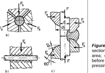
Figure 3. Fig.2. Clamping device: a) cross-section; b) longitudinal section of the clamping area; c) longitudinal section of the joint area, before (left) and after (right) applying the pressing force, ‘F’; Fs- squeezing force
Figure 3a presents a cross-section through the clamping die. It can be noticed that this is made of three distinct pieces, machined inside for allowing contact with the bar exterior surface. The space between these pieces makes possible the initial clamping of the bar. During up-setting, some of the bar material fills this space, creating longitudinal burrs. The cogged active surface of the clamps (Figure 3b) prevents the bar sliding in the clamps during
up-setting. The clamping length used during the experiments was LB = 40 mm (an empirical
technological prescription indicates as minimum value LB = 4 ⋅ d, where ‘d’ is the bar initial
diameter [1,2]).
The geometry of the clamp active side (d1 =1.4 ⋅ d,α = 50, β = 600) was designed to ensure
appropriate material flow and joint strength. Figure 3c presents the initial position of the clamps during up-setting, and final one, respectively.
The bars contact surfaces preparation, their smoothness, alignment and perpendicularity are
necessary for preventing their eventual relative sliding and compressive buckling. Furthermore, the cleaning and degreasing of the bars extremities were necessary before welding. The cleaning of the bars extremities with a rotating wire brush followed the mechanical cutting of the bars samples.
The initial standoff represents the initial length of the non-clamped end of the bar to be
welded. An optimum positioning of the samples in the clamps is described by an initial standoff capable to ensure accurate up-setting that produces welded joint of good quality.
The bars standoff is experimentally determined according to the base materials qualities.The
aluminium bars. An excessive standoff doesn’t lead to a correct pressing, causing the bars buckling occurs.
The up-setting force, ‘F’, is the actuation force produced by the hydraulic motor of the
toggle-lever press (F = 63,000 N). All the others technological parameters of butt cold welding
process of aluminium bars were determined at this up-setting (pressing) force value.
A special design clamping device ensured the bars self-blocking for low values of
clamping/squeezing force (Fs = 8,650 N), before upsetting. During upsetting, the bars
material actuates towards the clamping dies, developing forces of similar magnitude as the upsetting force. Thus, reaction forces of important values are generated in the clamping device, without increasing the squeezing force. In conclusion, whilst the necessary
squeezing force is about 7.30 times smaller than the upsetting one, the reaction forces have
the same order of magnitude as the pressing force. Consequently, the actuation of the
squeezing devices must be designed to provide the ‘Fs’ value, whilst the clamping device
itself should be able to carry out the bigger loads generated by the reaction forces.
The bar deformation, ‘δ’, is the ratio between the one-bar standoff variation (during
up-setting) and its initial standoff. Previous research [1] consider that cold pressure welding
process by single up-setting can be obtained only if a minimum deformation (
δ
min=
0
,
7
foraluminium) is exceeded during pressing.
The adequate selection of the welding equipment depends mainly on the necessary
up-setting force value, capable to ensure the achievement of cold welded joint.
2. 2. Butt Cold Welding material flow
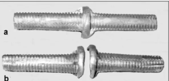
Different tests on butt pressing of aluminium bars of 10mm diameter were performed. The up-setting process was stopped at different values of bars deformation, for better understanding the material deformation process and the cold welded joint formation.
Experiments have confirmed that bars cold welding occurs at the deformation δ = 0.75.
Continuous pressing at higher deformation values led to corresponding decrease of standoff,
with an increased certitude of obtaining good quality joint.
Figure 4. Cold weld in case of δ = 0.68
The study intended also to determine the deformation critical value when the joint tensile
strength surpasses the base material ultimate strength. Thus, in case of δ = 0.68, the
formation of cold welding was noticed, but the joint had a poor strength due to the small area of the weld (Figure 4). At tensile tests, the samples failure occurred, without elongation, due to material loos of elasticity (cold hardening caused by pressing), in the weld area. Moreover,
a weld critical area was defined as the weld area when the joint strength is equal with the
base metal strength. Once surpassed the weld critical area, the joint failure initiates in base
metal.
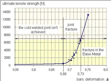
Figure 5 presents the experimentally determined diagram of ultimate strength of butt cold
welded aluminium bars as a function of deformation. Three domains corresponding to
different deformation ranges provide information on the progress of cold welding process. It
can be noticed that butt cold welding cannot be achieved at deformations inferior to δmin =
correspondent stress is equal with the value of the ultimate strength of base metal, for the
deformation δ = 0.73. Good quality joints are possible for bigger deformations, with respect to
other technological parameters, such as the preparation of the contact surfaces or the standoff value.
Figure 5. Ultimate strength of butt cold welded aluminium bars vs. bar deformation
Figure 6 shows the macro and microscopic images corresponding to the cold weld formation; the material flowing lines are visible on the joint macrostructure.
a) b)
Figure 6.Macro and microscopic images of CW joint (99.5%Al), (δ= 0.75); a) CW joint macrostructure; b) CW joint microstructure
Macro and microscopic images featured the aluminium behaviour during CW, showing:
- The increase of the material flow in the up-setting force direction, on the longitudinal axis of
the bars, in accordance with the deformation value. The grains are compressed on the direction of the predominant stress developed in the longitudinal axis of the bar, a typical
forging structure being thus obtained. The initial grains form (typical for the drawing
manufacturing process) modifies by pressing. The increased values of the normal stresses
couple at high deformation values lead to grains refinement and furthermore, to their reorientation on radial direction.
- The material flowing outside the clamps andweld seam and burr formation, ar presented in
Figure 6a. Due to internal stress values, grains slide mainly in the radial direction. At higher deformation values, as the microscopic images present, the flow lines orientations on radial
direction are observed. Initiation of the typical forging subgrain structures (Figure 6b), with
dimensions lower than 0.3 μm, allows for the fusion of the two lattices [5,6], thus achieving
the cold welding.
At microscopic level, the butt cold pressure welding process of the aluminium bars is produced due to the up-setting force when, in the contact area, the value of the normal stresses couple allows the initiation of the subgrain structures, with dimensions less than 0.3
3. FSW/FSP processes
3.1. FSW/FSP material flow and temperature
Nowadays, new techniques as solid-state Friction Stir Welding – FSW are currently used for obtaining different aluminium alloys qualitative joints. Although the welding may produce high tensile stresses (up to the yield stress) balanced by lower compressive residual stresses elsewhere in the component, FSW results in a much lower distortion and residual stresses owing to the low heat input characteristic of the process [10-12].
Recently, a derivative from FSW, Friction Stir Processing – FSP namely, was proved as being useful for inducing directed, localized, and controlled materials properties in any arbitrary location of components [11-12].
Basically, the FSP/FSW process has three stages: the penetration of the tool, when the local plasticity properties of the material quickly changes with temperature and the tool travel speed is characterised by acceleration from zero to the working value (Figure 2b-a,b,c); the working stage, when the travel speed and the pressing force are constant, as well as the rotating speed and the tool angles (Figure 2b-d); the tool retracting phase, when the travel speed is decreased by zero value and the tool is removed from the workpiece.
FSP/FSW process is characterised by some main technological parameters, namely: tool geometry, tool tilt and concordation angles (angles of the tool axis with the vertical direction in the longitudinal and transverse plane, respectively), rotating and travel speeds, plunging/working force.
The material flow during FSP/FSW is quite a complex deformation process of practical importance for tools design and materials microstructure transformations. Therefore, an overall pattern of the material flow hasn’t been reported yet. As example, the paper approaches the processing of as-cast AA 6061. The processed layer macrostructure is presented in Figure 7.
Figure 7. FSP macrostructures of AA6061 as cast aluminium alloy; 1-6 microstructures positions.
The base metal (BM) microstructure of as-cast AA 6061 consists of Al solid solution dendrites along with coarse silicon and intermetallic phases. Shrinkage porosity is also prevalent. FSW/FSP closed the shrinkage porosity and homogenized the as-cast microstructures by breaking up and evenly dispersing initial phases. Moreover, the resulting microstructures do not have a uniform grain size distribution for any one set of process parameters. Grain size varies from the top to the bottom as well as from the advancing to the retreating side. The differences in grain size likely are associated with differences in both peak temperature and time of application of temperature.
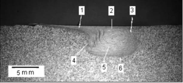
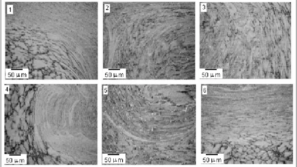
Figure 8 shows the typical features of all different zones in a single processed layer cross-section of as cast AA 6061 under processing condition of 1,120 rpm for the rotational speed and 320 mm/min for the welding speed. The positions 1-6 from Figure 8 are located in different microstructural zones. The micrographs show that the microstructure of the processed layer is complex and highly dependent on the position within the processed zone. This result arises because of the large local variations in the plastic flow and from the thermal history resulted from the material interaction with the tool.
attributed to an abrupt variation in the grain size and precipitate density [13]. The nugget zone grains suggest effective strains together with a microstructural evolution that occurs by a combination of hot working and a dynamic recovery or recrystallization. The temperature
reached in the nugget zone is known as being situated in the range of 450-500 0C for the
6061- Al alloy [14]. Distinct precipitates and coarsened grains are observed at the deformed regions of TMAZ. HAZ grains are severely coarsened by FSP (Figure 8, positions 1, 4).
Figure 8. Typical features of all different zones in a friction stir processed single layer cross-section of as cast AA6061: 1- flow patterns in the appendage zone; 2 – nugget zone; 3 – the retreating side of TMAZ; 4 – the advancing side of TMAZ; 5 – nugget bottom side; 6 – processed layer bottom side; (200x).
The characteristic annular-banded structure is distinctly observed to be asymmetric and more obvious on the advancing side (A) of processed zone as shown in Figure 8, positions 1, 2, 4. A severe deformation has also occurred along the top surface of the processed layer where the shoulder of the tool is in contact with the material. The flow lines from Figure 8 - positions 4, 2, 5 seem to represent plastic deformation increments that develop as the rotating tool moves through the processing line. Although, it is well known that the material is transported from A to the retreating side (R), Colligan [15] showed that with a threaded pin tool, the material from the upper part of the processed zone is pressed down, whereas the material from the lower part processed zone is moved toward the top surface. The material may travel many cycles around the tool before being redeposited. A little flow of material was observed near the bottom of the processed zone.
The effect of processing parameters on temperature was investigated by Arbegast and Hartley [11]. They reported that for a given tool geometry and depth of penetration, the maximum temperature depends on the rotation rate, while the rate of heating depends on the traverse speed. A higher temperature on the advancing side was noticed.
From different experimental investigations and process modeling, several conclusions can be underlined about the FSP/FSW thermal profile:
- the maximum temperature developed within the stir zone is below the melting point of the
materials;
- tool shoulder dominates the heat generation during FSP;
- the maximum temperature increases with increasing tool rotation rate at a constant tool
- the maximum temperature occurs at the top surface of the stir zone.
3.2. FSW/FSP parameters and their influence on processed material
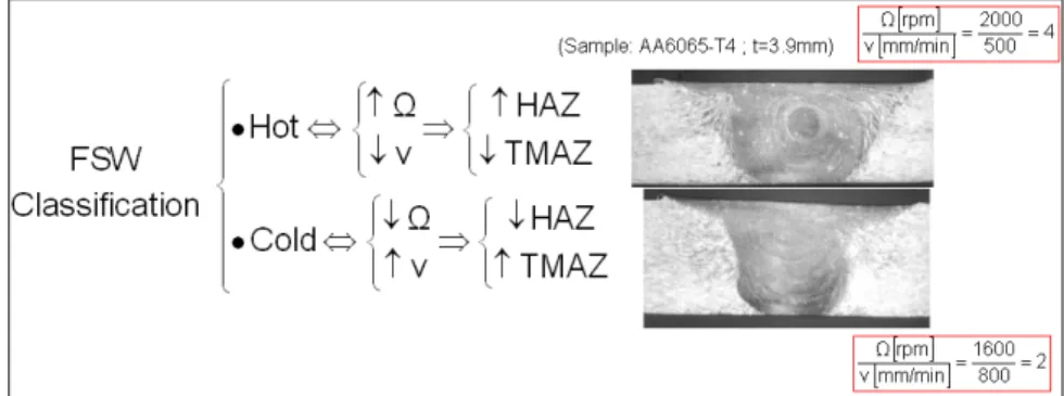
The main result of the research regards the influence of the friction stir main parameters (the tool rotational and advancing speed) on the material flow pattern around the tool (Figure 9) [12-13]. In the case of hot conditions, the visco-plastic material flow is more concentrated around the pin and the heat affected zone is wider resulting in a basin shape nugget. In the opposite, under cold conditions, the thermo-mechanically heat affected zone is wider and the heat affected zone is smaller.
Figure 9. FSW/FSP typical material flow patterns.
a)
Figure 10. FSW/FSP typical hardness profile: a) non heat treatable aluminium alloys (AA5083-H111; thickness: 4mm); b) heat treatable aluminium alloys (AA6061-T4; thickness: 4.8mm).
b)
The typical hardness fields obtained for the two main different groups of wrought aluminium alloys [13] are presented in Figure 10 a,b.
Figure 10b present the hardness profile results in case of processing a heat treatable aluminium alloy. Information about the typical location of the global minimum value of the harness field can be found here, located in the interface between the heat affected zone and the thermo-mechanically heat affected zone. Along the heat affected zone there is, typically, a local minimum hardness value due to processed material over-ageing.
The processed materials hardness profile enables a reliable assessment of its static mechanical resistance.
4. Conclusions
The main conclusions emerged after experiments related to butt cold welding of aluminium bars are:
- Small clamping force is needed at process beginning, ensuring only the initial bar
self-blocking in clamping dies. The actuation of the squeezing devices must be designed to
provide this smallvalue force, whilst the clamping device itself should be able to carry
out bigger loads generated by the pressed material reaction forces.
- Material flow due up-setting reflects its simultaneous displacement outside and inside
the clamps;
- The structural refinement microscopically observed has only mechanical origin.
- At microscopic level, the butt cold pressure welding process of the aluminium bars is
produced due to the up-setting force when, in the contact area, the value of the normal stresses couple allows the initiation of the subgrain structures, with dimensions less
than 0.3 μm, capable to fusion and create a common lattice.
Moreover, after FSW/FSP processing of aluminium alloys it can be conclude that:
- The material flow is a complex deformation process of practical importance for tools design and materials microstructure transformations; an overall pattern of the material flow hasn’t been reported yet.
- The material temperature increase within and around the stirred zone; Its distribution directly influences the microstructure of the processed materials, such as solid state transformations, grain size, coarsening and dissolution of precipitates, and resultant mechanical properties of the processed surface.
- Tool geometry is an important factor for producing required materials microstructures,
but at the present, tool design information is very limited, protected by patents.
- The processing parameters, including the tool rotation rate, the traverse speed, the spindle tilt angle, and the target depth, are crucial to produce the bulk material modifications.
- The experiments regarding the influence of the processes main parameters (the tool rotational and advancing speed) on material flow pattern around the tool in visco-plastic conditions indicate a larger heat affected zone than under cold conditions.
- The processed materials hardness profile enables a reliable assessment of its static mechanical resistance
These results are important milestones and constrains for the solid state processes simulation using finite element method modelling.
References
[1] Georgescu, V., Iordachescu, M., Georgescu, B., Practica sudării prin presiune la rece
(Cold pressure welding practice), E.T. Publishing House, Bucuresti, 2001.
[2] Iordachescu, M., Contributii la sudarea prin presiune la rece cap la cap (Contributions
2005.
[3] Zhang W., Bay N., Cold welding - Experimental investigation of the surface preparation
methods, Welding Journal 76 (8): S326-S330 AUG 1997
[4] Zhang W., Bay N., Cold welding - Fractographic investigation of the weld formation,
Welding Journal 76 (9): S361-S366 SEP 1997
[5] Zhang W., Bay N., Cold welding - Theoretical modeling of the weld formation, Welding
Journal 76 (10): S417-S420 OCT 1997
[6] Bay N., Mechanisms producing metallic bonds in cold welding, Welding Journal 62 (5):
S137-S142 1983
[7] Bay N., Cold forming of aluminium - State of the art, Journal Of Materials Processing
Technology 71 (1): 76-90 NOV 1 1997
[8] Constantin, E., Iordachescu, M., Scutelnicu, E., New approaches on Aluminium butt
joints design evaluation using FEA simulation, ASR International Conference:
Achievements and perspectives in producing welded construction for urban environments, Editura SUDURA, 11 July 2003, Bucharest, Romania, pp. 311-321.
[9] Nicholas, E.D., Friction Processing Technologies, Welding in the World, Vol. 47, n°
11/12, 2003.
[10] Thomas, W.M., Staines, D.G., Norris, I.M., Frias, R., Friction Stir Welding – Tools and
Developments, Doc IIW-1639-03.
[11] Mishra, R.S., Ma Z.Y. Friction stir welding and processing, Materials Science and
Engineering R 50 (2005) 1–78, Elsevier, 2005.
[12] Iordachescu, M., Iordachescu, D., Scutelnicu, E., Vilaca, P., Ocana, J. L., Aluminium
friction stir processing – roughness vs. macro/microscopically results, Welding in the
World, Vol. 51, Sp. Iss., 441-448, 2007.
[13] Vilaça, P., Santos, J. P., Góis, A., Quintino, L., Joining Aluminium Alloys Dissimilar in
Thickness by Friction Stir Welding and Fusion Processes, Welding in the World, Vol.
49, No. 3/4, 56-62, 2005.
[14] Staron, P., Kocak, M., Williams, S., Wescott, A., Residual stress in friction stir-welded
Al sheets, Physica B 350, e491–e493, Elsevier, 2004.
[15] Colligan, K., Material Flow behaviour during Friction Stir Welding of Aluminium,