Integrated thermal and lighting analysis of spaces with controled complex fenestration systems and artificial lighting during the design stage
145
0
0
Texto completo
(2)
(3) To my family and friends… in Chile, Canada and anywhere else.. ii.
(4) AKNOWLEDGMENTS This work was supported by the National Commission for Science and Technology (CONICYT) under the research grants FONDECYT 1111001 and CONICYT/FONDAP 15110020. This work was partially developed during my stay at Concordia University (Montreal, Canada) supported by the Canadian Government via the Canada-Chile Leadership Exchange Scholarship. Apart from the supporting entities, I would like to thank my advisors Dr. Sergio Vera and Dr. Waldo Bustamante, who helped and guided me all this time, and gave me very important opportunities such as researching abroad and presenting on international workshops. I would also like to thank Dr. Paul Fazio, Dr. Jiwu Rao, Dr. Hua Ge, Costa Kapsis, and the students from Concordia University. Without their help and hospitality, this work and my internship in Canada would have been much harder. Finally, I would like to dedicate some lines to thank a great number of people who, although not having anything to do with my research, helped me during my whole MSc. Starting from Dr. Alejandro Echeverria, from Pontificia Universidad Católica de Chile, Greg Ward, from Dolby Laboratories Inc., Dragan Curcija, Simon Vidanovic, Andy McNeil, Eleanor Lee and Stephen Selkowitz from the Lawrence Berkeley National Laboratories (LBNL), Rob Guglielmetti, from the National Renewable Energy Laboratories (NREL), Marilyne Andersen, from École Polytechnique Fédérale de Lausanne (EPFL) and Costa Kapsis, from Concordia University. Also, I would like to thank the whole Radiance mailing list, which is an excellent community that is always willing to help.. iii.
(5) TABLE OF CONTENTS Pag. DEDICATORY ........................................................................................................... ii AKNOWLEDGMENTS .............................................................................................. ii LIST OF TABLES .................................................................................................... viii LIST OF FIGURES .....................................................................................................ix RESUMEN ................................................................................................................ xii ABSTRACT ............................................................................................................. xiii 1. . INTRODUCTION ............................................................................................... 1 1.1 Background information ............................................................................ 1 1.1.1 Thermal simulation software ....................................................... 5 1.1.2 Lighting simulation software ....................................................... 7 1.1.3 Integrated lighting/thermal analysis ............................................ 9 1.1.4 Characterization of Complex Fenestration Systems .................. 10 1.2 Research opportunities ............................................................................. 12 1.3 Objectives ................................................................................................ 13 1.4 Hypothesis ............................................................................................... 14 1.5 Methodology ............................................................................................ 14 1.6 Thesis structure ........................................................................................ 15 1.7 Results ...................................................................................................... 15 1.8 Conclusions .............................................................................................. 17 .
(6) 1.9 Perspective and future work .................................................................... 18 2. . LITERATURE REVIEW .................................................................................. 21 2.1 Abstract .................................................................................................... 21 2.2 Introduction .............................................................................................. 21 2.3 Thermal Simulations ................................................................................. 24 2.3.1 Thermal simulation methods for CFS........................................ 25 2.3.2 Thermal Simulation tools .......................................................... 26 2.4 Lighting simulations ................................................................................. 27 2.4.1 Static simulation methods .......................................................... 28 2.4.2 Dynamic simulation methods .................................................... 30 2.4.3 Daylighting simulation software................................................ 34 2.5 Integrated lighting and thermal simulation ............................................... 36 2.5.1 Integrated lighting and thermal simulation methods ................. 37 2.5.2 Integrated lighting and thermal simulation software ................. 38 2.7 Assessment of the Bidirectional properties of Complex Fenestration Systems .................................................................................................... 40 2.7.1 Laboratory measurements .......................................................... 40 2.7.2 Ray-tracing techniques .............................................................. 41 2.7.3 Mathematical assembly of multilayer fenestration systems: The LBNL method ............................................................................ 42 2.8 Discussion ................................................................................................. 43 2.9 Conclusions ............................................................................................... 44 .
(7) 3. . EVALUATION OF RADIANCE’S GENBSDF CAPABILITY TO ASSESS BIDIRECTIONAL SOLAR PROPERTIES OF COMPLEX FENESTRATION SYSTEMS ......................................................................................................... 46 3.1 Abstract ..................................................................................................... 46 3.2 Introduction ............................................................................................... 46 3.3 Bidirectional and directional properties of CFS ....................................... 51 3.4 Methodology ............................................................................................. 54 3.5 Results and analysis .................................................................................. 56 3.6 Discussion ................................................................................................. 61 3.7 Conclusions ............................................................................................... 64 . 4. . A SIMPLE METHODOLOGY FOR INTEGRATING LIGHTING AND THERMAL SIMULATION OF SPACES WITH CONTROLLED LIGHTING AND COMPLEX FENESTRATION SYSTEMS ............................................ 66 4.1 Abstract ..................................................................................................... 66 4.2 Introduction ............................................................................................... 66 4.3 Related work ............................................................................................. 68 4.4 Methodology ............................................................................................. 70 4.5 Introduction of a new program: mkSchedule ........................................... 73 4.6 Case study ................................................................................................. 75 4.7 Conclusions ............................................................................................... 79 .
(8) 5. . A WORKFLOW FOR PERFORMING INTEGRATED THERMAL AND LIGHTING ANALYSIS OF SPACES WITH CONTROLLED COMPLEX SHADING SYSTEMS AND ARTIFICIAL LIGHTING DURING THE DESIGN STAGE .............................................................................................. 81 5.1 Abstract ..................................................................................................... 81 5.2 Introduction ............................................................................................... 81 5.3 Building, surroundings and window openings design .............................. 85 5.4 Fenestration system design ....................................................................... 86 5.5 Fenestration system properties assessment ............................................... 87 5.6 Schedule creation ...................................................................................... 88 5.6.1. Description of a new program ................................................... 89 . 5.6.2 Generating the schedule ............................................................. 90 5.7 Lighting simulation ................................................................................... 93 5.8 Energy performance simulation ................................................................ 95 5.9 Conclusions and future work .................................................................... 97 BIBLIOGRAPHY ...................................................................................................... 98 .
(9) LIST OF TABLES Pag. Table 1: Solar properties of the slats to be tested .......................................................... 56 Table 2: Root Mean Square and Maximum Difference between the two methods, for all 16 cases ........................................................................................................... 57 Table 3: Algorithms used for controlling Luminaires and Venetian blinds .................. 77. viii.
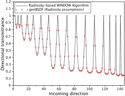
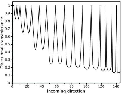
(10) LIST OF FIGURES Pag. Figure 1:. Solar, luminous efficacy of the eye and blackbody emission spectrums (Karlsson, 2001).............................................................................................. 2 . Figure 2:. Example of perforated shading device, allowing the close observer to see through while still having an important percentage of opacity....................... 4 . Figure 3:. Example of the subdivision of the incoming and outgoing semi-hemispheres ...................................................................................................................... 24 . Figure 4:. Three Phase Method diagram ....................................................................... 32 . Figure 5:. a) Shading system – Overhang and vertical fin. b) Complex fenestration system – exterior venetian blind ................................................................... 48 . Figure 6:. Subdivision of the incoming and outgoing semi-hemispheres ..................... 50 . Figure 7:. Render of case C45 of the venetian blind. .................................................... 55 . Figure 8:. Directional transmission, genBSDF, vs. Radiosity for all 16 cases. ............. 58 . Figure 9:. Bidirectional transmission, genBSDF, vs. Radiosity for all 16 cases. .......... 58 . Figure 10: Difference between the Radiosity-based WINDOW algorithm and the results of genBSDF, for all elements of the bidirectional transmission matrix of the 16 cases. ........................................................................................................ 59 Figure 11: Difference between the Radiosity-based WINDOW algorithm and the results of genBSDF, for all elements of the directional transmission vector of the 16 cases. ............................................................................................................. 59 Figure 12: Directional transmittance of case C45, comparison between genBSDF and Radiosity based on WINDOW algorithm. .................................................... 60 Figure 13: Directional transmittance of the case A0, comparison between genBSDF and Radiosity based WINDOW algorithm. ......................................................... 60 Figure 14: Renders of a) Venetian blind with Lambertian materials. b) The same Venetian blind, but with 90% specular materials. c) Set of horizontal louvers made of 90% specular material and 4 mm thick louvers .............................. 62 ix.
(11) Figure 15: Directional transmittance of a venetian blind positioned in 0, made of a material with 0% specularity (Lambertian) and 70% solar reflectance. ....... 62 Figure 16: Directional transmittance of a venetian blind positioned in 0, made of a material with 90% specularity and 70% solar reflectance ............................ 63 Figure 17: Directional transmittance of a venetian blind positioned in 0, made of a material with 90% specularity, 70% solar reflectance and 4 mm thick louvers ...................................................................................................................... 63 Figure 18: Methodology used in (Wienold et al., 2011) for coupled lighting and thermal analysis.......................................................................................................... 71 Figure 19: Proposed methodology for performing integrated thermal and lighting analysis.......................................................................................................... 72 Figure 20: mkSchedule flow chart. Everything inside the gray square is repeated on each time-step ............................................................................................... 74 Figure 21: Space used for case study ............................................................................. 76 Figure 22: Lighting power using dimmed and on/off control strategies, for the days 1 to 2 of the year .................................................................................................. 78 Figure 23: Venetian blind position during the first 2 days of simulation. 1 corresponds to 30° and 2 to 45° ........................................................................................ 78 Figure 24: Illuminance level in the floor at 9 am of January 1st for both cases. ........... 79 Figure 25: Holistic analysis and design workflow ......................................................... 83 Figure 26: Space to be simulated. Different window groups are shown in different colors ............................................................................................................. 84 Figure 27: Space to be simulated and surroundings imported from Google Earth. ....... 85 Figure 28: East-shading system designed in SketchUp.................................................. 86 Figure 29:. Image rendered in Radiance using tensor-tree BSDFs and proxy geometry .................................................................................................................... 87 . Figure 30: Space showing two luminaire sets ................................................................ 90 Figure 31: Position of the venetian blind according to the irradiance in the south facade for each algorithm. ........................................................................................ 91 x.
(12) Figure 32: South-facing venetian blind position during the first two days of the year for both algorithms ............................................................................................. 92 Figure 33: Illuminance in sensor 1 for both algorithms, during the first two days of simulation...................................................................................................... 93 Figure 34: Space simulated with the analysed workplane in red. .................................. 94 Figure 35: Results of the lighting simulation in Lightsolve format. .............................. 94 Figure 36: Transmitted solar energy through the South-facing window, reported from EnergyPlus. ................................................................................................... 95 Figure 37: Difference in energy consumption of the space with the 100W/m2 and the 700 W/m2 algorithm...................................................................................... 96 . xi.
(13) RESUMEN Estudios prueban que los sistemas de protección solar son beneficiosos tanto para las condiciones de confort como para el desempeño energético del edificio. Sin embargo, dichos dispositivos se consideran Sistemas Complejos de Fenestración (SCF), los cuales presentan características ópticas muy difíciles de modelar en software de simulación tanto lumínica como térmica. Utilizando una propiedad llamada Función Bidireccional de Distribución de Dispersión (BSDF, por sus siglas en inglés), herramientas de simulación han sido provistos de módulos que les permiten modelar dichos sistemas más correctamente, considerando las complejidades ópticas de los mismos. Debido que los SCF se instalan para proveer un ambiente confortable tanto en lo visual como en lo térmico, realizar simulaciones integrales de ambos dominios resulta fundamental. Además, debido a que los ocupantes y/o sistemas automáticos manejarán cortinas y persianas y controlarán las luminarias, se deduce que la simulación no sólo debe ser integral, sino que además debe incluir control. El propósito de esta tesis es dar los primeros pasos hacia una herramienta que permita realizar dichos análisis para espacios con iluminación artificial y SCF controlados. Así, durante el proceso de revisión bibliográfica se concluyó que la obtención de BSDF solares de los sistemas a evaluar, y la realización de una simulación integrada de los dominios térmico y lumínico eran fundamentales para realizar análisis holísticos y requerían simplificación. Este trabajo muestra, comparado resultados con soluciones analíticas, que la herramienta genBSDF es capaz de evaluar las BSDF solares de SCFs. Además, explica el desarrollo de un nuevo programa, mkSchedule, que facilita la integración de software térmicos y lumínicos, y propone una metodología que permite evaluar integralmente un edificio durante el proceso de diseño, permitiendo modificar el edificio mismo, los SCFs, luminarias y algoritmos de control. Tanto mkSchedule como la nueva metodología son probados con un estudio de caso simple.. xii.
(14) ABSTRACT Studies show that shading devices have a positive impact on the energy performance of buildings and in the visual and thermal comfort of their interior spaces. However, such systems are classified as Complex Fenestration Systems (CFS), which usually present very complex optical properties, making them very hart to model within energy performance and lighting simulations. In the last few years, using the concept of Bidirectional Scattering Distribution Function (BSDF), different software have been provided with modules that allow modeling them more accurately, taking into account their complex optical behavior. Since CFS are installed for providing simultaneous enhanced lighting and thermal environments, performing integrated simulations between those two domains is a necessity. Also, since shades and luminaires of the building will be handled by occupants and/or automatic systems, simulation not only has to be integrated, but also has to involve control. The purpose of this thesis is to advance in the development of a tool that allows performing integrated lighting/thermal analysis of spaces with controlled CFS and artificial lighting. According to this, it was concluded from the literature review that the assessment of the solar BSDFs of CFS, and the implementation of a methodology for performing integrated analysis are crucial steps in the process, and required simplification. This thesis shows, comparing results with analytical solutions, that genBSDF tool is capable of assessing solar BSDFs of CFS. Also, the development of a new program, mkSchedule, is explained. This program intends to simplify and improve the integration of lighting and thermal software. Finally, a design methodology is proposed. This methodology allows performing integrated lighting and thermal analysis of spaces with controlled artificial lighting and CFS. Even more, it allows designing not only the building itself, but also the CFS, the artificial lighting and the control algorithms. The thesis is closed with an analysis of a simple case study.. xiii.
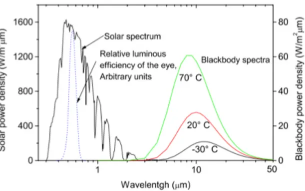
(15) 1. 1.. INTRODUCTION. 1.1. Background information. The purpose of a building is to provide a healthy, comfortable, safe and productive environment where the occupants can live and/or work. Nowadays, mechanical and electrical systems are capable of forcing an interior environment to be comfortable and healthy by ventilating, controlling the indoor temperature and relative humidity and providing artificial lighting when needed. However, these practices have led the building sector to account for approximately 20% of the total energy consumption of the world (EIA 2013), 40% in developed countries like UK and US (DECC 2013; US. DOE 2013), and 28.8% in the case of Chile (MinEnergia 2012). This situation is unaffordable to a world that is affected by global warming, and whose urban population is growing (The World Bank, 2013). Also, the results of using electrical systems for forcing a space to be comfortable are not always the best. For example, studies show that daylight has a statistically significant and positive impact on human behavior (Heschong, Wright, & Okura, 2002), an effect that can be only caused by the sun. Solar radiation is, by far, the most important energy source of the planet. Approximately half of it is visible to human eye (Duffie & Beckman, 1996), and can be called daylight (Figure 1), but its entireness will spontaneously be transformed into heat when it ends absorbed by the massive objects in the environment. According to that, it may be concluded that the sun provides free and renewable light and heat, which may be used to passively maintain a good thermal and visual environment in a building. In order to harvest solar radiation, the building´s façade must have transparent sections, which are referred as fenestration. Even though many of the techniques and methodologies presented on this document can be extrapolated to other types of fenestration elements, that term will usually be thought as windows or skylights on this thesis. A fenestration system, on its part, consists on the whole fenestration assembly..
(16) 2. For example, in the case of windows, it would consider the glazing, the frame and its components, and any shading or light-redirecting device attached to it.. Figure 1: Solar, luminous efficacy of the eye and blackbody emission spectrums (Karlsson, 2001). Fenestration systems are elements of the building’s envelope that must be carefully designed and dimensioned. If they are excessively big, lack of privacy, visual discomfort (glare), lack of thermal insulation and excessive solar heat gains may be induced. On the contrary, it they are excessively small, lack of daylight, views to exterior and solar heat gain problems may exist. According to this, fenestration is probably one of the most important façade elements to consider during a building’s design, and it have to be taken into account from the early stages of the process. There are, however, elements that permit having the benefits of both big and small fenestration surfaces simultaneously. For example, multiple glazing assemblies, low emissivity coatings and other products have reduced the U-value of the fenestration systems available, allowing installing larger fenestration surfaces without affecting the thermal insulation of the whole building envelope. Another example is the use of.
(17) 3. perforated shading devices, which allow viewing to the exterior (i.e. viewing through when the observer is close, Figure 2), but not to the interior (i.e. when the observer is far away). This kind of shading device blocks solar radiation without affecting panoramic views and privacy. Even more, it has been shown that the use of shading systems have a positive impact in the energy performance of the building (Florides et al. 2000; Tzempelikos and Athienitis 2007) and in its indoor environment quality (Tzempelikos et al. 2010). As expected, many of these films and shading devices have transformed the fenestration systems from being just a glazing assembly fixed to a frame to be complex construction elements. Thus, a new concept arises: Complex Fenestration Systems (CFS). Complex Fenestration Systems (CFS) have been defined as those that include a nonspecular layer within the glazing assembly (Laouadi & Parekh, 2007). This definition includes fenestrations attachments that have complex thermal and optical behaviour (ASHRAE, 2013) such as all non-specularly transmitting fenestration system components like fabric shades and louvered blinds (McNeil, Jonsson, Appelfeld, Ward, & Lee, 2013). These systems present complex and strong angular dependency on their optical properties. According to that, they are very difficult to model within energyperformance and daylighting simulations, making it hard to predict their impact on the energy consumption, indoor lighting conditions and thermal and visual comfort. This difficulty ultimately forces the HVAC and lighting designers to oversize equipment in order to assure comfort. The strong angular dependency of CFS´s optical properties also make it impossible to classify them using standard performance indexes For example, the Shading Coefficient and the normal Solar Heat Gain Coefficient are no longer representative values of the CFS´s performance. On the contrary, every property will have to be expressed as a function of the incoming and outgoing angle. Currently, CFS are usually optically characterized using the so-called Bidirectional Scattering Distribution Function (BSDF) (Nicodemus, 1970; Nicodemus, Richmond, & Hsia, 1977). The concept of BSDF.
(18) 4. corresponds to a four-dimensional function that is defined as the ratio of incoming irradiance over outgoing radiance. In consequence, this concept is capable of fully represent the radiant behavior of objects, making it highly useful for the field of CFS.. Figure 2: Example of perforated shading device, allowing the close observer to see through while still having an important percentage of opacity. When used for modeling CFS, the BSDFs are usually presented in the form of matrices instead of analytical functions. These matrices are the most important optical properties of CFS, and are used for solar heat gain (Klems, Warner, & Kelley, 1995a; Klems, 1994a, 1994b) and daylighting (Saxena, Ward, & Perry, 2010) calculations. On these matrices, each column represents an incoming three-dimensional direction, and each row represents an outgoing three-dimensional direction. Thus, the item in the ith row and jth column of the matrix represents the fraction of the radiation that came from the jth direction and left by the ith direction. Since CFS are usually installed to provide enhanced thermal and lighting environments while taking care of heating and cooling energy demand, the evaluation of their impacts has to be carried out holistically. However, this is not an easy task because the methodologies developed for performing thermal simulations are very different to those used for daylighting simulations. That is probably the reason why calculation software have specialized on one of those domains, and the integrated analysis often have to be made by artificially coupling two single-domain software or by avoiding the use of any existent tool..
(19) 5. The next sections analyze the main single-domain lighting and thermal software, as well as the methodologies used for coupling them. 1.1. 1Thermal simulation software These software were originally designed for carrying out whole energy performance building simulations, including lighting. Because of that, they are provided with natural and artificial lighting calculation modules, but they are very simplified methodologies that are no longer used by the lighting-dedicated software due to accuracy reasons. This analysis covers only two of the most commonly used energy-performance simulation tools, focusing on their capabilities of simulating building spaces with CFS. However, more detailed explanations of how both of them treat the Complex Fenestration Systems are given on Chapter 2. EnergyPlus Developed by the U.S. Department of Energy (DOE), this software is a combination of BLAST and DOE-2 (Crawley et al., 2001, 2004a), and it is considered a state-of-the-art energy-performance simulation tool. This software allows defining up to two illuminance sensors on each zone with the purpose of controlling the luminaires (dimmable, On/Off and some other simple options). Luminaire modeling allows as input only the power density in W/m2, and after the simulation it is not possible to see the illuminance on the workplanes. On the other hand, control is done based on the daylighting registered by the sensors, which is calculated using the Daylight Factors (LBNL, 2013a). Also, EnergyPlus assumes that the power density installed will provide, at night, exactly the desired illuminance (set-point) in the sensors, no matter what kind of luminaires are installed, or where they are located. It is worth mentioning that Tregenza (1980) experimentally proved the daylight factor to be a poor predictor of interior horizontal illuminance..
(20) 6. EnergyPlus has been able, since long ago, to model Complex Fenestration Systems such as curtains, blinds, louvers and rollers by considering them to be isotropic perfect diffusers (i.e. with no angular dependency in their optical properties) (Winkelmann, 2001). This corresponds, probably, to an assumption required to transform the CFS problem into something manageable. However, it is trivial to notice this gross assumption is obviously incorrect, and is bound to lead to incorrect results. Latest versions of EnergyPlus allow defining CFS using their BSDFs (LBNL, 2013a), properties that are used for calculating daylighting and solar heat gains. This permits modeling the CFS as black-boxes, without any geometry or material properties input into the software, as explained in (Kuhn, Herkel, Frontini, Strachan, & Kokogiannakis, 2011). Therefore, if the BSDFs of the CFS that is going to be evaluated are known, EnergyPlus will be able to handle it with complete generality. EnergyPlus is capable of modifying, on each time-step, the CFS definition, allowing simulating control. This is done using the Energy Management Simulation (EMS), that allows using simulation-generated data (i.e. internal drybulb temperature, HVAC energy consumption or surface temperature) or scheduled data. ESP-r This software is, arguably, a less user-friendly and more research-focused energy performance simulation tool than EnergyPlus. ESP-r is capable of using BSDFs (Frontini, Kuhn, Herkel, Strachan, & Kokogiannakis, 2009) for simulating built spaces with CFS, however, the treatment is different from EnergyPlus, as will be explained later, in Chapter 2. This software also allows controlling CFS using schedules and simulationgenerated data. ESP-r modules for handling CFS were found to be less documented than those of EnergyPlus, being this one of the reasons for focusing this research on the latter..
(21) 7. 1.1.2 Lighting simulation software There are two main algorithms for performing lighting calculations: ray-tracing and radiosity. The radiosity method has its origins on the radiation heat transfer problems, and its equation represents a fundamental energy balance (Greenberg, Cohen, & Torrance, 1986). This method assumes every object to have a lambertian (perfect diffuser) material, making it not recommended for modeling spaces with relatively specular elements (Tsangrassoulis & Bourdakis, 2003) such as a light-redirecting devices or a wide variety of CFS. Also, this algorithm requires subdividing the scene into small sub-surfaces and calculating view factors. This can take a long time when the geometry is complex or is composed by many surfaces. This method is used by tools such as AGi32 (AGi32, 2013) and Dialux (DIAL, 2013). Ray-tracing, on the other hand, can deal with complex geometries and nonlambertian materials. Also, this method does not require subdividing surfaces, and it permits inserting non-flat geometries such as spheres, cones and cylinders. The main drawback of the ray-tracing algorithm is that it requires intensive computational resources. This method is commonly used by photorealistic rendering software. Since ray-tracing requires a long time to carry out calculations, and radiosity is not suitable for some common situations, none of them is actually used for annual simulations. For this last purpose, methods such as the Daylight Coefficients (Tregenza & Waters, 1983) were developed. This method requires ray-tracing or radiosity algorithms to compute, just once, the Daylight Coefficients matrix, and then, the annual simulation is performed by just using simple matrix multiplication. This matrix can be reused as long as the geometry and materials of the model are kept constant, meaning that this method only permits easy and fast modification of the sky conditions. This means that the Daylight Coefficients method is very efficient for performing annual simulations of built spaces whose geometry (including the CFS) is kept constant..
(22) 8. Since the Daylight Coefficients method only allows modifying the sky, it is not suitable for the design process, where the building’s shape and materials are constantly changing. For this reason, a new method was derived from it: the Three-phase method (McNeil, 2013a; Saxena et al., 2010). This method, validated by McNeil & Lee (2013), divides the calculation process into three phases, allowing efficiently modifying not only of the sky but also of the fenestration systems, which are represented by their BSDFs. The Daylight Coefficient and the Three-phase methods as well as the concept of BSDF will be more deeply explained in Chapter 2. Radiance Radiance (Ward, 1994) is probably the best, most flexible and complete lighting software available (Ochoa, Aries, & Hensen, 2012), making that most of the other lighting software come from it (Galasiu & Reinhart, 2008). Radiance permits making natural and artificial lighting calculations. Also, it allows implementing the Daylight Coefficients method and the Three-phase method. The major drawback of Radiance is that it requires advanced knowledge and expertise. Radiance is a Unix-like set of programs, without any graphical interface, which confuses most of the new users. Also, making geometry directly on Radiance is a tedious task, and the use of some other graphical interface is recommended (i.e. Autodesk Ecotect ®, Trimble SketchUp ®). Daysim Daysim (Reinhart, 2013) is a Radiance-based software that uses the Daylight Coefficients method and the Perez et al. sky models (Perez, Ineichen, Seals, Michalsky, & Stewart, 1990; Perez, Seals, & Michalsky, 1993) for carrying out daylight calculations. One of its advantages is that this software includes an occupant behavioral model called Lightswitch 2002 (Reinhart, 2004), which models how occupants handle venetian blinds and artificial lighting in private offices of one or two people..
(23) 9. Daysim is widely used for daylighting and it has been validated even for calculations of offices with CFS (Reinhart & Walkenhorst, 2001). However, it has the disadvantages related to the Daylight Coefficients method. That is, modifying the building or CFS’ geometry will force to recomputed the DC matrix, a timeconsuming process. 1.1.3 Integrated lighting/thermal analysis Since CFS are often installed to provide simultaneous enhanced visual and thermal environments, performing holistic analysis is very important. It is worth mentioning that, since occupants might have a significant impact on the energyperformance of the building (Guerra Santin, Itard, & Visscher, 2009), implementation of models that account for their behavior is required. On this thesis, such model will be considered to be control algorithms. In fact, for the purpose of this thesis, control refers to algorithms that intend to emulate automatic systems, or human behavior, choosing the new building condition according to other measurable quantities. For example, modeling the occupants reaction to discomfort or other parameters, such as Lightswitch 2002 (Reinhart, 2004). According to that, the building’s analysis does not only have to be integrated, but also must allow implementing control. A very interesting work on this area was made by Milan Janak (1997) by coupling ESP-r and Radiance to a time-step level. That is, at each simulation time-step, the two programs performed calculations and interact with each other. This work seem to be promising, however, no posterior related work was found on the literature. A second approach was done by Athienitis and Tzempelikos (2007) for analyzing a perimeter office. With this approach, finite difference models were developed for studying the thermal domain. On the other hand, the lighting calculations were done by estimating the direct solar radiation over the space, and then spreading it using the radiosity method. A similar approach is used by iDbuild (Petersen & Svendsen, 2010), a Matlab® GUI that allows making informed decisions on early stages of design. This tool.
(24) 10. was verified to be accurate enough for early stages of design, but it is limited to one rectangular office with only one window and it should not be used for detailed simulations. By indirectly coupling Daysim with ESP-r, Wienold, Frontini, Herkel, & Mende (2011) carried out holistic analysis of spaces with controlled CFS and artificial lighting. The analysis was made in three stages: first, multiple Daysim simulations were made; secondly, a control algorithm was implemented over all the results, in order to choose the desired CFS position and artificial lighting power at each timestep; finally, this information was written in schedules, and transferred to ESP-r to control the CFS in and also to modify the internal gains generated by the artificial lighting, performing the thermal simulation. This methodology was implemented informally, and has a lot of potential to be enhanced. Also, the authors do not explain how they implemented the control strategies, so it is assumed that no specific or optimized approach was utilized. Although it is not a methodology, OpenStudio (Guglielmetti, Macumber, & Long, 2011) is an open source tool that intends to combine Radiance with EnergyPlus. Nowadays, it allows using the Three-phase method, the Daylight Coefficients method, calculating simplified glare (Wienold, 2009) and permits replacing the EnergyPlus lighting calculations by Radiance calculations. However, this replacement is not done on each time-step, so the information has to be passed using schedules. This schedules will only control the artificial lighting, and the definition of the different control strategies is time-consuming and complex. Implementation of CFS control has not been added to OpenStudio. 1.1.4 Characterization of Complex Fenestration Systems As is was explained in the previous sections, BSDFs can be used for making daylighting simulations within Radiance, and detailed thermal simulations in ESPr and EnergyPlus. However, obtaining these properties might not be a simple task. In fact, although these programs allow BSDF as inputs, the bidirectional properties.
(25) 11. of shading systems are rarely found. If the task is to design a new CFS, the problem will be practically impossible to solve. There are three main sources of BSDFs: Laboratory measurement, analytical models and ray-tracing simulations. From them, laboratory measurements are probably the most reliable source. However, they can take a long time, and they need very special equipment to (Andersen & de Boer, 2006). Also, some CFS with macroscopic discontinuities (i.e. Venetian blinds) cannot be measured because the size of the light sources of the measurement equipment is comparable to the size of the discontinuity (McNeil et al., 2013). On the other hand, analytical models, such as the one documented by Carli Inc. (2006a) usually rely on the Radiosity method, which involves assumptions that are often inappropriate for modeling CFS, such as assuming that all materials are lambertian (perfectly diffusive). These models, when they are developed, can carry out calculations in a short time; however, developing the model will be time consuming and require validation. Finally, ray-tracing simulations try to emulate the laboratory measurements in a virtual environment. Despite of having all the advantages of the ray-tracing algorithm, the material properties and the geometry are required as inputs. Thus, correctly modeling the geometry and materials of the CFS is a crucial task, since the resulting BSDF will be as good as the input model. The use of ray-tracing techniques for the assessment of the visible bidirectional properties of custom shaped systems of known materials can be made using commercial tools like the ray-tracer TracePro®, or using Radiance’s program genBSDF. TracePro® is a forward ray-tracer developed by Lambda Research Corporation, validated against laboratory measurements carried out by Andersen and Scartezzini (2003) and Andersen, Rubin, and Scartezzini (2003). On the other hand, genBSDF uses Radiance’s backward ray-tracing, and was specifically developed for calculating visible bidirectional properties of CFS. It was validated in (McNeil et al., 2013) and was then used in the process of validating the ThreePhase method (McNeil & Lee, 2013). TracePro® has also been successfully used.
(26) 12. for assessing solar bidirectional properties (Rubin, Jonsson, & Kohler, 2007). In contrast, genBSDF has not yet been formally documented as a tool that can be used for this purpose, although this application is mentioned in (McNeil et al., 2013). 1.2. Research opportunities. From the literature review, it was concluded that the process of performing integrated thermal and lighting analysis of built spaces with CFS during the design state is not far from being possible. However, the following research opportunities are considered to be important contributions to achieve it:. Evaluation of Radiance’s genBSDF as a tool for assessing solar BSDFs of CFS. Ray-tracing techniques were defined as the best option to assess the BSDF of CFS because of their robustness (they do not require so many assumptions and are not bound to specific geometries) and because the do not require manufacturing prototypes. According to that, since Radiance’s genBSDF is distributed free of charge, and it is available for everyone, it is considered an excellent choice for performing this task. However, this tool has only been validated for the visible range. In consequence, validating genBSDF as a tool for calculating solar BSDF would be an important step forward to perform more accurate energy-performance simulations during the design stage. Development of a simple methodology for integrating lighting and thermal simulations using Radiance and EnergyPlus All the methodologies found on the literature which are developed for this purpose present weaknesses and strengths, being a usual drawbacks the complexity of their implementation or the accuracy of their results. A simple methodology that allows integrating lighting and thermal simulations without sacrificing accuracy is.
(27) 13. required. Such methodology must be time efficient and allow easy implementation of control algorithms that act over the CFS and the artificial lighting In order to avoid sacrificing accuracy, it is recommended that only validated methods are used for performing the lighting calculations, and EnergyPlus is used for performing the energy performance calculations. Development of a design workflow focused on the integrated lighting and thermal analysis of spaces with controlled CFS and artificial lighting Simulation might be one of the only methods that allow analyzing the complex interaction between the different components of the building. Also, since CFS have been proven to enhance both the energy performance and the indoor environmental quality of the building, they must be taken in account from the early stages of design. According to that, developing a workflow that allows performing integrated thermal and lighting analysis of built spaces with controlled CFS and artificial lighting during the design stage is considered an important improvement that could lead to a better design and optimization of buildings. 1.3. Objectives. The main objective of this thesis is to advance in the development of a tool for performing holistic thermal and lighting simulation of building spaces with controlled artificial lighting and CFS. Specific objectives are the following: a). Evaluation of Radiance’s genBSDF as a tool for assessing the Solar Bidirectional Scattering Distribution Functions of CFS.. b). Development of a simple methodology for integrating thermal and lighting analysis of building spaces with controlled artificial lighting and Complex Fenestration System..
(28) 14. c). Integration of genBSDF and the developed methodology (objective b) on a design workflow that allow users to evaluate the impacts of controlled CFS and artificial lighting in the early stages of the building’s design.. There is no intention that, at the end of this thesis, a complete and user-friendly simulation tool is developed. Nevertheless a formal proposal about how this tool should work is proposed. 1.4. Hypothesis. The hypothesis for this research are: a). Radiance’s genBSDF can be used for the accurate assessment of Solar BSDF of CFS made of materials with known optical properties.. b). Integrated lighting and thermal analysis of building spaces can be achieved through simple methodologies that will allow exchanging information between Radiance and EnergyPlus.. 1.5. Methodology. Since the main goal of this research is to choose, combine and implement multiple currently existing methods into one workflow, the literature review required continuous and extensive work during this whole study. This was done not only by reading and studying published articles, but also by asking and e-mailing people from other countries and laboratories. On the other hand, the validity of the hypotheses will be tested as follows: a). The evaluation of genBSDF as a tool for obtaining the solar-optical properties of Complex Fenestration Systems will be done by comparing its results with the excellent approximation to the exact solution that analytical models can privide. Such models will be programmed in Scilab®. A good agreement between the two methods would imply that Radiance can be used for assessing not only the visible-range properties but also the solar properties of shading devices, proving hypothesis 1..
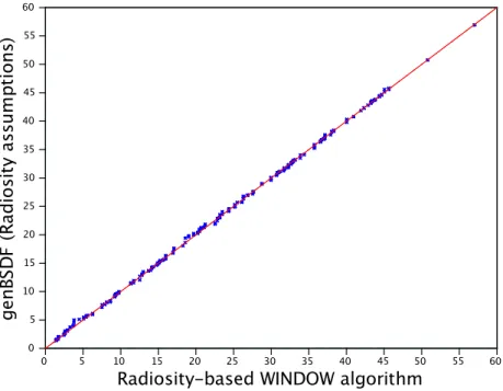
(29) 15. b). The holistic lighting/thermal analysis will be performed using Radiance for the lighting domain and EnergyPlus for the thermal domain. Both software are well known, validated and state-of-the-art tools for their purposes. The connections between them will be made using scripts and informal methods according to proposed workflows, and will be tested by analyzing a theoretical case study. Formal programs will be developed only if strictly necessary. Reasonable results obtained from this methodology will verify hypothesis 2.. 1.6. Thesis structure. Besides this introduction, this thesis is composed of other four chapters, each one of them being an auto-contained potential journal article with their own conclusions, abstract and introduction. Those chapters correspond to (1) a literature review, (2) the evaluation of genBSDF as a tool for assessing the solar bidirectional properties of CFS, (3) the development of a new Radiance based program called mkSchedule that simplifies the holistic thermal/lighting analysis between Radiance and EnergyPlus (or ESP-r, if wanted) and (4) a case study that explains and shows the proposed workflow that allows performing integrated lighting and thermal analysis of buildings with controlled CFS and artificial lighting during the design stage. It should be noted that chapters 3, 4 and 5 are those that validate the hypotheses and accomplish the objectives. While chapter 3 will evaluate Radiance’s genBSDF as a tool for assessing solar BSDF of CFS (proving hypothesis 1 and accomplishing specific objective 1), chapter 4 and 5 accomplish specific objectives 2 and 3, respectively, proving together hypothesis 2. 1.7. Results. In Chapter 3, Radiance’s program, genBSDF, was evaluated as a tool for assessing solar bidirectional properties of CFS. On such chapter, BSDFs of 16 different Venetian Blinds (made of the combination of 4 different positions and 4 different materials) were.
(30) 16. assessed using genBSDF and an analytical model based on the Radiosity method. It is worth saying that, for the modeled CFS, the analytical model provided an outstanding approximation to the exact BSDF. The agreement of both approaches is excellent, obtaining Root Mean Squared Differences of three orders of magnitude less than representative values inside the matrices. Since the ray-tracing techniques (such as the one used by Radiance and genBSDF) have been validated for different geometries and different materials, it is possible to extend the results of genBSDF to any other kind of fenestration systems whose material has optical properties that can be represented by their spectral average (i.e. non spectrally selective material). Chapter 4 consisted on simplifying the holistic thermal and lighting analysis of a space with controlled CFS and artificial lighting, accomplishing the second specific objective. In order to do this, different approaches used on the literature to couple the lighting and thermal domains were studied, and only one methodology was chosen due to its potential to be enhanced and simplified without sacrificing accuracy. The chosen methodology was originally presented by Wienold et al. (2011) consisted on indirectly coupling the thermal and lighting simulation using schedules generated by implementing a control algorithm over the results of multiple Daysim simulation. Such schedules contain the information of the position of the CFS and the power of the luminaires on each simulation timestep. The creation of these schedules was simplified by introducing a new Radiance-based program called mkSchedule. This program utilizes the Threephase method to, simultaneously, carry out efficient annual simulation and implementation of control. Also, a key feature of mkSchedule is that it allows easily defining virtually any control algorithm. From the output of mkSchedule, energy performance simulation can be performed on EnergyPlus or ESP-r, and the lighting simulations can be carried out using Radiance. An important advantage of using mkSchedule is given by the fact that it treats the control algorithms as arguments to the program. Such algorithms are defined in a very simple scripting language, Lua, although the main program is written in C in order to keep time efficiency..
(31) 17. The final chapter proposed a new design workflow that allows performing integrated thermal and lighting analysis of built spaces with controlled CFS and artificial lighting. This workflow uses genBSDF to assess the properties of the Complex Fenestration Systems to be evaluated, mkSchedule program to communicate Radiance and EnergyPlus, which generate the detailed lighting and thermal results, respectively. In summary, chapter 3 proved the first hypothesis, and accomplished the specific objective 1. Chapters 4 and 5, on their part, accomplished the specific objectives 2 and 3, and both together corroborated hypothesis 2. The final product of these research is a methodology that allows evaluating the impact of arbitrary shaped CFS, different luminaire configurations and different control strategies on both the thermal and lighting domain, on early design stages. It must be said that this methodology uses only state-ofthe-art and validated tools. 1.8. Conclusions. From the results of this thesis, it can be concluded that Radiance’s genBSDF program is capable of assessing solar BSDFs of CFS of virtually any geometry if the material properties are known. Using this tool, which performs calculations using ray-tracing techniques, assumptions commonly related to analytical models are no longer required, and expensive equipment needed to carry out laboratory measurement of BSDFs is not needed. In addition to that, since it can deal with CFS of virtually any geometry and materials with any level of specularity, genBSDF is considered the most flexible tool for assessing BSDFs. The major limitation of this methodology is that it assumes that the material optical properties are spectrally averaged. This might not be important in the case of traditional materials, but in the case of spectrally selective materials, the problem would have to be solved by running genBSDF multiple times (on each wavelength range), and then assembling the total solar BSDF. On the other hand, this thesis concluded that it is possible to easily integrate lighting and thermal simulation of spaces with controlled artificial lighting and CFS. This was verified by analyzing a simple case study with controlled Venetian Blinds, whose.
(32) 18. lighting domain was simulated using Radiance, and whose thermal domain was simulated using EnergyPlus. In order to do this, a new Radiance-based program called mkSchedule was developed. This program easily generates schedules that are used to communicate Radiance and EnergyPlus, which assures reliability of results. The proposed approach to integrate Radiance and EnergyPlus is simpler and faster than those studied from literature, and it allows a more flexible and easy way of defining control algorithms. Finally, this thesis showed that the proposed integration methodology can be embedded in a workflow that allows performing integrated lighting and thermal simulations of built spaces during their design stage. This was verified by analyzing a case study that incorporated two sets of dimmable luminaires, a controlled venetian blind and a custom fixed CFS. The results of this methodology, although they were not compared with experimental data, completely agreed with what was expected according to the inputs. In summary, this thesis proposed a complete and simple methodology for designing not only buildings with controlled CFS and artificial lighting, but also their control algorithms, artificial lighting and the CFS themselves. Such methodology is considered to be simple enough to be inserted on a computational tool, and low cost to carry out enough to be directly transferred to industry. It utilizes only state-of-the-art and validated tools and methods, and is focused on the building’s early stages of design. This thesis bridges the gap of designing buildings from a holistic approach. Integrating lighting and thermal simulations, implementing different control algorithms and designing and evaluating shading devices is now a simple process that utilizes only freely available tools such as EnergyPlus and Radiance. 1.9. Perspective and future work. From the workflow proposed in this thesis, the process that is most immature is the assessment of the bidirectional properties using genBSDF. Although the results of this program are outstanding, it is a very time-consuming task that can bother users not used.
(33) 19. to computationally intensive processes. With that respect, it is important to remember that the remaining assumption in this process is that the materials are absolutely gray (not spectrally selective). According to that, CFS made of selective materials will require multiple genBSDF calls in order to analyze small wavelength ranges. According to this, the following future work is proposed: a). Quantify the impact of the non-selective materials assumption.. b). Propose a solution to the problem of spectral selectivity. That could imply finding the best combination of wavelength ranges that provides good results, or developing another tool for assessing BSDFs that is faster (i.e. 2D ray-tracer).. Although the proposed methodology for performing integrated analysis was developed focused on accuracy and simplicity, its results have not compared with in any experimental data, and it has not been used in a real design process which involves larger and more complex buildings with real performance goals. Also, the proposed methodology has not been embedded in any user-friendly tool. According to that, the following future work are proposed on this topic: a). Empirically validate the integrated evaluation methodology.. b). Validate the methodology in a real building design process.. c). Integrate the methodology in a user-friendly tool such as OpenStudio.. Finally, it must be noticed that the Daylight Coefficients, Three-phase and newly presented Five-phase methods perform the actual annual lighting simulations by carrying out simple matrix algebra. According to this, it is very advisable to: a). Enable software like ESP-r and EnergyPlus to read the Radiance-generated matrices, and multiply them within the thermal simulation, which could be the next step towards a perfect thermal/lighting integration.. b). Integrate the Five-phase method into this methodology, and evaluate the time-efficiency and accuracy impacts..
(34) 20.
(35) 21. 2.. LITERATURE REVIEW. 2.1. Abstract. CFS have been defined as those that include a non-specular layer within the glazing assembly. This definition should cover all non-specularly transmitting fenestration system components including layers that provide shading, such as fabric shades and louvered blinds. This systems usually present complex and strong angular dependency on their optical properties, causing that usual indexes as the Solar Heat Gain Coefficient (g-value), the Shading Coefficient, and the Visible Transmittance are no longer representative of the system’s performance, and have to be represented as functions of the incoming and outgoing directions, utilizing the concept of Bidirectional Scattering Distribution Functions (BSDF). On addition to that, they are often installed with the purpose of enhance the visual comfort and energy performance of the building, so making an holistic thermal/lighting analysis is more important than in other cases. Nowadays EnergyPlus and ESP-r are capable of performing thermal simulations considering the complexities of the Complex Fenestration Systems, and the development of the Three-phase and Five-phase methods allow detailed and efficient lighting analysis, including control strategies. Most of these simulations require as input the Bidirectional Scattering Distribution Function in form of matrices, which can be assessed using ray-tracing techniques. 2.2. Introduction. Worldwide, buildings sector consumes more than one fifth of total energy (EIA 2013). This value can vary significantly among countries. For instance, the building sector accounts for around 40% of energy consumption in both the UK (DECC 2013) and the US (stated in October 28th, 2013 in the Buildings Energy Data Book website, of the US Department of Energy), while only for 28.8% in the case of Chile (MinEnergia 2012). The three largest uses of energy in buildings are lighting, heating and cooling. Moreover, people spent over 80% of time inside buildings, which should provide a.
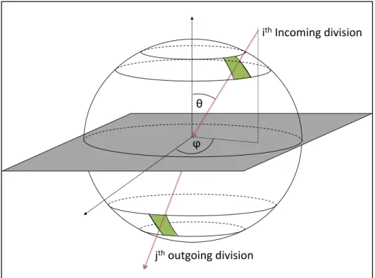
(36) 22. healthy and comfortable indoor environment. Properly designed window systems can cause significant energy savings through reduction of solar gains, which may also improve occupant´s visual and thermal comfort (Wienold et al. 2011; Bessoudo et al. 2010; Tzempelikos et al. 2010; Tzempelikos and Athienitis 2007). The most effective method for reducing solar heat gains on window systems is to block the solar radiation on the external side of them, which could be done by installing shading devices. These devices can be classified in two groups. The first group corresponds to roof overhangs, vertical and horizontal fins and awnings, whereas the second group corresponds to Complex Fenestration Systems (CFS), which include fenestrations attachments that have complex thermal and optical behavior (ASHRAE, 2013) and also all non-specularly transmitting fenestration system components including layers that provide shading. A key characteristic of CFS is that they present complex and strong angular dependency on their optical properties, and they could also show complex convection heat transfer phenomena. These characteristics make them hard to model in thermal and lighting calculations, and make it impossible to classify them using standard performance index. For example, the Shading Coefficient and the normal Solar Heat Gain Coefficient, are no longer representative values of the system’s performance. Despite of this difficulty, these systems are already being installed in dwellings and office buildings all around the world, forcing HVAC and lighting designers to make gross assumptions during the analysis, which could lead to oversize equipment to assure that the thermal and visual comfort is achieved inside the building. CFS are often optically characterized by their Bidirectional Scattering Distribution Functions (BSDF), a concept introduced in (Nicodemus 1970; Nicodemus, Richmond, and Hsia 1977) that can accurately represent the complex radiant behavior of objects. The BSDF of an object can be considered as a mathematical description of how the electromagnetic waves behave when they encounter the object. In the case of CFS, these properties are usually represented in the form of matrices, which are the result of the discretization of the incoming and outgoing semi-hemispheres into “N” directions, resulting in an NxN matrix. Figure 3 shows a representation of the discretization of the.
(37) 23. incoming and outgoing hemispheres in the case of the calculation of the Bidirectional Transmission Distribution Function. (BTDF). These matrices can be specific for a. certain bandwidth in the electromagnetic spectrum. For example, some commonly used bidirectional properties are the solar and visible Transmittances and Reflectances, which are used for energy-performance and daylighting simulations. The most important advantage is that the discretization allows representing virtually any radiant behavior with complete generality. However, the disadvantage is that an incorrect discretization may lead to loss of resolution (i.e. in a single glazing, a specular outgoing lobe might be distributed over an unnecessarily big patch, making the system look as if it was more diffuse than it actually is). This problem can be addressed using a Tensor-tree representation instead of the usual matrix format (Ward, Kurt, and Bonneel 2012), however, this form of representation is less efficient for performing annual simulations. Since fenestration systems are intrinsically related to the thermal and lighting domains, they affect the thermal and lighting performance of buildings. According to this, if one of those domains is optimized without considering the other one, very uncomfortable situations may exist, such as constant glare or overheating. This kind of situations will force the occupants, who will try to remain comfortable, to improvise solutions such as closing the curtains or turning on or off the lights. Even more, Kapsis, O´Brien, & Athienitis (2013) showed that occupants make little effort to control their shades after they initially position them, meaning that the some curtains will practically permanently remain closed if the building’s envelope is not properly designed. However, since the methodologies used for performing lighting and thermal calculations are very different, simulation tools are usually specialized on one of those domains. To improve this situation, some attempts to combine thermal and lighting simulations have been done by artificially communicating two specialized software (Guglielmetti et al., 2011; Wienold et al., 2011)..
(38) 24 I. ith$Incoming$division$. θ$ ϕ$. jth$outgoing$division$ Figure 3: Example of the subdivision of the incoming and outgoing semi-hemispheres. In this chapter, the thermal and lighting domains will be analyzed separately by explaining the methodologies and software available. Then, a section is dedicated to review the attempts of coupling thermal and lighting simulations. 2.3. Thermal Simulations. Thermal simulations are very often used for estimating the energy performance of a building. However, since these tools did not use to be prepared for handling CFS, designers were forced to make gross simplifications. An example of that is (Florides et al., 2000), where the impacts of a Venetian Blind were estimated using TRNSYS, modeling the shading device by dividing the solar transmittance of the Window by approximately half, without considering the strong angular dependences that the solar transmittance of venetian blinds presents. On recent years, two energy-performance simulations tools (EnergyPlus and ESP-r) have been provided with modules that allow simulating the energy performance of spaces with CFS more accurately. On this section, the two different methods that have.
(39) 25. been implemented in these simulation tools are briefly explained. Other software like TRNSYS, DOE-2 or TAS are not included since no information was found on whether they are able to properly handle CFS or how they do it. 2.3.1 Thermal simulation methods for CFS The black-box model Originally presented in (Kuhn, 2006) for facades with venetian blinds or other shading devices, the black-box method can be used as a standalone application, or within a simulation software. This method treats the façade as two layers: the whole glazing unit and the shading device. In order to do so, an angular characterization of both layers is required as well as the calculation of the diffuse optical properties of them. After characterizing both layers, semi-empirical equations are used to combine then and obtain an effective angle-dependent SHGC (g-value). During the simulation, the diffuse radiation is treated by subdividing the sky into 145 patches, according to Tregenza (1987), and the ground is divided into five concentric rings considered lambertian (perfectly diffuse) reflectors. Due to the difficulties involved on using the previous method on simulation programs, a new solution to the same problem was presented on (Kuhn et al., 2011). In this case, the required inputs are the SHGC and the solar transmittance as a function of the angles of incidence (in matrix format), and the U-value (for heat transfer calculations). The advantage of this method is that it takes into account thermal mass, considers the diffuse irradiance from 145 different direction (sky patches) and also allows calculating the center-of-glass U-value. Also, it was developed to be included in energy-performance simulation software..
(40) 26. The EnergyPlus LBNL method This method only applies for the optical side of the CFS (LBNL, 2013a), and the thermal aspects are based on ISO15099 (2003). This methodology relies on the BSDFs of the CFS, and requires various inputs for solar heat gains calculations: front and back Bidirectional Reflectance and Transmittance Distribution Functions (BRDF and BTDF, respectively), and also, one absorption vector for each composing layer, which is used for calculating the absorbed and reemitted component of the solar heat gains. The exterior radiance is separated in two parts: the solar radiance and the sky radiance. The solar radiation is computed, passed through the BTDF of the Complex Fenestration System, and finally assigned to the corresponding receiving interior surfaces. The sky and ground radiation (diffuse), on the other hand, are calculated using average values. Finally, the absorbed and reemitted radiation is spread over the surfaces using view factors, as it is usually done in radiation-heat transfer. An advantage of this method is that it calculates not only how much direct solar radiation is transmitted to the interior but also on which surface is it transmitted to (it does not discriminate between different sections of a surface). This allows better calculations for passive solar design with CFS. However, averaging the sky and ground might generate inaccuracies (Vidanovic, 2013). 2.3.2 Thermal Simulation tools Although whole building simulation programs have daylighting calculation modules, they are mainly focused on the thermal domain. In fact, a survey made on 2008 showed that at that time, even though developers of these tools viewed lighting control as worthy of support, just a few software accepted the full complexity of blinds or translucent facade elements (Crawley, Hand, Kummert, & Griffith, 2008). In general, energy-performance-simulation tools are not well prepared for detailed lighting analysis. Limitations are, for example, visual.
(41) 27. comfort analysis such as the calculation of the Daylight Glare Probability that, for detailed calculations, requires rendering an image (Wienold, 2009). In the following section, a brief review of how these tools can be used for accounting the thermal impacts of CFS. ESP-r ESP-r (ESRU, 2013) is a widely used Energy Simulation Program that is currently capable of handling complex fenestration systems by implementing the black-box model explained earlier (Frontini et al., 2009). The inputs are made via text files that represent the bidirectional characteristics of the system, allowing ESP-r to handle any CFS with consideration of the angular dependency of their optical properties. This tool also allows controlling the CFS in two ways: The first one is by using simulation information (i.e. dry-bulb temperature in any zone or exterior, incident radiation on the external façade, or illuminance), and via Temporal Definition Files (schedules) that can be generated in other software or spreadsheet. EnergyPlus EnergyPlus (Crawley et al., 2001, 2004b) is a building energy simulation program conceived from two previous programs, BLAST and DOE-2. This program is very popular and commonly used, and it is currently capable of simulating spaces with CFS using the EnergyPlus LBNL method (LBNL, 2013a). The capabilities of the EnergyPlus’ CFS module include using a schedule to modify the artificial-lighting internal gains, and modifying (controlling) the CFS using the Energy Management System (EnergyPlus, 2013). 2.4. Lighting simulations. There are two major calculation approaches for estimating the luminance or illuminance levels on a scene: The radiosity method and ray-tracing techniques. However, since these two methods can take a long time for making calculations, they are not very useful.
(42) 28. for dynamic simulations. That is the reason why in this document a distinction is made between static simulation methods (i.e. ray-tracing techniques and the Radiosity method) and dynamic simulations methods. While the first group is used to make calculations of instant moments (for example, rendering photorealistic images), the latter are focused on yearly simulations. 2.4.1 Static simulation methods As mentioned earlier, the two main algorithms for calculating lighting levels are the Radiosity method and the ray-tracing techniques. In this section, however, another two static simulation methods, BTDF2prism2 and mkillum, have been included that intend to accelerate the ray-tracing calculations specifically in spaces that include CFS. Radiosity method This method was derived from those used in thermal engineering, and represents a fundamental energy equilibrium (Greenberg et al., 1986). With the Radiosity method, the space is divided into a mesh of patches that are considered Lambertian reflectors (perfect diffusers), thus the specular reflection (i.e. light redirecting fenestration system) cannot be treated effectively (Tsangrassoulis & Bourdakis, 2003). As in the thermal engineering methods, view factors must be computed and large matrix problem solving is needed for calculating the luminance or illuminance levels in the scene. Therefore, computing cost grows fast with the number of patches considered, which happens when the scene becomes more complicated. Ray-tracing techniques Ray-tracing methodologies can deal more easily with complex building forms, because they do not require the calculation of view factors. In this method, light rays are emitted from light sources (forward ray-tracing) and striking surfaces, or followed from the reception point into the scene (backward ray-tracing). Each ray.
(43) 29. carries a weight which is proportional to the intensity of the corresponding ray. When the weight of one ray falls below an arbitrary value, it is taken to be absorbed and the process is repeated with a new emission (Tsangrassoulis & Bourdakis, 2003). These techniques can be thought as direct simulation of light transfer on a scene. However, many different approaches are often used in order to accelerate calculations (i.e. forward or backward ray-tracing), and optimize simulation of specific situations. The BTDF2prims2 procedure This procedure was developed with the purpose of integrating bidirectional information of CFSs in Radiance (Ward, 1994) lighting simulation tool (Kaempf & Scartezzini, 2004). It utilizes the BSDF of the CFS to build a Radiance material that is based on the prism2 Radiance primitive. This allows modeling the measured system as one surface with a specific material that is automatically generated instead of inputting the whole geometry and materiality. The BTDF2prism2 procedure is summarized in (Kaempf & Scartezzini, 2004) as the following four steps: First, monitored BTDF data is transformed into transmission coefficients (directional-directional). Second, the two prevailing emerging directions of light are identified (thus, this method is not applicable to highly diffuse CFS). Third, a transmission coefficient is attributed to each pair of transmission peak (i.e. the first peak of the 38th incoming direction of a 3M prismatic film transmits 35.2% and the second one 11%). Finally, according to the gravity center of each peak, a spherical angular coordinate is attributed to each transmission peak. This routine allows an excellent representation of specular CFS that have two main directions. However, it is not good for CFS that do not fall on that group (i.e. CFS with an important diffuse component)..
Figure

+7


Documento similar
No obstante, como esta enfermedad afecta a cada persona de manera diferente, no todas las opciones de cuidado y tratamiento pueden ser apropiadas para cada individuo.. La forma
It is generally believed the recitation of the seven or the ten reciters of the first, second and third century of Islam are valid and the Muslims are allowed to adopt either of
In the preparation of this report, the Venice Commission has relied on the comments of its rapporteurs; its recently adopted Report on Respect for Democracy, Human Rights and the Rule
H I is the incident wave height, T z is the mean wave period, Ir is the Iribarren number or surf similarity parameter, h is the water depth at the toe of the structure, Ru is the
In the previous sections we have shown how astronomical alignments and solar hierophanies – with a common interest in the solstices − were substantiated in the
What is perhaps most striking from a historical point of view is the university’s lengthy history as an exclusively male community.. The question of gender obviously has a major role
The purpose of the research project presented below is to analyze the financial management of a small municipality in the province of Teruel. The data under study has
“ CLIL describes a pedagogic approach in which language and subject area content are learnt in combination, where the language is used as a tool to develop new learning from a
