Effects of Frequency Dependence of the External Quantum Efficiency of Perovskite Solar Cells
12
0
0
Texto completo
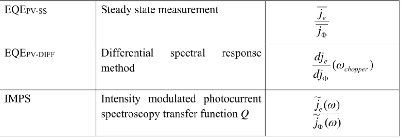
(2) 2. The external quantum efficiency (EQE) is a central characterization tool to estimate the performance of a photovoltaic cell. It is defined as the ratio of number of collected electron-hole pairs to the number of photons impinging on the device.1 The EQE provides information on how efficiently the solar cell is able to absorb a photon, generate an electron-hole pair, separate and subsequently extract these carriers at respective selective contacts. It can also provide device parameters such as the short-circuit current (Jsc) and in some cases even the diffusion length, depending upon the dominant transport mechanism. An example being the diffusion-recombination model for dye sensitized solar cells2 which allows discerning transport from recombination time. Traditionally, the EQE is measured at short circuit (SC) by applying a monochromatic AC small perturbation in light intensity and measuring the response of the solar cell, subsequently scanned over the range of wavelengths of incoming light. The solar cell is kept under a DC biasing white light intensity that can range from 5 -100 mWꞏcm-2 during the measurement,3 although in most cases of collection efficiency measurements, the bias intensity is very low, between 5-10 mWꞏcm-2,4,5 whose main purpose is to provide a small background charge density to raise the conductivity of the solar cell from its minimal dark value. The modulation frequency of the AC small perturbation in light intensity is determined by an optical chopper6 and is assumed to be much lower (a few hundred Hz)7-9 than the frequency associated with the processes of carrier generation, transport, recombination (lifetime) and charge storage mechanisms, and hence should not have an influence on the measured EQE. However, the validity of this assumption is not assured in the case of perovskite solar cells (PSCs). PSCs are known to show responses at very long timescales in the order of milliseconds to seconds, observed in both voltage and current evolution, which has been confirmed from a wide variety of experiments such as open-circuit voltage (Voc) decay,10 stepped voltage scans11 and current decay from photoinduced charge extraction (PI-CE) measurements.12 This has also been observed in the EQE, which has been seen to evolve over timescales of minutes in both dark and light conditions,11,13 making the estimation of the Jsc very difficult.14 Furthermore, a large capacitance of the order of mF cm-2 has been observed from impedance spectroscopy (IS) measurements at SC,15 similar in magnitude to that observed at open-circuit (OC) conditions,16 which is likely related to the aforementioned EQE evolution. Therefore, a clarification regarding the nature of EQE evolution in perovskites and its contributing factors is required to better understand its operation and limiting mechanisms at SC and ascertain the validity of the EQE obtained at a given state of the perovskite solar cell. We first provide a general definition of the EQE as obtained from standard experimental practices. Let je be the extracted photocurrent density while the maximal current density j q is defined from , the input photon flux at a given wavelength , and q the elementary charge. The steady state EQE, EQEPV-SS, is (1) j. EQEPV SS . e. j. The overhead bars indicate conditions of steady state. A traditional experimental.
(3) 3. method termed the differential spectral response method, EQEPV-DIFF, involves the measurement of the photocurrent at SC upon application of a small low frequency AC perturbation of monochromatic light (using an optical chopper) to the sample, which is illuminated by a DC bias white-light intensity.. Under an applied small perturbation of ~ ~ light intensity j j j , we can write je je je ,. ~j d je EQEPV DIFF ~e j d j. (2). Equation 2 is an approximation because it assumes an infinitely slow (zero frequency) perturbation, while realistic measurements involve frequencies in the range of a few hundred Hz imparted by the optical chopper. For the sake of generality, a power-law relationship can describe the most common dependences of collected current on photon flux as:. j e ( ) k j ( ) n. (3). where n accounts for a power-law exponent and k is a proportionality constant. This is because we are normally interested in the variation of EQE over several decades of photon flux from which n is readily derived. Thus we have. EQEPV DIFF nk j. n 1. (4). We also corroborate the EQEPV-DIFF values with IMPS measurements, which involve the measurement of modulated extracted photocurrent versus modulated input photon current density. The transfer function of IMPS is given by17. ~j ( ) Q( ) ~e j ( ). (5). . Because of the modulated character of both input and output signals, one can expect inphase and out-of-phase components of the transfer function, similarly to that occurring when measuring impedance spectroscopy. This implies the complex (real and imaginary) form of the IMPS measurement so that Q = Q’ + iQ’’, whose low-frequency limit is purely real and it is given by. Q(0) . d je d j. (6). which corresponds to the definition in Equation 2 provided that = 0. Therefore, the EQEPV-DIFF value ideally approximates the low frequency limit of the IMPS transfer function. We note that the measurement of EQEPV-DIFF from direct measurements (differential spectral response method) and from IMPS measurements are identical in the sense that they are both small perturbation methods, the only difference being that the AC perturbation in direct measurements is generated using an optical chopper with the incident light beam, whereas the AC light perturbation in IMPS is generated by driving an AC current through the light source using a potentiostat. In both cases, it is ensured.
(4) 4. that the light perturbation acting on the solar cells is the same in the full range of light intensities and frequencies. The other difference is in their application, since IMPS is usually considered as a frequency-resolved method to obtain kinetic information. However, from the point of view of EQE analysis, we can use both approaches in combination. The above mentioned definitions are summarized in Table 1. By comparing Equations 1 and 4, we can see that the values of EQE obtained from small-perturbation methods and steady-state methods converge only if the relationship between extracted photocurrent and input photon flux is linear. Table 1 Definition of external quantum efficiency according to the measurement procedure. In the differential spectral response method, the output is a function of the optical chopper frequency, as indicated. EQEPV-SS. Steady state measurement. EQEPV-DIFF. Differential method. IMPS. Intensity modulated photocurrent spectroscopy transfer function Q. spectral. je j response. dje ( chopper ) dj ~ je ( ) ~ j ( ). We now proceed to identify the trends of EQE evolution with input photon current density in perovskite solar cells and to clarify the above described methods of EQE measurement. Figure SI1a and SI1b show the J-V curve of the perovskite solar cell tested and its corresponding maximum photocurrent. In addition to measuring EQEPV-DIFF directly, we also obtain the value indirectly using the following methods. The first method involves determination of EQEPV-SS from steady state measurements of extracted photocurrent density for a given input photon current density. We then obtain EQEPV-DIFF from the slope of the data obtained from the steady state measurements, as shown in Equation 2. The second method involves measurement of IMPS spectra and extracting the EQEPV-DIFF value, which corresponds to the low-frequency limit of the transfer function, as shown in Equation 6. Both EQEPV-SS and IMPS measurements were carried out using a blue light (470 nm) source in order to avoid effects relating to absorption losses (see Figure SI2 for absorption spectrum)..
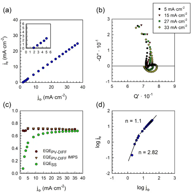
(5) 5. Figure 1 (a) Evolution of extracted photocurrent versus input photon current density from steady state measurements (the inset shows the low intensity region) (b) IMPS spectra for different DC bias blue light intensities expressed as current density as shown in legend. (c) Evolution of EQE as defined from small perturbation methods (EQEPV-DIFF), obtained from steady state measurements (red) and IMPS (orange), and steady state method (green) (EQEPV-SS). (d) log-log plot of data in (a) to obtain the exponent n in Equation 3. All measurements carried out with monochromatic radiation of wavelength 470 nm. Figure 1a shows the evolution of steady state extracted photocurrent versus photon current density, from which the values of EQEPV-SS and EQEPV-DIFF are calculated, shown in Figure 1c. While EQEPV-SS values show a gradual rise to reach a constant value, the EQEPV-DIFF values are almost constant through the entire range of photon current densities. It can be seen that the values of EQEPV-DIFF and EQEPV-SS converge to similar values only.
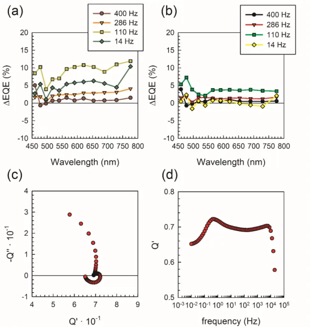
(6) 6. at high photon current densities. Since EQE measurements are usually carried out at low light intensities (and hence photon current densities), it is clear that the values of EQE will be quite different depending on the employed measuring method. Figure 1b shows the corresponding IMPS spectra of the perovskite solar cell obtained at different photon current densities. The spectra typically show two arcs in the upper quadrant, corresponding to high and intermediate frequencies, followed by a low-frequency arc in the lower quadrant, whose origins are discussed later on. For now, we observe that the low frequency limit of the IMPS spectra matches quite nicely with the values of EQEPVDIFF obtained from the slope of the steady state measurements as seen in Figure 1c. As mentioned earlier, the divergence in values of EQEPV-DIFF and EQESS depend on the exponential factor n in Equation 1. This factor is obtained from a log-log plot of je versus j , shown in Figure 1d. We can clearly distinguish two regimes of behavior. The first regime occurs at low photon current densities, where the relationship is highly non-linear with n 2 .8 , while at higher photon current densities, the evolution is almost linear with n 1 .1 . Therefore, the values of EQEPV-DIFF and EQESS collapse only at higher photon current densities. The existence of these regimes can be attributed to the strong photoconductive behavior in perovskites. At high light intensity, a linear behavior is observed as expected, but the low conductivity values near dark conditions18,19 reduces charge collection and photocurrent values, so that the strong non-linear dependence at low light intensities (in Fig. 1e) is likely influenced by collection efficiency issues. We now proceed to clarify the validity of Equation 2 for perovskite solar cells by measuring the effect of the optical chopper frequency on the EQEPV-DIFF values. The EQEPV-DIFF was measured with and without DC white light bias at five different optical chopper frequencies of 500, 400, 286, 110 and 14 Hz. Figure 2a and 2b shows the variation in EQEPV-DIFF without and with a 10 mWꞏcm-2 DC white light bias at a given frequency of the optical chopper with respect to the values at 500 Hz, which is used as reference. We observe that the EQEPV-DIFF increases upon lowering the optical chopper frequency in both cases, with a maximum increment of 8-10% in EQEPV-DIFF from 500 Hz to 110 Hz. At lower frequencies (14 Hz) the EQEPV-DIFF drops. This strong frequency dependence describing a response peak is also reflected in the IMPS spectra of Figure 2c that shows high frequency and intermediate arcs in the first quadrant followed by a low frequency arc in the fourth quadrant. The evolution of the real part of the IMPS transfer function is shown in Figure 2d. It shows a maxima at high frequency (~104 Hz) and another at low frequency (~ 1Hz), with very little evolution in between. After the second maxima, it then drops sharply for very low frequencies. It is then evident that both techniques (EQEPV-DIFF and IMPS) exhibit similar evolution with the perturbation frequency. This is because EQEPV-DIFF and Q’, the real part of IMPS, provides information on the effective extracted photocurrent at a given perturbation frequency..
(7) 7. Figure 2 Variation in EQEPV-DIFF at (a) 0 DC white light bias and (b) 10 mWꞏcm-2 DC white light bias for different optical chopper frequencies with respect to spectra measured at 500 Hz. (c) IMPS spectra measured at 33 mAꞏcm-2 DC blue light bias and (d) Evolution of real part of IMPS transfer function versus frequency at 470 nm. In general, the value of EQEPV-DIFF obtained from direct measurements is in fact the real part of the IMPS transfer function at the given optical chopper frequency, as mentioned earlier. For the simplest model of a solar cell, consisting of a recombination resistance ( Rrec ) and a chemical capacitance ( C ) coupled in parallel with a current source, and a series resistance ( Rs ), the IMPS response is an arc in the upper quadrant and the real part of the IMPS transfer function is a frequency-dependent process, containing the ratio between the frequency associated to the time constant Rs C and the applied frequency (see SI for derivation). In this case,.
(8) 8. Q( ) . Q(0) 1 Q(0) 2 ( / ) 2. (7). where the low frequency intercept has the value. Q(0) (1 . Rs 1 ) Rrec. (8). This can be understood by observing the equivalent circuit of the simple solar cell model at SC shown in Figure 3a, with a current source corresponding to photogenerated carriers in parallel to both the recombination resistor and the chemical capacitor. The IMPS response can be viewed similar to an RC attenuator, where the capacitor controls the frequency-dependent response of the extracted photocurrent through the series resistance.20 Therefore, the IMPS arc is the attenuation of the total photocurrent through the equipotential lines in the circuit. At higher frequencies, the capacitor acts as a short circuit and reduces the flow of current through the series resistance, while at low frequencies, the capacitor behaves as a blocking element and the total current through the series resistance is determined simply by the ratio of magnitudes of the series resistance and the recombination resistance. Therefore, the real part of the IMPS transfer function and hence the EQEPV-DIFF has a maximum at zero frequency corresponding to Equation 8 and reduces with increasing frequency for the simple solar cell model. This leads to the important fact that the EQEPV-DIFF can be frequency independent only when the frequency associated with the time constant Rs C is much larger than the optical chopper frequency employed..
(9) 9. Figure 3 IMPS response at SC and corresponding equivalent circuit for (a) basic solar cell model and (b) perovskite solar cell. In perovskite solar cells, the IMPS spectra in Figure 1b deviate from the previous simple model, with the observation of a distinctive low frequency arc in the lower quadrant. The high frequency arc can be attributed, as explained earlier, to the time constant formed by the series resistance and a high frequency capacitor,21 as shown in the equivalent circuit of Figure 3b, which corresponds to that commonly used to analyze impedance spectroscopy responses.15 The high-frequency capacitance is well established to be the bulk dielectric capacitance of the perovskite.16 The IMPS low-frequency arc is related to the components in the equivalent circuit as far as the generation of carriers is located exclusively across the high frequency resistor Rhf , as calculated using standard electrical network analysis. This creates a delay in the extracted photocurrent through the low-frequency capacitance Clf with respect to the photogenerated current, leading to a response in the lower quadrant. At the low-frequency limit, the separated localization of the current source forces the resistor Rlf to act identically as an extra series resistor, which can be seen simply as the basic solar cell model with a net series resistance of Rnet Rs Rlf . This reduces the value of EQEPV-DIFF as can be seen from Equation 8, which causes the arc in the fourth quadrant to evolve towards lower EQEPV-DIFF values at lower frequencies. Therefore, the evolution of the magnitude of the low-frequency resistor Rlf with light intensity is crucial to determine the achievable low frequency EQEPV-DIFF values. It must be noted that the large low frequency capacitance associated with this resistor in the order of mF cm-2 at SC15 has recently been ascribed to the accumulation of minority electrons and anions at the perovskite/HTL interface.22 Therefore, a further understanding of the properties of the low frequency resistor and capacitor are fundamental to understanding the nature of the EQEPV-DIFF in perovskite solar cells. In summary, some years back, the drift of efficiencies of perovskite solar cells by hysteresis effects could be identified. An ensuring point to a reliable measurement of performance is to calculate the expected photocurrent from independent EQE measurement. But here, we show that the latter effect can produce a disparity of results. To clarify the question, we provided formal definitions of the EQE for solar cells as can be obtained from steady state measurements or from small perturbation methods. The obtained values can vary strongly from each other depending on the linearity of the relationship between the extracted photocurrent and the input photon flux. The extremely slow response in timescale of seconds of perovskite solar cells at short circuit is inevitably reflected in small perturbation EQE measurements, where variations as high as 10% can be obtained with optical chopper frequencies in the range of 10-500 Hz. Through IMPS measurements, we shed light on the frequency-dependent evolution of the external quantum efficiency, which reaches a maximum at intermediate frequencies followed by a reduction at low frequencies. This low frequency effect is ascribed to the differences in charge generation within the perovskite solar cell. Due to the singular evolution of the.
(10) 10. EQE, it is imperative to establish protocols and to provide detailed information regarding the method of measurement. Measurements with several optical chopper frequencies, stated explicitly, are recommended to avoid erroneous estimation of the true EQE. Acknowledgements We acknowledge funding from MINECO of Spain under project MAT2016-76892C3-1-R and MAT2016-76892-C3-2-R. P.P.B. thanks MINECO for his post-doctoral RyC contract and acknowledges financial support from the Conselleria d’Educació Investigació, Cultura i Esport, Generalitat Valenciana (SEJI2017/2017/012). References (1) Bisquert, J. The Physics of Solar Cells: Perovskites, Organics, and Photovoltaic Fundamentals. CRC Press, Boca Raton, FL, 2018. (2) Soedergren, S.; Hagfeldt, A.; Olsson, J.; Lindquist, S.-E. Theoretical Models for the Action Spectrum and the Current-Voltage Characteristics of Microporous Semiconductor Films in Photoelectrochemical Cells. J. Phys. Chem. 1994, 98, 5552-5556. (3) Thomas, J. K. B.; Yana, V.; Zhe, L.; Dinesh, K.; Richard, H. F.; Christopher, R. M. White-Light Bias External Quantum Efficiency Measurements of Standard and Inverted P3HT : PCBM Photovoltaic Cells. J. Phys. D 2012, 45, 415101. (4) Li, X.; Bi, D.; Yi, C.; Décoppet, J.-D.; Luo, J.; Zakeeruddin, S. M.; Hagfeldt, A.; Grätzel, M. A Vacuum Flash–Assisted Solution Process for High-Efficiency LargeArea Perovskite Solar Cells. Science 2016, 353, 58-62. (5) Tan, H.; Jain, A.; Voznyy, O.; Lan, X.; García de Arquer, F. P.; Fan, J. Z.; Quintero-Bermudez, R.; Yuan, M.; Zhang, B.; Zhao, Y.; Fan, F.; Li, P.; Quan, L. N.; Zhao, Y.; Lu, Z.-H.; Yang, Z.; Hoogland, S.; Sargent, E. H. Efficient and Stable SolutionProcessed Planar Perovskite Solar Cells via Contact Passivation. Science 2017, 355, 722. (6) Cowan, S. R.; Wang, J.; Yi, J.; Lee, Y.-J.; Olson, D. C.; Hsu, J. W. Intensity and Wavelength Dependence of Bimolecular Recombination in P3HT: PCBM Solar Cells: A White-Light Biased External Quantum Efficiency Study. J. Appl. Phys. 2013, 113, 154504. (7) Tsai, H.; Asadpour, R.; Blancon, J.-C.; Stoumpos, C. C.; Durand, O.; Strzalka, J. W.; Chen, B.; Verduzco, R.; Ajayan, P. M.; Tretiak, S.; Even, J.; Alam, M. A.; Kanatzidis, M. G.; Nie, W.; Mohite, A. D. Light-Induced Lattice Expansion Leads to High-Efficiency Perovskite Solar Cells. Science 2018, 360, 67. (8) Bush, K. A.; Palmstrom, A. F.; Yu, Z. J.; Boccard, M.; Cheacharoen, R.; Mailoa, J. P.; McMeekin, D. P.; Hoye, R. L. Z.; Bailie, C. D.; Leijtens, T.; Peters, I. M.; Minichetti, M. C.; Rolston, N.; Prasanna, R.; Sofia, S.; Harwood, D.; Ma, W.; Moghadam, F.; Snaith, H. J.; Buonassisi, T.; Holman, Z. C.; Bent, S. F.; McGehee, M. D. 23.6%-.
(11) 11. Efficient Monolithic Perovskite/Silicon Tandem Solar Cells with Improved Stability. Nat. Energy 2017, 2, 17009. (9) Nie, W.; Tsai, H.; Blancon, J. C.; Liu, F.; Stoumpos Costas, C.; Traore, B.; Kepenekian, M.; Durand, O.; Katan, C.; Tretiak, S.; Crochet, J.; Ajayan Pulickel, M.; Kanatzidis Mercouri, G.; Even, J.; Mohite Aditya, D. Critical Role of Interface and Crystallinity on the Performance and Photostability of Perovskite Solar Cell on Nickel Oxide. Adv. Mater. 2017, 30, 1703879. (10) Gottesman, R.; Lopez-Varo, P.; Gouda, L.; Jimenez-Tejada, J. A.; Hu, J.; Tirosh, S.; Zaban, A.; Bisquert, J. Dynamic Phenomena at Perovskite/Electron-Selective Contact Interface as Interpreted from Photovoltage Decays. Chem 2016, 1, 776-789. (11) Unger, E.; Hoke, E.; Bailie, C.; Nguyen, W.; Bowring, A.; Heumüller, T.; Christoforo, M.; McGehee, M. Hysteresis and Transient Behavior in Current–Voltage Measurements of Hybrid-Perovskite Absorber Solar Cells. Energy Environ Sci. 2014, 7, 3690-3698. (12) O’Regan, B. C.; Barnes, P. R. F.; Li, X.; Law, C.; Palomares, E.; MarinBeloqui, J. M. Optoelectronic Studies of Methylammonium Lead Iodide Perovskite Solar Cells with Mesoporous TiO2: Separation of Electronic and Chemical Charge Storage, Understanding Two Recombination Lifetimes, and the Evolution of Band Offsets during J–V Hysteresis. J. Am. Chem. Soc. 2015, 137, 5087-5099. (13) Samu, G. F.; Janáky, C.; Kamat, P. V. A Victim of Halide Ion Segregation. How Light Soaking Affects Solar Cell Performance of Mixed Halide Lead Perovskites. ACS Energy Lett. 2017, 2, 1860-1861. (14) Lopez‐Varo, P.; Jiménez‐Tejada, J. A.; García‐Rosell, M.; Ravishankar, S.; Garcia‐Belmonte, G.; Bisquert, J.; Almora, O. Device Physics of Hybrid Perovskite Solar Cells: Theory and Experiment. Adv. Energy Mater. 2018, DOI: 10.1002/aenm.201702722 (15) Zarazua, I.; Han, G.; Boix, P. P.; Mhaisalkar, S.; Fabregat-Santiago, F.; Mora-Seró, I.; Bisquert, J.; Garcia-Belmonte, G. Surface Recombination and Collection Efficiency in Perovskite Solar Cells from Impedance Analysis. J. Phys. Chem. Lett. 2016, 7, 5105-5113. (16) Almora, O.; Zarazua, I.; Mas-Marza, E.; Mora-Sero, I.; Bisquert, J.; GarciaBelmonte, G. Capacitive Dark Currents, Hysteresis, and Electrode Polarization in Lead Halide Perovskite Solar Cells. J. Phys. Chem. Lett. 2015, 6, 1645-1652. (17) Bertoluzzi, L.; Bisquert, J. Investigating the Consistency of Models for Water Splitting Systems by Light and Voltage Modulated Techniques. J. Phys. Chem. Lett. 2016, 8, 172-180. (18) Chen, Y.; Yi, H.; Wu, X.; Haroldson, R.; Gartstein, Y.; Rodionov, Y.; Tikhonov, K.; Zakhidov, A.; Zhu, X.-Y.; Podzorov, V. Extended Carrier Lifetimes and.
(12) 12. Diffusion in Hybrid Perovskites Revealed by Hall Effect and Photoconductivity Measurements. Nat. Commun. 2016, 7, 12253. (19) Wang, F.; Mei, J.; Wang, Y.; Zhang, L.; Zhao, H.; Zhao, D. Fast Photoconductive Responses in Organometal Halide Perovskite Photodetectors. ACS Appl. Mater. Interfaces 2016, 8, 2840-2846. (20) Ponomarev, E.; Peter, L. A Generalized Theory of Intensity Modulated Photocurrent Spectroscopy (IMPS). J. Electroanal. Chem. 1995, 396, 219-226. (21) Pockett, A.; Eperon, G. E.; Peltola, T.; Snaith, H. J.; Walker, A.; Peter, L. M.; Cameron, P. J. Characterization of Planar Lead Halide Perovskite Solar Cells by Impedance Spectroscopy, Open-Circuit Photovoltage Decay, and Intensity-Modulated Photovoltage/Photocurrent Spectroscopy. J. Phys. Chem. C. 2015, 119, 3456-3465. (22) Garcia-Rosell, M.; Bou, A.; Jiménez-Tejada, J. A.; Bisquert, J.; Lopez-Varo, P. Analysis of the Influence of Selective Contact Heterojunctions on the Performance of Perovskite Solar Cells. J. Phys. Chem. C. 2018, DOI: 10.1021/acs.jpcc.8b01070.
(13)
Figure
Documento similar
In the preparation of this report, the Venice Commission has relied on the comments of its rapporteurs; its recently adopted Report on Respect for Democracy, Human Rights and the Rule
Each figure shows the steady state availability un- der a different combination of workload rate and time-out duration.. (a) low workload, short time-out (b) low workload,
No obstante, como esta enfermedad afecta a cada persona de manera diferente, no todas las opciones de cuidado y tratamiento pueden ser apropiadas para cada individuo.. La forma
(inset) Axis detail showing coercivity dependence of the magnetic material for increasing amount of internalized Co nanoparticles... Figure 5 XAS spectra of the Co references and
Dependence of Halide Composition on the Stability of Highly Efficient All-Inorganic Cesium Lead Halide Perovskite Quantum Dot Solar Cells. Surface Trap States Passivation for
• Telemetry processor will use a look-up table, initially populated by values obtained in simulation, to update the control loop gains based on its r 0 and noise variance
Díaz Soto has raised the point about banning religious garb in the ―public space.‖ He states, ―for example, in most Spanish public Universities, there is a Catholic chapel
The independent variables that best relate to the bulk density of metallic pieces produced by selective laser melting and are therefore included in the dimensional analysis
