1
Escuela Técnica Superior de Ingenieros de
Caminos, Canales y Puertos.
UNIVERSIDAD DE CANTABRIA
ALTERNATIVE ANALYSIS IN SOFT-SOFT DESIGN FOR
ONSHORE WIND TURBINE HYBRID TOWERS FOR FUTURE
PROGRESSIVE HEIGHTS
ANÁLISIS DE ALTERNATIVAS EN EL DISEÑO “SOFT-SOFT”
DE TORRES DE AEROGENERADORES EN TIERRA PARA
ALCANZAR MAYORES ALTURAS
Author:
Fedelis Chek AWEH
Supervisor:
Pr. Francisco Ballester
Co-supervisor:
Jokin Rico
University Degree:
Master in Construction Research, Technology and
Management in Europe – Máster en Investigación,
Tecnología y Gestión de la Construcción en Europa
Santander, September 2017
T
R
A
B
A
J
O
F
IN
D
E
M
Á
S
T
E
R
2
ABSTRACT
The national renewable energy laboratory (NREL) through its researchers, advocated to reach tall winds with tall towers to enable continuous plant performance Improvements. This will cause an increase in clean energy production to satisfy the exponential demand.
One of the difficulties faced by NREL and the wind energy industries at large, is providing the necessary supporting structure to reach tall winds and support the production machineries. Supporting structures have been developed in the past, but it faces constrains today from structural stability and cost as it advocates to increase into the high winds.
Some of the constraints within structural stability and cost are the main core of this research work. A battery of hybrid concrete-steel towers with variable heights were being analyzed in two different ways to obtain soft-soft hybrid towers. Soft-soft hybrid towers are the most cost-effective towers with higher abilities to move up to tall winds. The natural frequency of an installed wind turbine tower determines its characteristics (soft-soft, soft-stiff, stiff-stiff) under maximum operations. The two-careful analysis was carried out under the following dimensional characteristics of the hybrid towers in a constant environmental condition;
1) Increasing the bottom concrete diameter with different concrete wall thickness and a constant steel height for different hub heights.
2) Vary the concrete and steel heights with a constant wall thickness for steel and concrete. Observing the results, it was shown that; soft-soft hybrid wind turbine towers have a greater ability of growing to higher height with a reduced concrete wall thickness and base concrete diameter. The cost of transportation is favorable due the reduced diameter and weight of steel panels.
3
ACKNOWLEDGEMENTS
I do express my immerse appreciation and acknowledgement to Professor Francisco Ballester for creating such a lucrative research opportunity for my participation. His presence during these research works gave me innovative ideas for future professionalism. He introduced the whole wind energy concept to me through well explicit presentations. His published articles were of great assets to this research work. Dr. Jokin Rico is one of the fore architects during this research work which I do acknowledge his contributions. His unique psychological method of appeasing difficult and stressful moments during this research work worth acknowledging. He was responsible to set milestone objectives and verify results. During the research work, he proposes other methods of going about the research when faced with difficulties. Silvia Suarez is an inspired civil engineer with the decent wisdom of coordinating my day to day research work activities. She was responsible to educate the basic notions with detailed demonstrations in a progressive manner along the research work. With her simple methods of explaining bigger things, it gave me the alluring view about the whole research work and constantly working with her. Acknowledging her great contribution begins from my first day in the office to the last day of submitting. Her charismatic teaching value and mastery of the subject matter, let me into divers understanding to research more in the near future. I also do here hereby acknowledge Marcos Cerezo for his fervent support during this work. He took up tireless moments to explain the basic knowledge of using MIDAS software used in the methodology of this work. His attention to, answer worries and encouragement cannot be undermined. I generally acknowledge the friendly-learning environment of INGECiD company and particularly Ana Mayordomo Jenaro at Cantabria university for the provision of the necessary logistics during this research project.
4 TABLE OF CONTENTS ABSTRACT ... 2 ACKNOWLEDGEMENTS ... 3 TABLE OF CONTENTS ... 4 LIST OF FIGURES/GRAPHS... 6
LIST OF TABLES (including appendix tables)... 8
LIST OF ABBREVIATIONS / SYMBOLS / EQUATIONS ... 9
1. INTRODUCTION ... 10
1.1. BACKGROUND AND PROBLEM DESCRIPTION ... 10
1.2. AIMS & OBJECTIVES ... 14
1.3. WORK/RESEARCH METHODOLOGY AND LIMITATIONS ... 15
1.4. SCOPE ... 16
1.5. STRUCTURE OF THIS REPORT ... 16
2. STATE OF THE ART ... 17
2.1. INTRODUCTION ... 17
2.2. NACELLE ... 20
2.3. HUB ... 20
2.4. BLADES ... 21
2.5. WIND TURBINE TOWERS ... 23
2.5.1. Hybrid wind turbine towers ... 24
2.5.2. Modal analysis of wind turbine towers ... 24
2.5.3. Materials and geometry commonly used for wind turbine towers ... 25
2.6. FOUNDATION ... 27
3. BASIS OF DESIGN AND METHODOLOGY... 31
3.1. BASIS OF DESIGN ... 31
3.1.1. Hybrid concrete tower ... 31
3.1.2. Concrete tower geometry ... 31
3.1.3. Tower main characteristics ... 34
3.1.4. Rotor and nacelle data ... 39
3.2. APPLICATION OF MODAL ANALYSIS FOR SOFT-SOFT DESIGN ... 39
5
3.4. SIMULATION ... 40
3.5. PROCEDURE OF SIMULATING A MODEL AND MODAL ANALYSIS PERFORMANCE ... 40
3.5.1. Creating an interface ... 40
3.5.2. Creating materials and sections ... 42
3.5.3. Creating a structural model (Simulation)... 44
3.5.4. Assigning loads and boundary conditions ... 45
3.5.5. Analyzing and verifying results ... 48
4. RESULTS ... 49 4.1. INTRODUCTION ... 49 4.2. CASE 1 ... 49 4.2.1. Concrete thickness 0.35 m ... 49 4.2.2. Concrete thickness 0.40 m ... 50 4.2.3. Concrete thickness 0.45 m ... 51 4.2.4. Analysis of results ... 52 4.3. CASE 2 ... 53 4.3.1. CASE 2 RESULT ... 53 4.3.2. Summary of results ... 53 4.3.3. Analysis of results ... 54 4.4. CONCLUSIONS ... 55 4.5. REFERENCES ... 56 4.6. ANNEXES ... 58
4.6.1. CASE 1 Spread Sheet 0.35m ... 58
4.6.2. CASE 1 Spread Sheet 0.4m ... 59
4.6.3. CASE 1 Spread Sheet 0.45m ... 60
4.6.4. Graph Representation e=0.35m ... 61
4.6.5. Graph representation e=0.40m ... 62
4.6.6. Graph Representation e=0.45 ... 63
4.6.7. Model Eigenfrequency Reaction Case 1 ... 64
6 LIST OF FIGURES/GRAPHS
Figure 1: Magnitude of Pressure Gradient ... Figure 2: Coriolis Force Variations Across Earth ...
Figure 3: Isobar ... 11
Figure 4: Intower in rotor size and towers height from 1, 80 to the present (Wiser,Yang et Al.) ... 11
Figure 5: Summary of tower alternatives for 3 MW wind turbines ... 12
Figure 6: Tower mass (t) – Hub height (m) (NREL) ... 13
Figure 7: Lattice tower (left). LDST (right). ... 14
Figure 8: Spiral-welded towers ... 14
Figure 9: Location of Horizontal (HAWT) & Vertical (VAWT) Axis Wind Turbine ... 17
Figure 10: HAWT Wind Turbine Components (W S van Zyyl, 2015)... Figure 11: Cthe rotor speedgram relating rotor speed and eigenfrequencies of towers (Milan Veljkovic, 2015)... 18
Figure 12: Excitation frequencies (W S van Zyyl, 2015) ... 19
Figure 13: Cross section of a nacelle (http://www.daviddarling.info/images2/wind_turbine_nacelle.jpg) ... 20
Figure 14: Hub (https://upload.wikimedia.org/wikipedia/commons/thumb/6/65/Connecting_Hub_to_Turbine_To wer_No_11_-_geograph.org.uk_-_787410.jpg/220px-Connecting_Hub_to_Turbine_Tower_No_11_-_geograph.org.uk_-_787410.jpg) ... 21
Figure 15: Hybrid wind Turbine Tower ... Figure 16: Lattice wind turbine tower ... Figure 17: Wooden Wind mill tower ... Figure 18: Tubular metallic Tower ... Figure 19: Hybrid wind turbine tower (http://www.nordex-online.com/uploads/pics/120_Meter_01.jpg) ... 24
Figure 20: Modal analysis of a concrete tower (Alexandros Iliopoulos, 2016) ... 25
Figure 21: (a) Novel modular tower (b) Conventional tubular tower (Ran, 2014) ... 27
Figure 22: Northstar modular tower cross section (left). Modular curved panel (right) (Ran, 2014) ... 27
Figure 23: Rippability versus seismic velocity. (Caterpillar. Handbook of Ripping, 8 th Edition) ... 29
Figure 24: S2C Mould shapes. (F. Ballester, 2016) ... 32
Figure 25: Climbing formwork elements. (F. Ballester, 2016) ... 32
Figure 26: Design Diagram of a Pre-stress 8-sided polygon in-situ concrete wind tower (Ran, 2014) ... 33
Figure 27: Hybrid wind turbine of 140m hub height (Aweh Autodesk 2017)... 36
Figure 28: MIDAS CIVIL Interface (MIDAS 2016) ... 41
Figure 29: MIDAS CIVIL Grid definition points (MIDAS 2016) ... 41
Figure 30: MIDAS CIVIL UCS definition points (MIDAS 2016) ... 42
Figure 31: MIDAS CIVIL Section Data (MIDAS 2016) ... 43
Figure 32: MIDAS CIVIL Section Data (MIDAS 2016) ... 44
Figure 33: MIDAS CIVIL Modelling Element/Nodes (MIDAS 2016) ... 45
7
Figure 35: MIDAS CIVIL Nodal Load (MIDAS 2016) ... 47 Figure 36: Case 1 – e=0.35 m ... 49
8 LIST OF TABLES (including appendix tables)
Table 1: Modern and historical rotor designs. (Crossley, 2012) ... 22
Table 2: Percentage of Materials Used in Current Wind Turbine Component (Dan Ancona, 2001) .. 26
Table 3: International Electrotechnical Commission (IEC) (https://www.lmwindpower.com) ... 27
Table 4: Parameters of concrete wind turbines (Ran, 2014) ... 33
Table 5: Case 1 – Alternatives studied ... 35
9
LIST OF ABBREVIATIONS / SYMBOLS / EQUATIONS Equation 1……… Wind power Generation
Equation 2………. Rotor Tip Speed.
10
1. INTRODUCTION 1.1. BACKGROUND AND PROBLEM DESCRIPTION
The wind, in its natural characteristic nature is one of the sources used for clean energy production. This phenomenon is developed in different ways in various industries as clean energy production is concerned. The maximum exploitation of wind energy is an act of advocating for a better and stable environment. Other ways of producing energy by using fossil fuel or hydraulic dams, is leading the earth planet to adverse circumstances. Due to their impacts to our living environment, there is a high need to change from the conventional sources of energy and acquire renewable energy.
Locating constant high wind efflux is an ideal situation for higher production of clean energy. From Meteorology study, it demonstrates and explains the natural developmental characteristics of wind production. Briefing on wind occurrences and its characteristic flow will be important here because it will not be found in the entire course work.
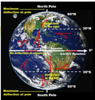
From the earth's surface to a gradient to the atmosphere, there is an experimental decrease on how wind efflux to a direction is distorted (see fig 1). To a greater height above earth features, there exist two principal forces which affect the horizontal movement of air. The Pressure Gradient Force (PGF) and the Coriolis force (CF). The PGF occur when air of two different densities and pressures (hot & cold air) meets or develops over an area. This generates to wind blowing as the two pressure differences endeavors to be same. This action can be demonstrated with the use of contours or isobars. The closer the isobar lines the higher the wind speed and the wider the isobar lines, the lesser the wind speed (see fig3). The CF occurs due to the turning effect of the earth globe and acts perpendicularly to the PGF (see fig 2). These two forces orientate the wind movement. (U.S Department of Transport - Federal Aviation Administration, 2016)
On the left panel, the contours/isobars are widely spaced apart, PGF is weak, and the wind speed is weak. On the right panel, the contours/isobars are more closely spaced, the PGF is stronger, and the wind speed is stronger. ( (U.S Department of Transport - Federal Aviation Administration, 2016) pp. 77
Coriolis force deflects moving objects to the right of their path in the Northern Hemisphere and to the left of their path in the Southern Hemisphere. Coriolis deflection is maximized at the poles and zero at the Equator (U.S Department of Transport - Federal Aviation Administration, 2016) pp 78
11
Figure 3: Isobar
It’s of no doubt from the meteorology study showing relevant, high wind velocities at progressive heights from the earth's surface. Exploiting this natural wind occurrence to produce clean energy, turbines are constructed on towers to propel so that the kinetic energy gain can be transformed to electrical energy. The higher the tower with a larger turbine propelling area, the higher the probability to be exposed to strong winds and likewise higher energy production. This is expressed in equation (1) derived from the law of energy transformation (C von der Haar, 2015).
Eqt. (1)………..
Where; P is the effective energy produce, A is the area of the rotor, V is the velocity of the wind and Cp is the power coefficient.
For this reason, wind turbines have grown by orders of magnitude, moving turbines into better wind regimes and using larger rotors to capture more energy.
Figure 4: Intower in rotor size and towers height from 1, 80 to the present (Wiser,Yang et Al.) The lines you see on this map are called isobars. Isobars show pressure on a map. H is cold air. L is hot air.
(http://www.ux1.eiu.edu/~cfjps/1400/FIG06_009.jpg)
12
Over heights of 85 – 90 m, steel towers are no longer competitive, partly due to the demands on the structures that considerably increase the overall cost of installation and due to the limitation in road transport for huge pieces. According to the literature consulted, hybrid towers constructed with prefabricated concrete and steel are especially relevant for current high-power turbines.
Nevertheless, in placements where the construction conditions are favorable, cast-in-place concrete towers provide a competitive alternative, adaptable to the most exacting structural demands and, through new designs and construction methods, more economically than their competitors.
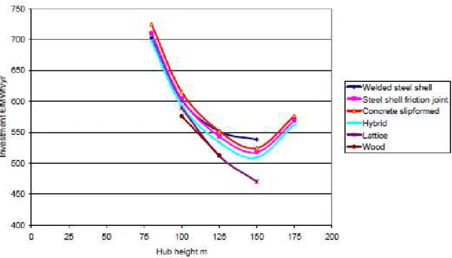
Figure 5: Summary of tower alternatives for 3 MW wind turbines
According to NREL, the plausible technologies to capture higher winds are the following: - Full-concrete, field-cast towers
- Hybrid factory-cast concrete and steel - Large diameter steel towers (LDST) - Lattice towers
- Soft-soft “can” tall towers - Spiral-welded towers
The following graphs show modelled data illustrating the difference in tower mass as hub height increases with soft-stiff towers and with soft-soft towers. Modeled data show that soft towers can capture a substantial portion of the mass (and perhaps cost) savings previously associated with the expanded base diameter.
At heights up to 100 m the cost of the different alternatives follow each other closely. At 125 m height the welded steel tower reveals a deviation towards higher relative cost. This tendency is even stronger at 150 m height, and it was not possible to design a welded steel tower for a hub height of 175 m. These tendencies are well explain by the
13
For example, for a hub height of 140 m, the tower mass in case of soft-soft towers varies from 400 t (unconstrained soft-soft) to 630 t (transportable soft-soft), while the tower mass in case of soft-stiff towers varies from 450 t (unconstrained soft-stiff) to 850 t (LDST soft-stiff). As it has been mentioned, transportable soft-stiff towers are not competitive over 90 m.
14
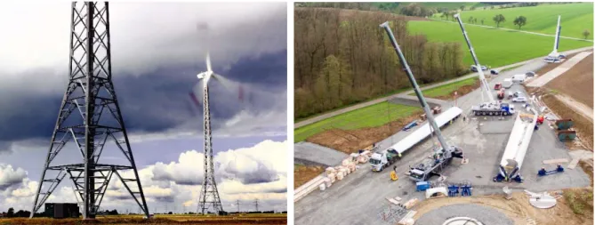
Figure 7: Lattice tower (left). LDST (right).
Figure 8: Spiral-welded towers
Innovation is very important to maintain the continued growth of wind energy the next years. However, there are a variety of tall tower technology concepts in play with no clear winner established. It is necessary to investigate and study different tower designs to achieve the goal of reaching higher winds.
1.2. AIMS & OBJECTIVES
Wind energy is maximally produced in an open windy, empty spaced area at considerable height. Exploiting this phenomenon, it becomes imperative to construct towers of great heights and mount nacelles and rotors to be propelled to higher wind velocity and optimize clean energy production. The main aim of this work is to test alternative hybrid wind turbine towers in different characteristic conditions to have a soft-soft tower at the end.
Analysing towers to extract soft-soft towers comes to solve high cost of soft-stiff and stiff-stiff towers. From the National Renewable Energy Laboratory (NREL), “Consistent with the modern history of wind power, turbine scale is anticipated to be a key attribute of cost reduction and market expansion” (Eric Lantz, 2017). Transportation and mass weight which has been the recent threats of high cost is one of the objectives of this research work.
15
EU 2020 goals has as a mission to cut down on energy consumption and CO2. Steel has been the main wind turbine tower material use for construction for decades. Its energy consuming circle for production and CO2 emission is quite alarming. Soft-soft Hybrid wind towers come to remedy this situation of alarming energy consumption and gas emission. Optimizing the use of concrete by substituting part of a steel tower becomes a partial solution to the reduction of energy consumption and CO2 emission. Being able to analyse towers with two different materials to function as a soft-soft tower solves part of the wind energy industry quest for better production.
The growth rate of wind energy has been so spontaneous and Europe is one of the leading continents to advocate for clean energy. Bigger blades and nacelle require an effective supporting structure. Targeting greater horizontal wind with greater speed, needs to move at higher altitude. Getting to the tall winds with a soft-soft hybrid tower, satisfies the aim of this research work.
1.3. WORK/RESEARCH METHODOLOGY AND LIMITATIONS
Modal analysis is one of the main methods used in the process of eigenfrequency evaluation for the wind turbine towers. It is obvious that every object has an internal frequency at which it naturally vibrates which is known as natural or resonant frequency. It is also the frequency where the object will permit a transfer of energy from one form to the other with minimum loss of energy. The response of a system when induced with an external energy or frequency provides an overview of the limit to the system (Harish, 2016)
Although modal analysis will be used to study the dynamic properties of the wind turbine when an external frequency is induced to the structure, it will move alongside with numerical simulations. This is a computer based mathematical calculation of a model of a physical system. Numerical simulations, study the behaviour of a system which has a complex mathematical model to provide analytical solutions. (herd, 2012).
For the construction of the in-situ reinforced concrete tower, it will be necessary to take into consideration that; “there are currently no design codes dealing exclusively with the design of concrete wind turbine towers” (W S van Zyyl, 2015). Nevertheless, the following design codes were used for the design processes:
- Eurocode 2; Design of concrete structures – Part 1-1: General rules and rules for buildings (EN 1992-1-1:2004/AC:2010)
- CEB-FIP Model Code 2010
- DNVGL-ST-0126 Support structures for wind turbines (2016) - BS 8110 - Structural use of concrete
The excitation of the tested hybrid wind towers will be evaluated through numerical simulations and model analysis only. This report is solely based on the result taken from the computation analysis. In case of weather changes the study of the towers will be limited to the provided information, although some safety coefficients will be of advantage in some vulnerable situations if need arises.
For a preliminary evaluation of a prototype wind tower, standards provided from the fabrication company for the nacelle, Steel tower fabrication and blades etc. will be strictly followed. The
16
fabrication industry final production characteristic notes will be the base of the characteristics to study the prototype tower.
Soft-Soft design towers have so far been studied, but the report for an executed prototype is still under development. Therefore, the physical existence with processes of execution is limited in this report.
1.4. SCOPE
Soft-Soft wind turbine towers have very low dynamic frequency vibration at its first vibration. This frequency value takes condition from other relevant factors that makes the tower resist or absorb some of the vibration.
A range of hybrid concrete-steel wind turbine towers will be analysed with various hypothesis which affects the vibration circumstances of the towers. These hypotheses range from the characteristic strength of the materials which the tower is made up of. The specific items to be tested here are the thicknesses of the concrete and steel section, the boundary condition, the superimposed loads from the nacelle and the blades.
Vibration tests will be run upon a battery of hybrid towers with different heights, but unique material characteristics and same imposed loads. The changes of the structural sizes of the towers will be followed carefully to see the differences it produces in its dynamic eigenfrequencies behaviour. During the testing of the various eigenfrequencies of the towers, the loads being considered will be the self-weight of the towers and the load of the nacelle. After obtaining the eigenfrequency result values for all the tested hybrid towers, the values which fall within the Soft-Soft design will be selected for other important analysis. Graphic results will demonstrate the possibilities of having soft-soft towers. An alternative graphic demonstration will also analyse the maximum heights concrete can be exploited to achieve soft-soft towers.
At the end of the study, a comparative analysis will be done to have a probable conclusion to achieve soft-soft hybrid wind turbine towers capable of extending to the strong winds in the near future. 1.5. STRUCTURE OF THIS REPORT
The first chapter consists of an introduction which gives an idea of how the wind is generated and what are the factors that influence the energy production. It includes the background and problem description, and the reasons for such problems which need attention in the future. Also, the aim, objectives, work/research methodology, scope and limitations are included.
Chapter 2 talks about the state of the art of wind turbine elements, including the supporting structure and the various types of wind turbines. The foundation description and soil investigation were most of the concentration the research took.
Chapter 3 states the basis of design, including hypothesis and inputs considered for the study. It explains the methodology for carrying out the research and calculations.
Results and proper analysis of the different alternatives studied are included in Chapter 4. Conclusion follows and the raw data with photo shopped in the appendixes.
17
2. STATE OF THE ART 2.1. INTRODUCTION
Wind towers are supporting structures which support and resist forces acting against the whole wind turbine structural system. A wind turbine is characterized by the location of its axis where the rotor rotates and the power output. The axis can be vertically or horizontally located. The axis of location gives different perceptions on how the supporting tower is designed. The power out-put can be estimated from the atmospheric conditions of the site and how wide the rotor diameter spans. (Bethany Kuhn, 2010). There exist two main designs of wind turbine, which are the horizontal and the vertical axis wind turbine. From (U.S Department of Transport - Federal Aviation Administration, 2016) report document, its well understood that, constant horizontal wind speed with limited share is available more at higher altitudes. From this, it can be deduced that, the horizontal axis wind tower is open more perpendicular to the horizontal wind profile at higher heights than the vertical axis wind turbine. Furthermore, more studies have been done for the horizontal axis wind turbine towers see fig. 4.
Figure 9: Location of Horizontal (HAWT) & Vertical (VAWT) Axis Wind Turbine
Regardless of the position of the axis of rotation, what is paramount in this study report is the tower’s capability to resist all the physical and dynamic loads which it bears within the specific characteristic of soft-soft domain. Characterizing a tower as Soft-Soft is through the influence of its dynamic characteristic performance outcome through vibration. The vibrational conduct of a wind turbine can be monitored just when the solidness and mass parameters of every one of its parts are deliberately coordinated (Milan Veljkovic, 2015).
18
Figure 11: Cthe rotor speedgram relating rotor speed and eigenfrequencies of towers (Milan Veljkovic, 2015) Blade Hub Nacelle Tower Foundation
19
What is important and paramount in a HAWT design which is the focus of this report is the way it vibrates and the tower’s response to the vibration under operation. Evaluating the vibrations in terms of frequencies, clearly distinguishes how the tower can be classified within (Soft-Soft, Soft-Stiff & Stiff-Stiff). The frequencies are termed natural frequencies and when plotted on a graph with the Rotor angular speed (1P) which is considered as the first frequency of excitation and the vibrations emanating from the blades under revolution (2P or 3P…) see fig 2.3.
To be vivid enough about the excitation frequency of the rotor and the blades, the rotor frequency is being equated to the excitation frequency produce by one blade during a revolution and identified as (1P) considering that the wind turbine has just one blade. Taking into consideration more than one blade e.g 2 or 3blades, the excitation frequency of the blade is either 2P or 3P depending on the number of blades the tower possesses. It’s also good to note that, the more the blades, the higher the harmonic frequencies (Milan Veljkovic, 2015)
“The tower’s first bending eigenfrequency or natural frequency should not coincide with the critical, exciting forces” (Milan Veljkovic, 2015) .This is the risk of admitting resonance. It is also not advisable to design using the exact rotor and blade frequencies. A safety coefficient or safe distance of 0,25 P from the dominant frequency of excitation and of 0,15 P to 0,20 P from the less critical ones is a good guide value (Milan Veljkovic, 2015). Other experts like (W S van Zyyl, 2015) presented gave a representative diagram as shown in fig 2.4. The excitation frequencies are either used as 1.1P for the rotor and 2.7P for the blades. These positions of frequencies, does not coincide with the exact excitation frequency values.
Figure 12: Excitation frequencies (W S van Zyyl, 2015)
To give the satisfactory dynamic behaviour and control of resonance of a soft-soft tower, the natural frequency should be gotten taking into consideration the imposed load by the nacelle, the stiffness of the foundation and the soil structure interaction (Boundary Condition). The Minimum rotational stiffness of the foundation implies a minimum subgrade reaction modulus that must be checked using adequate site tests like Bore-hole or seismic refraction tests. (Milan Veljkovic, 2015) The seismic refraction test is more advance to carry out such soil test due to its ability to provide wider information about the soil strata than the other tests. If all the necessary means put in place to avoid
20
resonance is not being achieved, other possible additional measures to control vibration during
operation must be implemented. A mechanical system like “tuned mass dampers” could be useful for such a project.
2.2. NACELLE
A nacelle of a wind turbine is that portion of the wind turbine, which house the mechanical energy conversion and generating equipment. This includes brake assembly, drive train, gearbox and the generator.
Figure 13: Cross section of a nacelle
(http://www.daviddarling.info/images2/wind_turbine_nacelle.jpg)
Fig 2.10, shows a simple demonstration how a nacelle work and its constituents. There exist three main units which are necessary in the nacelle for energy production. You have the low-speed shaft which is being rotated by the help of the blade rotation caused by the wind. Attached to it is a bigger gear tooth, which connects its self to a smaller gear tooth on a high-speed shaft and links to the generator where the mechanical energy from the high speed-shaft is converted to electrical energy. There exist different forms and types of nacelles and the manufacturer classify nacelles according to the sizes of the blades corresponding to the expected energy produced. The casing of a nacelle is of fiberglass structure due to the light weight it offers.
2.3. HUB
A wind turbine hub is that connecting mechanism of a wind turbine, which the blades are being assembled on. The turbine rotor and hub revolve at a rate of 10 to 25 revolutions per minute (rpm) depending on the turbine size and design either in a constant or variable speed. The hub is attached to the low-speed shaft which connects to the high-speed shat with the use of the gear teeth and moves into the generator. (International Renewable Energy Agency (IRENA), 2012)
21 Figure 14: Hub (https://upload.wikimedia.org/wikipedia/commons/thumb/6/65/Connecting_Hub_to_Turbine_Towe r_No_11_-_geograph.org.uk_-_787410.jpg/220px-Connecting_Hub_to_Turbine_Tower_No_11_-_geograph.org.uk_-_787410.jpg) 2.4. BLADES
Blades are the main energy starter to develop wind energy. As the wind blow on it surfaces, it creates a tendency to rotate. Blades are of different numbers on a wind turbine, but recent development has adopted a system of three blades. “The blades are manufactured from fiberglass-reinforced polyester or epoxy resin. New materials such as carbon fibre are being introduced to provide higher strength -to -weight ratio needed for the ever-larger wind turbine blades being developed” (International Renewable Energy Agency (IRENA), 2012). Wind turbine blades are also possible to be manufactured using laminated wood. The disadvantage of this is the limited size it will enhance. (International Renewable Energy Agency (IRENA), 2012).
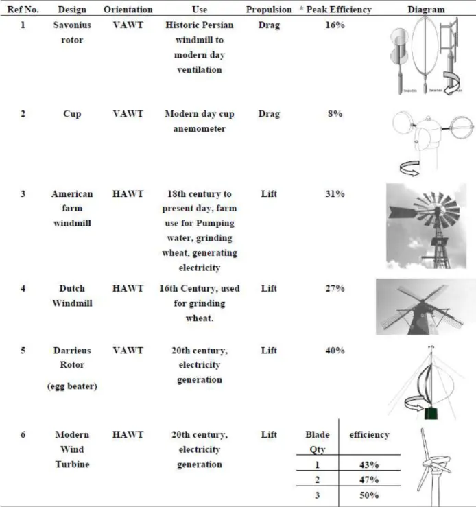
Wind turbine blades have some development experience for the past centuries. This developer keeps advancing with a bottom line on how much the mechanical system can maximally assist in clean energy production. Wind turbine blades do exist in two types. The vertical axis wind turbine (VAWT) blades which functions under the Drag force system of propulsion and the horizontal axis wind turbine (HAWT) blades which acts under the lift force system of propulsion. ‘Darrieus’ in the 20th century modified the design of VAWT blades to be propulsion with the lift system and had a reasonable result though not as efficient comparing with the 3 blades HAWT.
More concentration in the wind energy industry is being centred on the HAWT blades due to the high energy efficiency it could produce and are very sensitive to changes in blade profile and design. The tip speed ratio is the fundamental advantage the HAWT blades do possess over the VAWT blades with respect to aerodynamics.
The tip speed ratio is defined as the relationship between rotor blade velocity and relative wind velocity [Equation (2)] is the foremost design parameter around which all other optimum rotor dimensions are calculated:
22
On table 1, a display of evolutional design of blades by their authors and the efficiency of blades to recent days.
Table 1: Modern and historical rotor designs. (Crossley, 2012)
23 2.5. WIND TURBINE TOWERS
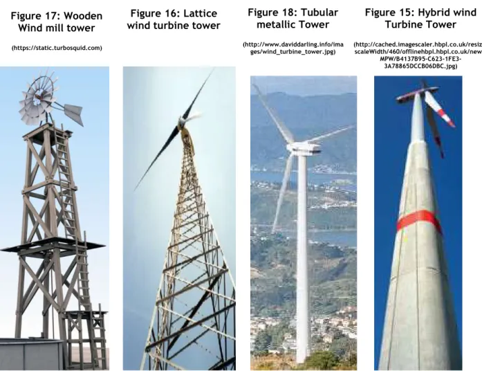
A wind turbine tower is the vertical supporting element which gives an elevation to the Nacelle and the blades into the less share horizontal wind profile above the human existing level. This vertical structure can be made up of metal sheets, metal frame structures or wood. Due to the complex behaviour of its sustainability to resist structural failure, a lot of studies have been done on the structural element as to advance its mechanical fabrication to suit cost and gain higher heights. For these reasons, other ideas are extinguished from present days due to, inability to access the strong horizontal wind profile and boast its structural sustainability in a relevant cost.
Wind turbine towers exist in the above structures as shown from fig2.7 to fig 2.9. With the main ambition to advance into the horizon strong wind profile. With the high demand of wind energy as the study shows, more researches, ideas are being put together to increase the production of wind energy. As the ability of acquiring horizontal wind profile increases in height from the earth's surface, and the blades increase in size, conjoin with the mass increase of the nacelle for higher energy production, the supporting structure becomes complex.
To reiterate for a proper follow up, and understanding, there are three main design ways on how a wind turbine tower can be characterized in respect to its structural stability irrespective of the kind of materials. The first design type is that which it’s fundamental frequency (f0) is higher than the 3P
Figure 17: Wooden Wind mill tower (https://static.turbosquid.com)
Figure 16: Lattice wind turbine tower
Figure 18: Tubular metallic Tower (http://www.daviddarling.info/ima
ges/wind_turbine_tower.jpg)
Figure 15: Hybrid wind Turbine Tower (http://cached.imagescaler.hbpl.co.uk/resize/
scaleWidth/460/offlinehbpl.hbpl.co.uk/news/
24
frequency interval; that is, the blade passing frequency (fb). This type of a tower is called a stiff-stiff structure. The second option is design such that its fundamental frequency is between 1P an 3P frequency; the fundamental frequency of the tower f0 should be between the rotor frequency (fR) and the blade frequency (fb). It is known as a Soft-Stiff tower. The third option is that which its design fundamental frequency below the 1P frequency which is known as a soft-soft structure. This concept is illustrated in Figure 2.4 (W S van Zyyl, 2015).
2.5.1. Hybrid wind turbine towers
To understand this proposition better some fundamental hypothesis are exhibited for proper basic understanding and functional properties of a hybrid wind turbine. This is to define and give a vivid explanation on how some of the parts work and how it affects the supporting structure of a wind turbine.
Figure 19: Hybrid wind turbine tower (http://www.nordex-online.com/uploads/pics/120_Meter_01.jpg)
2.5.2. Modal analysis of wind turbine towers
Hybrid wind turbine towers are one of the most complex structures to sustain its self at very high altitude. In such a circumstance, Modal analysis becomes the most important studies that are considered to solve such complex structures. Modal analysis deal specifically on how a structure vibrates with the application of external forces. Since every object vibrates to a certain frequency called the natural frequency, it will be wise enough to computerize the natural frequencies and mode shapes of wind turbine supporting structure components. This assessment gives a vivid, dynamic understanding between the resistant relationship in the various parts or components of a wind turbine. It permits in the process of sizing, wind turbine components during the manufacturing and
Concrete tower section
Steel tower section
Hybrid wind Turbine Tower Blade Nacelle Hub Foundation
25
design processes. When a structure vibrates due to an external influence or energy transformation, the frequencies that it produces during vibration is known as natural frequencies. During these vibrations, the structure produces different deformed shapes as the vibration moves within the structure. The deformed shape at each frequency of vibration is called the “Mode of vibration”. The deformed shapes under vibration are relative to their structural property, material components and each mode shape are associated to a specific natural frequency band. Dealing with a hybrid concrete turbine tower, different variation of structural properties would be reflected to a variation of a band which the structure vibrates but the mode shapes will remain the same. But when the boundary conditions do change, characteristic mode shape and natural frequencies would change. (Luca Pagano, 2017). More about modal analysis will be seen in the upcoming chapters because it's the unique methodology applied here to acquire alternative design for a soft-soft tower from the other methods.
Figure 20: Modal analysis of a concrete tower (Alexandros Iliopoulos, 2016)
2.5.3. Materials and geometry commonly used for wind turbine towers
There exist a wide range of materials used in wind turbine tower construction. These materials are adopted by the designers on the relative cost and purpose it enhances to serve. In a relative size, condition, substantial differences between small and large machines influences the choice of material to be adopted for the supporting structure. Materials used in constructing a wind turbine tower could be adopted with a forecast of projected changes in designs that will accommodate the introduction of new material technologies and manufacturing methods. The estimated materials use in small and large turbines is shown in Table 2. To summarize it all, the material used is weighted by the estimated market share of the various manufacturers and machine types. (Dan Ancona, 2001)
26
Table 2: Percentage of Materials Used in Current Wind Turbine Component (Dan Ancona, 2001)
Notes:
1. Small turbines with rated power less than 100 kW- (listed in italics where different) 2. Assumes nacelle is 1/3 gearbox, 1/3 generator and 1/3 frame & machinery
3. Approximately half of the small turbine market (measured in MW) is direct drive with no gearbox
4. Rotor blades are either glass reinforced plastic, wood-epoxy or injection moulded plastic with carbon fibres.
Tubular steel towers have been for long used for wind energy supporting structural system. There vary in quality and sizes for economic and structural sustainable reasons. The choice of a tubular steel tower rests on the decision of the turbine manufacturer. Therefore the operating system of the rotor’s frequency and the size of the nacelle jeopardize the quality and size of the tubular steel tower. It will be necessary to reiterate here that wind energy is a fast-growing renewable energy technology and the most commercially developed. The wind turbines supporting structure are of mostly conical shapes fabricated with metal sheets ranging from 8- 40mm thick. Modular wind turbine tower can move up to a reasonable height of about 80m but this will hugely depend on the size of its natural frequency to the rotor and blade passing frequencies. The larger the tower’s diameter, the more transportation challenges it will witness. This can be mitigated by fabricating the tower into panels but the cost of transportation and the weight is still an impediment see fig. 17 (a)(b).
The fabrication is done and some constructed without any internal stiffeners which becomes vulnerable to adapt in bigger scale wind turbine supporting structures. It will be made known later in this study the limitations steel tower possesses as to advance to the recent high demand of wind energy. (Ran, 2014)
The International Electrotechnical Commission (IEC) sets international standards for the wind speeds for which, each wind class must withstand as seen in the table 3 below. It shows that; larger
27
rotors are required to capture the same amount of energy as a similar turbine at a Class II site thereby warranting the size of the supporting system.
Table 3: International Electrotechnical Commission (IEC) (https://www.lmwindpower.com)
Figure 21: (a) Novel modular tower (b) Conventional tubular tower (Ran, 2014)
Figure 22: Northstar modular tower cross section (left). Modular curved panel (right) (Ran, 2014)
2.6. FOUNDATION
For any structure to sustain its own weight combining with other imposed loads, highly depends on its foundation. The foundation is of a kind that suits the geological characteristics of the soil strata of the given area of construction. This is to say that; foundations highly depend on their soil grades. Pertaining to such complex structure as wind turbine is a concern, critical attention must be paid to such a circumstance. Wind turbine foundations become so critical for soil inspection due to the high
28
ability of moment or turning effects it subject to the foundation structure. The forces acting on the foundation results from the vertical and the horizontal direction.
The vertical direction mostly resonates from the chiefly dead load of the tower, the nacelle, and the rotor blades. These loads are considered with a negative sign during the calculation of the structural behaviour of the tower due to its sense of action. However, wind also adds to the vertical components subjected to the tower. The wind is mostly considered a horizontal force acting against the stability of the tower. Due to the force that it exerts on the blades and the structural body of the tower, it gives a high prevalence of a push or a pull which has a vertical acting force component.
To fight against all these forces as to obtain an equilibrium or a stable reacting situation, some safety preferences should be put in place. The type of foundation given to a wind turbine must be able to sustain quasi estimated loads. Environmental factors that may deteriorate the strength like earthquakes, erosion or sedimentation or any form of chemical reaction in a long-term duration should be prevented maximumly. In the design phase, foundations for towers are considered as a link to the vertical structure. This link is mostly design under a boundary condition of being rigid, although it does not occur like that under operation. It saves as a safety factor under designing process of the foundation. Wind tower foundations can be analysed using the finite element model method (FEM). This method is implemented to the foundation to relate the eigenfrequency of the tower, which will cause a seismic action to the foundation. The eigenmodes gotten from the seismic actions from the tower are just same represented like that of the tower (Friedrich Pfeiffer, 2011). Its of construction, technical principles that; loads on a supporting structure should be wholly and laterally transmitted to the foundation. So, the number of eigenmodes which are considered in the foundation design, analysis must guarantee that the percentage of excited mass is at least 85% (Friedrich Pfeiffer, 2011).
Wind turbine tower has three characteristic design criteria which in either way guarantee its stability. This is regardless of the type of materials used in its construction or the position where it will be constructed. These criteria are Soft-Soft, Stiff–Soft, Stiff–Stiff. They are established in respect to the EIGENFREQUENCY (ie natural resonant frequency) of the tower. From the characteristic nature for which a tower can be described, it has a unique solution for its design sustainability. Therefore, there exist three design solutions for a wind turbine tower depending on the ratio between the fundamental frequency f0 and the Rotor frequency fR and the blade passing frequency
=Nb . fR . For a soft-soft design f0<fR and for Soft-Stiff, fR < f0< fb and lastly Stiff-Stiff; fb< f0 (Kuhn,
1997) Where;
fb= Frequency of the blades
fR= Frequency of the rotor
f0 = Natural frequency
From the above criteria on how towers are classified by (Kuhn, 1997), there is a clear interpretation from (Friedrich Pfeiffer, 2011) why he adopted seismic FEM to design wind turbine tower foundations. (Friedrich Pfeiffer, 2011) adopted the wind turbine tower foundation designing backed by the German code of practice DIBt. The preliminary design evaluation condition states that;
29
Where fR2 is the second frequency of the rotor, fT1 and fT2 eigenfrequency of the tower.
A foundation as a structural element, transmit loads to the subsoil. Its function’s optimally when the soil in direct contact has a good bearing density to evenly distribute the transferred loads to the earth's crust. Excavating to such soil bearing capacity without some investigation, can be misleading in respect of such giant projects. Sounding techniques are always employed to the site to adequately have a preview of the soil strata. Some of these soundings still fail to give the designer adequate information for proper designing. Seismic refraction is the most developed technology for soil strata investigation. It provides more information than the sounding method. The multifaceted results it provides enable the foundation designer to take comfortable decisions for the stability of the structure. Seismic refraction is capable to provide multiple result as numerated below; (GEOMETRICS, 2017)
- Estimating rippability prior to excavation - Mapping depth to bedrock/bedrock topography - Mapping depth to ground water
- Measuring the thickness of the weathering zone
- Calculation of elastic moduli/assessment of rock quality - Mapping thickness of landslides
- Identification and mapping of faults
With such fantastic information seismic refraction test can provide, it offers easement to decide a choice for the foundation structure. It also gives a privilege on how excavation activity can be organized according to Bieniawski interpretation graph.
30
Bieniawski (1976) published the details of a rock mass classification called the Geomechanics Classification or the Rock Mass Rating (RMR) system. This research has undergone some changes to the rating assigned to different parameters. The 1989 version is the most updated.
31
3. BASIS OF DESIGN AND METHODOLOGY 3.1. BASIS OF DESIGN
3.1.1. Hybrid concrete tower
The advantage of choosing a hybrid tower is that the concrete tube is produced on site, thus dispensing with the need for overland transportation, while the standard tower sections can be carried on conventional vehicles, taking advantage of the full development of steel tower industry. At the same time, it shall be guaranteed that the overall system has an adequate resonance frequency by adjusting different geometry parameters.
3.1.2. Concrete tower geometry
One of the main factors of a designer designing complex structures like wind tower support is the relevant cost it entails. As a supporting tower can represent as much as 65% of the weight of the turbine, therefore it is paramount considering the affordability of the tower construction materials. The introduction of pre-stressed concrete in megawatt wind turbine tower design has been alarming. Due to the mechanical, structural properties it possesses, it alters the behaviour of an upright tower by increasing it compressive nature. This is noticeably used in greater amounts in European turbines, especially in offshore or near-shore applications. Using Concrete in tower construction, has the tendency to lower the cost, but may involve nearly as much steel in the reinforcing bars as a conventional steel tower. (Dan Ancona, 2001).
Although how advantageous the pre-stressed concrete and ordinary reinforced can offer as resistant to a tower, researchers still have different ways on how they see its implementation. The relative base of their facts is still to cut down costs and a probability to move higher heights. Also, they hold on different advantages on the shapes a tower could best perform in resistance and during the construction and installation processes. To advance with this report, it was necessary to consider the researcher’s ideas and adopt a unique type which will proceed in this report. The geometry of a tower plays a great role in their structural stability. Most wind turbine tower's steel/concrete are of spherical shapes. Taken from (F. Ballester, 2016), he studied pre-stressed concrete reinforced tower with a Square to Circle (S2C) shape-like as he called it the geometry consists of a square section with rounded corners at the base of the tower and a circular section at the top of the tower see (fi. 3.2). The transition between both sections is achieved by reducing the straight part of the formwork and keeping a constant curvature for the corners. The tower is divided in two parts;
1. The first part which begins from ground level 0.00m to 196 m. It’s being constructed with in-situ reinforced concrete with a constant wall thickness value of 0.4 m. The last two concrete meters have a thickness value of 0.8 m. The aim of this preliminary design of the tower top is to allow the installation of the posttensioning anchorages and the steel connection piece. 2. Steel connection piece of 2 m, from 196 to 198 m.
This tower was studied considering two types of in-situ grade concrete (C35/45 & 40/50). The reason for this dual concrete grade was to see how concrete grade influences the natural frequency and the fatigue of the tower. From (F. Ballester, 2016), “The main advantage of the S2C tower geometry apart from being cost effective and relatively dynamic is that; it allows the use of a climbing
32
formwork system for its construction. This type of construction system is commonly used on vertical walls and high concrete structures, since it allows the repetitive use of the same formwork for identical or very similar sections.” From his study, its best to adopt the system of producing geometries of wind turbine towers due to the accessibility of higher heights using the climbing formwork system.
Figure 24: S2C Mould shapes. (F. Ballester, 2016)
Figure 25: Climbing formwork elements. (F. Ballester, 2016)
From a vivid understanding from (F. Ballester, 2016) about the advantage of the S2C, (Ran, 2014) also confirm a circular structure as the best design for a wind-turbine tower because it can bear the same load from each direction. But (Ran, 2014) contradicted that; the construction of a concrete wind-turbine tower requires circular steel moulds which are expensive and cannot be reused for other wind farms because different wind farms use different models of steel moulds. (Ran, 2014) proceeded by substituting a circular cross section with a regular polygon, the number of sides of which is determined according to two principles.
33
1. The differences in the natural periods in any direction of the wind-turbine tower are within 1%.
2. The differences in the maximum stress of the cross section in any direction under the same load are within 5%. For (Ran, 2014) the number of regular polygons varies from 4 to 12 and the basic parameters for two reference towers are listed in Table 2.
Table 4: Parameters of concrete wind turbines (Ran, 2014)
Figure 26: Design Diagram of a Pre-stress 8-sided polygon in-situ concrete wind tower (Ran, 2014)
Comparing both methods used by (F. Ballester, 2016) and (Ran, 2014) the most economical idea in executing and less time consuming, (F. Ballester, 2016) has an upper advantage. With the smooth interior circular shape of (F. Ballester, 2016), creating a mould will take less time and lesser panels than that of (Ran, 2014).
It has been shown that a soft-stiff structure is more economical than a stiff-Stiff for wind turbine towers (W S van Zyyl, 2015). It will be of need to remind here that, it is the value of the natural frequency of a tower to satisfied if it is a soft-soft, soft-stiff, stiff-stiff tower. It is not possible to calculate the exact fundamental frequency of a structure at the study stage, because there are various factors and unconscious impacts that may influence the frequency. Due to this uncertainty, the frequency of the tower is kept out of 10% of the 1P and 3P frequency intervals (W S van Zyyl, 2015) The frequency between the 1.1P and 2.7P frequencies, is defined as the working frequency for a soft-stiff tower design.
34
It is estimated that, by assuming the foundation to be fully fixed, the error in the fundamental frequency of the tower can be up to 20% (W S van Zyyl, 2015) . Wind turbine guidelines generally propose that elastic springs are used to simulate the soil stiffness. (W S van Zyyl, 2015) made us to understand that; the height of the tower and the weight of the turbine are set by the turbine manufacturer; therefore, designers only have limited options for shifting the eigenfrequencies of the structure into the permissible range defined by the Campbell diagram. Today, most simulation software can determine the eigenfrequencies of a wind turbine with high reliability. Alternative calculations based on energy methods also yield good results.
Though both researchers have different approaches in the way they embrace concrete wind turbine towers, they had almost same reason why there went further to research on concrete towers rather than steel towers. They both accepted the fact that transportation of metallic wind tower panels of more than 4m in diameter limits the ability to grow bigger the steel wind turbine. Also, as the wind turbine grows bigger in height and in size, there is an increase of complexity with the structural behaviour of the steel towers in respect to their stiffness. There is also a less possibility of fixing climbing formwork on tapered steel towers. For economic reasons, concrete towers are cheaper than steel towers. (Ran, 2014) further indicated that precast concrete solutions are potentially 30% less expensive than steel towers for tower heights of 70–120m.
Although concrete is being characterized in various forms like the strength which deals with the constituents of the concrete mix and how long it’s been cured and cement type and dosage. It’s still have been a competitive material choice for designing towers, including tall chimneys, poles and bridges. Compared with a steel tower, a concrete tower has advantages such as more flexibility in construction and design, less maintenance requirements, better dynamic response and better transportation possibilities. (Ran, 2014) concluded that prestressed, concrete tower has greater durability with longer fatigue life and the tower service life varies between 40 and 60 years. It's therefore for these reasons that multi-megawatt concrete wind-turbine towers are being deployed around the world.
3.1.3. Tower main characteristics
The tower will compose of a proportionate height of pre-stressed concrete and other of modular steel. The shape adopted for the concrete section is that of (F. Ballester, 2016) S2C due to its ability to be constructed progressively with the climbing formwork. The specifications are as follows. Case 1
The aim of Case 1 is to study the influence of concrete thickness, base diameter and total height on soft-soft design while keeping the steel tower part constant. An eigenfrequency analysis is carried out on the tower by increasing the height of the concrete section and its base diameter accordingly. These are the main inputs:
- Constant steel section of 87 m and thickness of 0.04 m.
- Variable concrete section from 58 m to 98 m, which means a hub height varying from 140 m to 180 m.
- Variable concrete thickness considering three options: 0.35 m, 0.4 m and 0.45 m. - Variable concrete base diameter from 6 m to 11 m.
35
The following table summarizes the 108 alternatives to be analysed in this first study.
Table 5: Case 1 – Alternatives studied
No. e (m) H (m) Dc,base (m) No. e (m) H (m) Dc,base (m) No. e (m) H (m) Dc,base (m) 1 0.35 140 6 37 0.4 140 6 73 0.45 140 6 2 7 38 7 74 7 3 8 39 8 75 8 4 9 40 9 76 9 5 10 41 10 77 10 6 11 42 11 78 11 7 150 6 43 150 6 79 150 6 8 7 44 7 80 7 9 8 45 8 81 8 10 9 46 9 82 9 11 10 47 10 83 10 12 11 48 11 84 11 13 160 6 49 160 6 85 160 6 14 7 50 7 86 7 15 8 51 8 87 8 16 9 52 9 88 9 17 10 53 10 89 10 18 11 54 11 90 11 19 165 6 55 165 6 91 165 6 20 7 56 7 92 7 21 8 57 8 93 8 22 9 58 9 94 9 23 10 59 10 95 10 24 11 60 11 96 11 25 170 6 61 170 6 97 170 6 26 7 62 7 98 7 27 8 63 8 99 8 28 9 64 9 100 9 29 10 65 10 101 10 30 11 66 11 102 11 31 180 6 67 180 6 103 180 6 32 7 68 7 104 7 33 8 69 8 105 8 34 9 70 9 106 9 35 10 71 10 107 10 36 11 72 11 108 11
36
Figure 27: Hybrid wind turbine of 140m hub height (Aweh Autodesk 2017)
Case 2
From the results obtained in Case 1, a second analysis is carried out by selecting a constant concrete thickness and a base diameter. In this case, the objective is to study the different alternatives for a soft-soft design by modifying both concrete and steel sections. These are the main inputs:
- Variable steel section from 87 m to 112 m. - Constant steel thickness of 0.04 m.
- Variable concrete section from 26 m to 111 m, which means a hub height varying from 140 m to 200 m.
- Constant concrete thickness of 0.38 m.
37
Table 6: Case 2 – Alternatives studied
No. H (m) hsteel (m) hconcrete (m) Ds,base (m) Dc,top (m) Dc,base (m) 1 140 87 51 4.08 6.10 7.10 2 92 46 4.12 6.10 7.10 3 97 41 4.16 6.20 7.20 4 102 36 4.20 6.20 7.20 5 107 31 4.24 6.20 7.20 6 112 26 4.27 6.30 7.30 7 150 87 61 4.08 6.10 7.10 8 92 56 4.12 6.10 7.10 9 97 51 4.16 6.20 7.20 10 102 46 4.20 6.20 7.20 11 107 41 4.24 6.20 7.20 12 112 36 4.27 6.30 7.30 13 117 31 4.31 6.30 7.30 14 122 26 4.35 6.40 7.40 15 160 87 71 4.08 6.10 7.10 16 92 66 4.12 6.10 7.10 17 97 61 4.16 6.20 7.20 18 102 56 4.20 6.20 7.20 19 107 51 4.24 6.20 7.20 20 112 46 4.27 6.30 7.30 21 117 41 4.31 6.30 7.30 22 122 36 4.35 6.40 7.40 23 127 31 4.39 6.40 7.40 24 132 26 4.43 6.40 7.40 25 165 87 76 4.08 6.10 7.10 26 92 71 4.12 6.10 7.10 27 97 66 4.16 6.20 7.20 28 102 61 4.20 6.20 7.20 29 107 56 4.24 6.20 7.20 30 112 51 4.27 6.30 7.30 31 117 46 4.31 6.30 7.30 32 122 41 4.35 6.40 7.40 33 127 36 4.39 6.40 7.40 34 132 31 4.43 6.40 7.40 35 137 26 4.47 6.50 7.50
38
No. H (m) hsteel (m) hconcrete (m) Ds,base (m) Dc,top (m) Dc,base (m) 36 170 87 81 4.08 6.10 7.10 37 92 76 4.12 6.10 7.10 38 97 71 4.16 6.20 7.20 39 102 66 4.20 6.20 7.20 40 107 61 4.24 6.20 7.20 41 112 56 4.27 6.30 7.30 42 117 51 4.31 6.30 7.30 43 122 46 4.35 6.40 7.40 44 127 41 4.39 6.40 7.40 45 132 36 4.43 6.40 7.40 46 137 31 4.47 6.50 7.50 47 142 26 4.51 6.50 7.50 48 180 87 91 4.08 6.10 7.10 49 92 86 4.12 6.10 7.10 50 97 81 4.16 6.20 7.20 51 102 76 4.20 6.20 7.20 52 107 71 4.24 6.20 7.20 53 112 66 4.27 6.30 7.30 54 117 61 4.31 6.30 7.30 55 122 56 4.35 6.40 7.40 56 127 51 4.39 6.40 7.40 57 132 46 4.43 6.40 7.40 58 137 41 4.47 6.50 7.50 59 142 36 4.51 6.50 7.50 60 147 31 4.55 6.60 7.60 61 152 26 4.59 6.60 7.60 62 200 87 111 4.08 6.10 7.10 63 92 106 4.12 6.10 7.10 64 97 101 4.16 6.20 7.20 65 102 96 4.20 6.20 7.20 66 107 91 4.24 6.20 7.20 67 112 86 4.27 6.30 7.30 68 117 81 4.31 6.30 7.30 69 122 76 4.35 6.40 7.40 70 127 71 4.39 6.40 7.40 71 132 66 4.43 6.40 7.40 72 137 61 4.47 6.50 7.50 73 142 56 4.51 6.50 7.50 74 147 51 4.55 6.60 7.60
39
No. H (m) hsteel (m) hconcrete (m) Ds,base (m) Dc,top (m) Dc,base (m) 75 200 152 46 4.59 6.60 7.60 76 157 41 4.63 6.60 7.60 77 162 36 4.66 6.70 7.70 78 167 31 4.70 6.70 7.70 79 172 26 4.74 6.80 7.80
3.1.4. Rotor and nacelle data
The following masses and centres of gravity are considered for the calculations: - Rotor weight: 82000 kg
- COG rotor: 2 m
- Nacelle weight: 125000 kg - COG nacelle: 1.2 m
3.2. APPLICATION OF MODAL ANALYSIS FOR SOFT-SOFT DESIGN
Modal analysis to be reiterated; is the ability to evaluate how a body vibrates. From the conservation of the law of conservation of energy which states that “Energy can neither be created nor destroyed; rather, it can be transformed from one form to another”. Wind turbine towers are greatly exposed to this phenomenon which gives a high rise of vibration or excitation. These loads come from various transformations and directly affect the structural stability of the tower. Knowing and examining these loads gives a better chance to understand the simulation performances of a wind turbine tower. From the simulation performances, the wind turbine tower can be adapted to different characteristics of loads, material resistances as to have a different physical behaviour.
Wind turbine loads are characterized at the ultimate and service limit states known as the extreme and the operating loads. This is calculated with the total dynamic load simulations. In these simulations; The tower, the turbine, the wind gusts that is; a sudden increase of wind speed, the starting of the wind turbine, the operation and stopping procedures of the wind turbine, and the dynamic performance of the whole system made up of the kind of foundation which creates a boundary condition, are highly to be considered. The stiffness of the tower as already mentioned has a direct impact on the resulting internal forces. To limit dynamic mishaps, avoid dynamic amplification of equal magnitude, the eigenfrequencies of the structure should not be within the range of the excitation frequencies of the turbine. (C von der Haar, 2015)
Knowing all the factors which occur on a wind turbine tower, it can be easily simulated and processed in a computer software “MIDAS Civil”. Understanding modal analysis and various nomenclatures, designers can easily understand the natural vibration frequencies of a system to ensure that they are not the same as excitation frequencies and thereby ensuring safety in their designs. From the results of the eigenfrequency and the excitation frequencies plotted on a Campbell diagram. From the complex evaluation, analysis from “MIDAS Civil” software, it will be advisable to have a vivid knowledge and description about the software before presenting the results and the entered data of the sample towers.
40 3.3. MIDAS CIVIL SOFTWARE
MIDAS Civil is an engineering graphic software with diverse functions to evaluate the physical reactions of functional structural units under various types of load condition. With the ambiguous functions MIDAS Civil software do perform, a summarized description will be described here. This software solves the complex mathematical evaluations to determine tower’s eigenfrequencies under various imposed loads through simulation.
3.4. SIMULATION
Simulation is the ability to create tentative objects to represent a real object using computerized programs which could be easier to perform a modal analysis. In another word, it’s the ability to convert physical objects theoretically by designing in Computer Aided Design (CAD) programs to guarantee a theoretical study analyses for a proper physical execution output. Simulation is one of the most used scientific methods of learning which is by doing it in a hypothetical world through modelling the sample of what is to be studied to see how it operates. This system of science, brings a clearer view to young learners and inexperienced persons in an industry with a clear view of what they're subject of operation is all about. Some physical objects become so complex to understand its physical existent under natural actions like planes, dealing with aerodynamics behaviours and wind turbine towers dealing with wind pressure and excitation frequencies under modal analysis. To best understand its dynamisms, it’s easier to evaluate when the structure is being simulated and subjected to the hypothetical forces for a better theoretical performance analysis. Describing this performance analysis using MIDAS CIVIL software, it will be subdivided into five processes to have the resulting performance of a simulated wind turbine tower eigenfrequency.
3.5. PROCEDURE OF SIMULATING A MODEL AND MODAL ANALYSIS PERFORMANCE Before creating an interface, your computer must have been installed with the licensed MIDAS CIVIL Software. The interface is an interactive page with tools and other dispositions. The interface can be subdivided into four parts which are; The standard Tool bar, The Tree Menu, The message Window and the working space or the displayed area. See Figure 28.
These procedures could be divided as follows: - Creating an interface
- Creating materials and sections - Creating a structural model
- Assigning loads and boundary conditions - Analysing and verifying results
3.5.1. Creating an interface
Before creating an interface, your computer must have been installed with the licensed MIDAS CIVIL Software. The interface is an interactive page with tools and other dispositions. The interface can be subdivided into four parts which are; The standard Tool bar, The Tree Menu, The message Window and the working space or the displayed area. See Figure 28.
At the top right end of the standard toolbar (STB) can open a new project or interface page. Other attributes from the STB can be used to formalize or set the workspace. This will depend on the type
41
of structure to be worked upon. The grid icon from the STB should be activated as to know the coordinates at which the structure is situated. Other types of grids do exist, but that to be used here are “Point Grids”.
Figure 28: MIDAS CIVIL Interface (MIDAS 2016)
Grids should be set within some distances, but that should be done after the designer must have confirmed the SI Units he will be using. To change the units, it’s found at the bottom right of the interface Midas civil page below the message window dialogue box. To set the grid distances, click on “Structure” on the STB. Click to grids and in the drop-down menu, select “Define point grid”. To define the points, it simply means input the respective changes the X-axis makes with the Y-axes. Here the Z-axes is needless because it’s just a platform without any height. Accept your coordinate entries by clicking “OK” & “Apply”. See Figure 29.
Figure 29: MIDAS CIVIL Grid definition points (MIDAS 2016)
From putting in place the grid offsets, it’s also important to choose a User Coordinate System “UCS” which permits the designer to keep its object in the best possible way to see and understand. “X-Z” is the most preferably used and if selected, it will lead to a dialogue box which demonstrates how the
Standard Tool bar (STB) Tree Menu Message Window Working Space
42
design objects will be articulated and situated within the Z-Y-Z plane. If a (0,0,0) & (0) coordinate is being inputted, design objects will be drawn from the origin (0,0,0) at an angle 0. See Figure 30.
Figure 30: MIDAS CIVIL UCS definition points (MIDAS 2016)
After creating a Midas interface page, commencement of simulating a model can be possible. But before that, it will be necessary to create the materials and the various sections of the tapered sections of the hybrid wind turbine.
3.5.2. Creating materials and sections
Materials and shapes of a hybrid wind turbine tower play a recognize function of its structural sustainability. The structural characteristics of a tower vary with the grade of the materials made up of. The thicknesses and the perpendicular contact surface areas of the materials alter the structural performances with respect to diverge manner of load application.
To begin by creating the material properties to be used, navigate to the STB and click on the “Property tab” within the displayed frame, select “Material properties”. Clicking on material property tab which leads to a material properties table. This table is combined with the Section and Thickness of the material property to be chosen. Taking materials as our priority by clicking on the material tab on the material property table, move to the right and click on “Add” to be permitted to choose the material to be used. In the “Material Data” dialogue box, they are dropdown menus, which help to give specificities on the material being selected like the Code preferable to design the structural material and others.
After completing filling the characteristics of the material chosen, clicking on “Ok” & “Apply” loads the characteristics of the chosen materials to be used when carrying out analysis. There is a possibility of modifying the material properties if deemed necessary as to evaluate varieties of structural elements in a lesser time. See Figure 31.
Deciding on the shape of the structural element, the same procedure is applied as that of material property. The difference comes when it’s the section which must be selected than materials and just proceed to “Add”. At this position, it’s the “section Data” dialogue box that will be displayed. Various
43
types of sections will be displayed. But the Tapered section should be selected since its that which is used in this report. Inputting the necessary values like the diameters “D” and the thickness “tw” for the both sections since it’s a tapered section. Maintaining it as a linear element serves best since the tower is a linear structure. Clicking on “Ok” and “Apply” loads the specifications and will apply it to the evaluation process of the structure. See Figure 32.