DIPLOMADO DE PROFUNDIZACIÓN CISCO (DISEÑO E IMPLEMENTACIÓN DE SOLUCIONES INTEGRADAS LAN / WAN)
DIEGO FERNANDO GONZALEZ THOLA
UNIVERSIDAD NACIONAL ABIERTA Y A DISTANCIA (UNAD) ESCUELA DE CIENCIAS BÁSICAS, TECNOLOGÍA E INGENIERÍA
PROGRAMA DE INGENIERÍA DE SISTEMAS LA PLATA, HUILA
DIPLOMADO DE PROFUNDIZACIÓN CISCO (DISEÑO E IMPLEMENTACIÓN DE SOLUCIONES INTEGRADAS LAN / WAN)
DIEGO FERNANDO GONZALEZ THOLA
Informe
Tutor
NILSON ALBEIRO FERREIRA MANZANARES Ingeniero de sistemas
Especialista en Pedagogía Para el Desarrollo del Aprendizaje Autónomo Magister en Educación en Línea
UNIVERSIDAD NACIONAL ABIERTA Y A DISTANCIA (UNAD) ESCUELA DE CIENCIAS BÁSICAS, TECNOLOGÍA E INGENIERÍA
PROGRAMA DE INGENIERÍA DE SISTEMAS LA PLATA, HUILA
CONTENIDO
RESUMEN ... 6
ABSTRACT ... 7
INTRODUCCIÓN ... 8
OBJETIVOS ... 9
Objetivo general ... 9
Objetivos específicos ... 9
EVALUACIÓN – PRUEBA DE HABILIDADES PRÁCTICAS CCNA ... 10
Escenario 1 ... 10
Topología de red ... 10
Desarrollo escenario 1 ... 11
Parte 1: Asignación de direcciones IP ... 16
Parte 2: Configuración Básica. ... 17
Parte 3: Configuración de Enrutamiento ... 28
Parte 4: Configuración de las listas de Control de Acceso ... 34
Parte 5: Comprobación de la red instalada ... 41
Escenario 2 ... 47
Desarrollo del escenario 2 ... 47
1. Todos los routers deberán tener lo siguiente... 48
2. El DHCP deberá proporcionar solo direcciones a los hosts de Bucaramanga y Cundinamarca ... 57
3. El web server deberá tener NAT estático y el resto de los equipos de la topología emplearan NAT de sobrecarga (PAT). ... 58
4. El enrutamiento deberá tener autenticación ... 59
5. Listas de control de acceso ... 61
6. VLSM: utilizar la dirección 172.31.0.0 /18 para el direccionamiento ... 74
Aspectos a tener en cuenta ... 74
CONCLUSIONES ... 87
INDICE DE ILUSTRACIONES
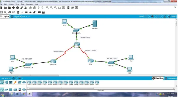
ILUSTRACIÓN 1: ELEMENTOS DE LA RED ESCENARIO 1. ... 11
ILUSTRACIÓN 2: RED ESCENARIO 1 CON DIRECCIONES IP ... 11
ILUSTRACIÓN 3: TOPOLOGÍA DE RED ESCENARIO 1 ... 16
ILUSTRACIÓN 4: EVIDENCIA DE PING DE PC1 A WS1 Y A PC4 ... 27
ILUSTRACIÓN 5: EVIDENCIA DE PING DEL SERVIDOR A TODAS LAS TERMINALES (1) ... 27
ILUSTRACIÓN 6: EVIDENCIA DE PING DEL SERVIDOR A TODAS LAS TERMINALES (2) ... 28
ILUSTRACIÓN 7: EVIDENCIA PING PC4 A PC1 Y AL SERVIDOR ... 31
ILUSTRACIÓN 8: EVIDENCIA PING ENTRE ROUTERS Y SERVIDOR ... 32
ILUSTRACIÓN 9: EVIDENCIA PING DE EXTREMO A EXTREMO ... 33
ILUSTRACIÓN 10: EVIDENCIA DE ACL DEL SERVIDOR A LAS TERMINALES ... 38
ILUSTRACIÓN 11: CONECTIVIDAD EN SUBRED MEDELLIN Y RESTRICCIÓN A OTRAS SUBREDES ... 39
ILUSTRACIÓN 12: CONECTIVIDAD EN SUBRED CALI Y RESTRICCIÓN A OTRAS SUBREDES ... 40
ILUSTRACIÓN 13: CONECTIVIDAD DEL SERVIDOR A TODOS LOS EXTREMOS ... 40
ILUSTRACIÓN 14: RED DEL ESCENARIO 2 ... 47
ILUSTRACIÓN 15: IMPLEMENTACION DE LA RED ESCENARIO 2 ... 48
ILUSTRACIÓN 16: EVIDENCIA DE CONECTIVIDAD ENTRE TERMINALES ... 61
ILUSTRACIÓN 17: CONECTIVIDAD DE VLAN 20 PC4 A PC2 Y NEGACIÓN DE SERVICIO DE INTERNET ... 62
ILUSTRACIÓN 18: PING DE PC 5 A TERMINALES Y ACCESO A SERVIDOR EXTERNO... 63
ILUSTRACIÓN 19: EVIDENCIA DE CONEXIÓN FTP A SERVIDOR EXTERNO ... 64
ILUSTRACIÓN 20: EVIDENCIA DE CONECTIVIDAD WEB A SERVIDOR EXTERNO ... 65
ILUSTRACIÓN 21: EVIDENCIA DE CONEXIÓN VLAN ENTRE VLANS 20 Y VLAN 10 ... 66
ILUSTRACIÓN 22: CONECTIVIDAD DE VLAN 30 A INTERNET Y FALLA A OTRAS TERMINALES 67 ILUSTRACIÓN 23: CONECTIVIDAD ENTRE VLAN10 Y VLANS 20 Y NEGACIÓN DE INTERNET .68 ILUSTRACIÓN 24: RESTRICCIÓN DE CONECTIVIDAD ENTRE VLANS DE DE CUNDINAMARCA 70 ILUSTRACIÓN 25: RESTRICCIÓN DE CONECTIVIDAD VLANS DE TUNJA ... 71
ILUSTRACIÓN 26: RESTRICCIÓN DE CONECTIVIDAD ENTRE VLANS DE BUCARAMANGA 72
ILUSTRACIÓN 27: TELNET DE SW-BCARAMANGA A ROUTER ... 73
ILUSTRACIÓN 28: EVIDENCIA DHCP PC0 ... 82
ILUSTRACIÓN 29: EVIDENCIA DHCP PC1 ... 83
ILUSTRACIÓN 30: EVIDENCIA DHCP PC4 ... 83
ILUSTRACIÓN 31: EVIDENCIA DHCP PC4 ... 84
INDICE DE TABLAS
TABLA 1: TABLA DE SUBNETEO DE LA RED ... 16
TABLA 2: DIRECCIONAMIENTO IP ... 17
TABLA 3: CONFIGURACIÓN BÁSICA DE ROUTERS ... 17
TABLA 4: COMPROBACION DE TABLA DE ENRUTAMIENTO ... 30
TABLA 5: PRUEBAS DEL FUNCIONAMIENTO DE LA RED ... 45
RESUMEN
ABSTRACT
During the course development, we learned techniques and protocols of data networks that allowed us to provide solutions to real problems, references to connectivity and communication on computers and servers, where you can control an effective effective continuity to the data flows in problems and raised by CISCO, we develop techniques that allow us to simulate in real time tangible problems that
we persuade and reduce. It was also possible to explore in depth the tools offered
INTRODUCCIÓN
OBJETIVOS
Objetivo general
Verificar la compresión de la temática desarrollada durante el curso mediante el correcto desarrollo de las pruebas de habilidades prácticas en donde se requiere de la implementación de los estándares de diseño y configuración de redes usando cisco packet tracer
Objetivos específicos
Interpretar las situaciones problema propuestas para la prueba de habilidades. Apropiar la temática vista durante el curso
EVALUACIÓN – PRUEBA DE HABILIDADES PRÁCTICAS CCNA
Descripción de escenarios propuestos para la prueba de habilidades
Escenario 1
Una empresa posee sucursales distribuidas en las ciudades de Bogotá, Medellín y Cali en donde el estudiante será el administrador de la red, el cual deberá configurar e interconectar entre sí cada uno de los dispositivos que forman parte del escenario, acorde con los lineamientos establecidos para el direccionamiento IP, protocolos de enrutamiento y demás aspectos que forman parte de la topología de red.
Topología de red
Los requerimientos solicitados son los siguientes:
Parte 1: Para el direccionamiento IP debe definirse una dirección de acuerdo con el número de hosts requeridos.
Parte 2: Considerar la asignación de los parámetros básicos y la detección de vecinos directamente conectados.
Parte 3: La red y subred establecidas deberán tener una interconexión total, todos los hosts deberán ser visibles y poder comunicarse entre ellos sin restricciones.
Parte 4: Implementar la seguridad en la red, se debe restringir el acceso y comunicación entre hosts de acuerdo con los requerimientos del administrador de red.
Parte 5: Comprobación total de los dispositivos y su funcionamiento en la red.
Ilustración 1: Elementos de la red Escenario 1.
Fuente: Universidad Nacional Abierta y a Distancia.
Ilustración 2: Red escenario 1 con direcciones Ip.
Red escenario 1 con direcciones Ip. Red escenario 1 con direcciones Ip. Desarrollo escenario 1
Como trabajo inicial se debe realizar lo siguiente.
Realizar las rutinas de diagnóstico y dejar los equipos listos para su
configuración (asignar nombres de equipos, asignar claves de seguridad, etc).
Ingresamos en cada no de los dispositivos Routers y Switches para asignarles la configuracion basica.
Router 1 BOGOTÁ
Router#conf terminal
Enter configuration commands, one per line. End with CNTL/Z. Router(config)#host na Router(config)#hostna Router(config)#hostname BOGOTA BOGOTA(config)#serv BOGOTA(config)#service enc BOGOTA(config)#service encry BOGOTA(config)#service pass BOGOTA(config)#service password-encryption BOGOTA(config)#bann BOGOTA(config)#banner mot
BOGOTA(config)#banner motd &Solo personal autorizado& BOGOTA(config)#enab
BOGOTA(config)#enable secr
BOGOTA(config)#enable secret class BOGOTA(config)#line cons
BOGOTA(config)#line console 0 BOGOTA(config-line)#pass BOGOTA(config-line)#password cisco BOGOTA(config-line)#login BOGOTA(config-line)#logg BOGOTA(config-line)#logging syn BOGOTA(config-line)#logging synchronous BOGOTA(config-line)#line vty 0 15
BOGOTA(config-line)#pass BOGOTA(config-line)#password cisco BOGOTA(config-line)#login BOGOTA(config-line)#logg BOGOTA(config-line)#logging syn BOGOTA(config-line)#logging synchronous BOGOTA(config-line)#no ip dom
BOGOTA(config-line)#no ip domain-lookup BOGOTA(config)#
ROUTER 2 MEDELLIN
Router>ENA Router>ENAble Router#CONF T
Enter configuration commands, one per line. End with CNTL/Z. Router(config)#
Router(config)#hostname MEDELLN MEDELLN(config)#no ip domain-lookup MEDELLN(config)#serv
MEDELLN(config)#service pass
MEDELLN(config)#service password-encryption MEDELLN(config)#ena
MEDELLN(config)#enable sec
MEDELLN(config)#enable secret class MEDELLN(config)#bann
MEDELLN(config)#banner mot
MEDELLN(config)#banner motd &SOLO PERSONAL AUTORIZADO& MEDELLN(config)#line console 0
MEDELLN(config-line)#pass MEDELLN(config-line)#password cisco MEDELLN(config-line)#login MEDELLN(config-line)#logg MEDELLN(config-line)#logging syn MEDELLN(config-line)#logging synchronous MEDELLN(config-line)#line vty 0 15
MEDELLN(config-line)#pass MEDELLN(config-line)#password cisco MEDELLN(config-line)#login MEDELLN(config-line)#logg MEDELLN(config-line)#logging syn MEDELLN(config-line)#logging synchronous MEDELLN(config-line)# MEDELLN(config-line)#copp MEDELLN(config-line)#copy run MEDELLN(config-line)#end MEDELLN#
%SYS-5-CONFIG_I: Configured from console by console MEDELLN#
ROUTER 3 CALI
Router>ena Router#conf t
Router#conf terminal
Enter configuration commands, one per line. End with CNTL/Z. Router(config)#hostname CALI
CALI(config)#no ip domain-lookup
CALI(config)#service password-encryption CALI(config)#enable secret class
CALI(config)#line console 0 CALI(config-line)#password cisco CALI(config-line)#login
CALI(config-line)#logging synchronous CALI(config-line)#line vty 0 15
CALI(config-line)#password cisco CALI(config-line)#login
CALI(config-line)#logging synchronous CALI(config-line)#
SWITCH DE BOGOTA
Switch>EN Switch#CONF T
Switch#CONF Terminal
Enter configuration commands, one per line. End with CNTL/Z. Switch(config)#HOSTNAME SW-BOGOTA
SW-BOGOTA(config)#no ip domain-lookup
SW-BOGOTA(config)#service password-encryption SW-BOGOTA(config)#enable secret class
SW-BOGOTA(config)#banner motd &SOLO PERSONAL AUTORIZADO& SW-BOGOTA(config)#line console 0
SW-BOGOTA(config-line)#password cisco SW-BOGOTA(config-line)#login
SW-BOGOTA(config-line)#logging synchronous SW-BOGOTA(config-line)#line vty 0 15
SW-BOGOTA(config-line)#password cisco SW-BOGOTA(config-line)#login SW-BOGOTA(config-line)#logging synchronous SW-BOGOTA(config-line)# SW-BOGOTA(config-line)# SW-BOGOTA(config-line)#
SWITCH DE MEDELLÍN
Switch>ENA Switch#CONF T
Switch#CONF Terminal
Enter configuration commands, one per line. End with CNTL/Z. Switch(config)#hostname SW-MEDELLIN
SW-MEDELLIN(config)#no ip domain-lookup
SW-MEDELLIN(config)#service password-encryption SW-MEDELLIN(config)#enable secret class
SW-MEDELLIN(config)#line console 0 SW-MEDELLIN(config-line)#password cisco SW-MEDELLIN(config-line)#login
SW-MEDELLIN(config-line)#logging synchronous SW-MEDELLIN(config-line)#line vty 0 15
SW-MEDELLIN(config-line)#password cisco SW-MEDELLIN(config-line)#login
SW-MEDELLIN(config-line)#logging synchronous SW-MEDELLIN(config-line)#
SWITCH DE CALI
Switch>en Switch>enable Switch#conf t
Switch#conf terminal
Enter configuration commands, one per line. End with CNTL/Z. Switch(config)#hostname SW-CALI
SW-CALI(config)#no ip domain-lookup
SW-CALI(config)#service password-encryption SW-CALI(config)#enable secret class
SW-CALI(config)#banner motd &SOLO PERSONAL AUTORIZADO& SW-CALI(config)#line console 0
SW-CALI(config-line)#password cisco SW-CALI(config-line)#login
SW-CALI(config-line)#logging synchronous SW-CALI(config-line)#line vty 0 15
SW-CALI(config-line)#password cisco SW-CALI(config-line)#login
SW-CALI(config-line)#logging synchronous SW-CALI(config-line)#
Realizar la conexión física de los equipos con base en la topología de red
Ilustración 3: Topología de red escenario 1
Configurar la topología de red, de acuerdo con las siguientes especificaciones.
Parte 1: Asignación de direcciones IP:
a. Se debe dividir (subnetear) la red creando una segmentación en ocho partes, para permitir crecimiento futuro de la red corporativa.
Tabla 1: Tabla de subneteo de la red.
TABLA DE SUBNETEO
N° SUBRED DIRECCION IP MASCARA DE SUBRED
1 BOGOTA 192.168.1.0 255.255.255.224
2 MEDELLIN 192.168.1.32 255.255.255.224
3 CALI 192.168.1.64 255.255.255.224
4 BOGOTÁ-MEDELLIN 192.168.1.96 255.255.255.224
5 BOGOTÁ-CALI 192.168.1.128 255.255.255.224
6 SEXTA RED 192.168.1.160 255.255.255.224
7 SEPTIMA RED 192.168.1.192 255.255.255.224
b. Asignar una dirección IP a la red.
Tabla 2: Direccionamiento IP
N° SUBRED DIRECCION IP
1 BOGOTA 192.168.1.0
2 MEDELLIN 192.168.1.32
3 CALI 192.168.1.64
4 BOGOTÁ-MEDELLIN 192.168.1.96
5 BOGOTÁ-CALI 192.168.1.128
6 SEXTA RED 192.168.1.160
7 SEPTIMA RED 192.168.1.192
8 OCTAVA RED 192.168.1.224
Parte 2: Configuración Básica.
a. Completar la siguiente tabla con la configuración básica de los routers, teniendo en cuenta las subredes diseñadas.
Tabla 3: Configuración básica de Routers.
R1 R2 R3
Nombre de Host MEDELLIN BOGOTA CALI
Dirección de Ip en interfaz Serial 0/0
192.168.1.99 192.168.1.98 192.168.1.131
Dirección de Ip en interfaz Serial 0/1
192.168.1.130
Dirección de Ip en interfaz FA 0/0
192.168.1.33 192.168.1.1 192.168.1.65
Protocolo de enrutamiento Eigrp Eigrp Eigrp
Sistema Autónomo 200 200 200
Afirmaciones de red 192.168.1.0 192.168.1.0 192.168.1.0
BOGOTÁ
BOGOTA#conf t
BOGOTA#conf terminal
Enter configuration commands, one per line. End with CNTL/Z. BOGOTA(config)#int
BOGOTA(config)#interface ser
BOGOTA(config-if)#ip address 192.168.1.98 255.255.255.224 BOGOTA(config-if)#no sh BOGOTA(config-if)#no shutdown BOGOTA(config-if)#exit BOGOTA(config)#int BOGOTA(config)#interface ser
BOGOTA(config)#interface serial 0/0/1 BOGOTA(config-if)#ip add
BOGOTA(config-if)#ip address 192.168.1.130 255.255.255.224 BOGOTA(config-if)#no sh
BOGOTA(config-if)#no shutdown
BOGOTA(config-if)#router eigrp 200 BOGOTA(config-router)#no auto-sumary ^
% Invalid input detected at '^' marker. BOGOTA(config-router)#no auto-sumary ^
% Invalid input detected at '^' marker. BOGOTA(config-router)#no auto-summary
BOGOTA(config-router)#do show ip route connected C 192.168.1.0/27 is directly connected, GigabitEthernet0/0 C 192.168.1.96/27 is directly connected, Serial0/0/0
C 192.168.1.128/27 is directly connected, Serial0/0/1
BOGOTA(config-router)#network 192.168.1.0 0.0.0.31 ^
% Invalid input detected at '^' marker.
BOGOTA(config-router)#network 192.168.1.0 0.0.0.31 BOGOTA(config-router)#network 192.168.96.0 0.0.0.31 BOGOTA(config-router)#network 192.168.128.0 0.0.0.31 BOGOTA(config-router)#do show ip route connected C 192.168.1.0/27 is directly connected, GigabitEthernet0/0 C 192.168.1.96/27 is directly connected, Serial0/0/0
C 192.168.1.128/27 is directly connected, Serial0/0/1
MEDELLIN
MEDELLIN>en Password:
MEDELLIN#conf t
MEDELLIN#conf terminal
MEDELLIN(config)#int s0/0/0
MEDELLIN(config-if)#ip address 192.168.1.99 255.255.255.224 MEDELLIN(config-if)#no sh
MEDELLIN(config-if)#no shutdown
MEDELLIN(config-if)#
%LINK-5-CHANGED: Interface Serial0/0/0, changed state to up
MEDELLIN(config-if)#
%LINEPROTO-5-UPDOWN: Line protocol on Interface Serial0/0/0, changed state to up
MEDELLIN(config-if)#
MEDELLIN(config-if)#int g0/0
MEDELLIN(config-if)#ip address 192.168.1.33 255.255.255.224 MEDELLIN(config-if)#no sh
MEDELLIN(config-if)#no shutdown
MEDELLIN(config-if)#
%LINK-5-CHANGED: Interface GigabitEthernet0/0, changed state to up
%LINEPROTO-5-UPDOWN: Line protocol on Interface GigabitEthernet0/0, changed state to up
MEDELLIN(config-if)#
MEDELLN>ena MEDELLN>enable Password:
MEDELLN#conf t
MEDELLN#conf terminal
Enter configuration commands, one per line. End with CNTL/Z. MEDELLN(config)#int
MEDELLN(config)#interface g
MEDELLN(config)#interface gigabitEthernet 0/0 MEDELLN(config-if)#router eigrp 200
MEDELLN(config-router)#no auto-summary
MEDELLN(config-router)#do show ip route connected C 192.168.1.32/27 is directly connected, GigabitEthernet0/0 C 192.168.1.96/27 is directly connected, Serial0/0/0
MEDELLN>enable Password:
MEDELLN#conf
Configuring from terminal, memory, or network [terminal]? t Enter configuration commands, one per line. End with CNTL/Z. MEDELLN(config)#int s
MEDELLN(config)#int serial 0/0/0 MEDELLN(config-if)#rou
MEDELLN(config-if)#router eigrp 200
MEDELLN(config-router)#network 192.168.1.0 0.0.0.31
CALI ALI>en CALI>enable Password: CALI#conf t CALI#conf terminal
Enter configuration commands, one per line. End with CNTL/Z. CALI(config)#int
CALI(config)#interface ser
CALI(config)#interface serial 0/0/0 CALI(config-if)#ip add
CALI(config-if)#ip address 192.168.1.131 % Incomplete command.
CALI(config-if)#no sh CALI(config-if)#no shutdown CALI>en CALI>enable Password: CALI#conf t CALI#conf terminal
Enter configuration commands, one per line. End with CNTL/Z. CALI(config)#int
CALI(config)#interface ser
CALI(config)#interface serial 0/0/0 CALI(config-if)#ip add
CALI(config-if)#ip address 192.168.1.131 % Incomplete command.
CALI(config-if)#no sh
CALI(config-if)#no shutdown ALI>en
CALI#conf t
CALI#conf terminal
Enter configuration commands, one per line. End with CNTL/Z. CALI(config)#int
CALI(config)#interface ser
CALI(config)#interface serial 0/0/0 CALI(config-if)#ip add
CALI(config-if)#ip address 192.168.1.131 % Incomplete command.
CALI(config-if)#no sh
CALI(config-if)#no shutdown
CALI(config)#int s0/0/0 CALI(config-if)#
CALI(config-if)#router eigrp 200
CALI(config-router)#no auto-summary
CALI(config-router)#do show ip route connected
C 192.168.1.64/27 is directly connected, GigabitEthernet0/0 C 192.168.1.128/27 is directly connected, Serial0/0/0
CALI(config-router)#networ 192.168.1.64 0.0.0.31 CALI(config-router)#networ 192.168.1.128 0.0.0.31 CALI(config-router)#
b. Después de cargada la configuración en los dispositivos, verificar la tabla de enrutamiento en cada uno de los routers para comprobar las redes y sus rutas.
BOGOTA#show ip route
Codes: L - local, C - connected, S - static, R - RIP, M - mobile, B - BGP D - EIGRP, EX - EIGRP external, O - OSPF, IA - OSPF inter area N1 - OSPF NSSA external type 1, N2 - OSPF NSSA external type 2 E1 - OSPF external type 1, E2 - OSPF external type 2, E - EGP i - IS-IS, L1 - IS-IS level-1, L2 - IS-IS level-2, ia - IS-IS inter area * - candidate default, U - per-user static route, o - ODR
P - periodic downloaded static route
Gateway of last resort is not set
192.168.1.0/24 is variably subnetted, 8 subnets, 2 masks C 192.168.1.0/27 is directly connected, GigabitEthernet0/0 L 192.168.1.1/32 is directly connected, GigabitEthernet0/0
D 192.168.1.64/27 [90/2170112] via 192.168.1.131, 00:01:04, Serial0/0/1 C 192.168.1.96/27 is directly connected, Serial0/0/0
L 192.168.1.98/32 is directly connected, Serial0/0/0 C 192.168.1.128/27 is directly connected, Serial0/0/1 L 192.168.1.130/32 is directly connected, Serial0/0/1
BOGOTA# MEDELLIN
MEDELLN#show ip route
Codes: L - local, C - connected, S - static, R - RIP, M - mobile, B - BGP D - EIGRP, EX - EIGRP external, O - OSPF, IA - OSPF inter area N1 - OSPF NSSA external type 1, N2 - OSPF NSSA external type 2 E1 - OSPF external type 1, E2 - OSPF external type 2, E - EGP i - IS-IS, L1 - IS-IS level-1, L2 - IS-IS level-2, ia - IS-IS inter area * - candidate default, U - per-user static route, o - ODR
P - periodic downloaded static route
Gateway of last resort is not set
192.168.1.0/24 is variably subnetted, 7 subnets, 2 masks
D 192.168.1.0/27 [90/2170112] via 192.168.1.98, 00:02:19, Serial0/0/0 C 192.168.1.32/27 is directly connected, GigabitEthernet0/0
L 192.168.1.33/32 is directly connected, GigabitEthernet0/0
D 192.168.1.64/27 [90/2682112] via 192.168.1.98, 00:02:19, Serial0/0/0 C 192.168.1.96/27 is directly connected, Serial0/0/0
L 192.168.1.99/32 is directly connected, Serial0/0/0
D 192.168.1.128/27 [90/2681856] via 192.168.1.98, 00:02:19, Serial0/0/0
MEDELLN#
CALI
CALI#show ip route
Codes: L - local, C - connected, S - static, R - RIP, M - mobile, B - BGP D - EIGRP, EX - EIGRP external, O - OSPF, IA - OSPF inter area N1 - OSPF NSSA external type 1, N2 - OSPF NSSA external type 2 E1 - OSPF external type 1, E2 - OSPF external type 2, E - EGP i - IS-IS, L1 - IS-IS level-1, L2 - IS-IS level-2, ia - IS-IS inter area * - candidate default, U - per-user static route, o - ODR
P - periodic downloaded static route
Gateway of last resort is not set
192.168.1.0/24 is variably subnetted, 7 subnets, 2 masks
D 192.168.1.32/27 [90/2682112] via 192.168.1.130, 00:02:37, Serial0/0/0 C 192.168.1.64/27 is directly connected, GigabitEthernet0/0
L 192.168.1.65/32 is directly connected, GigabitEthernet0/0
D 192.168.1.96/27 [90/2681856] via 192.168.1.130, 00:02:37, Serial0/0/0 C 192.168.1.128/27 is directly connected, Serial0/0/0
L 192.168.1.131/32 is directly connected, Serial0/0/0
CALI#
c. Verificar el balanceo de carga que presentan los routers.
Para la configuracion que se ha dado a los routers y especificamente teniendo en cuenta la topologia entre ellos, el balanceo de carga no se aplica porque no existen “caminos” diferentes para encomunicarse entre sí, pero a manera de prueba se puede verificar como se conecta cada dispositivo emplaendo el comando ip eigrp topology. Como se puede observar a continuación.
BOGOTA#ip eigrp topology ^
% Invalid input detected at '^' marker.
BOGOTA#show ip eigrp topology
IP-EIGRP Topology Table for AS 200/ID(192.168.1.130)
Codes: P - Passive, A - Active, U - Update, Q - Query, R - Reply, r - Reply status
P 192.168.1.0/27, 1 successors, FD is 2816 via Connected, GigabitEthernet0/0 BOGOTA#
MEDELLN#show ip eigrp topology
IP-EIGRP Topology Table for AS 200/ID(192.168.1.99)
Codes: P - Passive, A - Active, U - Update, Q - Query, R - Reply, r - Reply status
MEDELLN#
CALI#show ip eigrp topology
IP-EIGRP Topology Table for AS 200/ID(192.168.1.65)
P 192.168.1.64/27, 1 successors, FD is 2816 via Connected, GigabitEthernet0/0
P 192.168.1.128/27, 1 successors, FD is 2169856 via Connected, Serial0/0/0
CALI#
d. Realizar un diagnóstico de vecinos uando el comando cdp.
BOGOTA#show cdp neighbor
Capability Codes: R - Router, T - Trans Bridge, B - Source Route Bridge S - Switch, H - Host, I - IGMP, r - Repeater, P - Phone
Device ID Local Intrfce Holdtme Capability Platform Port ID
SW-BOGOTA Gig 0/0 175 S 2960 Gig 0/1
MEDELLN Ser 0/0/0 175 R C1900 Ser 0/0/0
CALI Ser 0/0/1 175 R C1900 Ser 0/0/0
BOGOTA#
MEDELLN#show cdp neighbor
Capability Codes: R - Router, T - Trans Bridge, B - Source Route Bridge S - Switch, H - Host, I - IGMP, r - Repeater, P - Phone
Device ID Local Intrfce Holdtme Capability Platform Port ID
SW-MEDELLIN Gig 0/0 140 S 2960 Gig 0/1
BOGOTA Ser 0/0/0 140 R C1900 Ser 0/0/0
MEDELLN#
CALI#
CALI#show cdp neighbor
Capability Codes: R - Router, T - Trans Bridge, B - Source Route Bridge S - Switch, H - Host, I - IGMP, r - Repeater, P - Phone
Device ID Local Intrfce Holdtme Capability Platform Port ID
SW-CALI Gig 0/0 150 S 2960 Gig 0/1
BOGOTA Ser 0/0/0 151 R C1900 Ser 0/0/1
CALI#
e. Realizar una prueba de conectividad en cada tramo de la ruta usando Ping.
PING DE MEDELLIN A BOGOTÁ
MEDELLN#ping 192.168.1.98
Sending 5, 100-byte ICMP Echos to 192.168.1.98, timeout is 2 seconds: !!!!!
Success rate is 100 percent (5/5), round-trip min/avg/max = 1/3/14 ms
MEDELLN#
PING DE MEDELLIN A CALI
MEDELLN#ping 192.168.1.131
Type escape sequence to abort.
Sending 5, 100-byte ICMP Echos to 192.168.1.131, timeout is 2 seconds: !!!!!
Success rate is 100 percent (5/5), round-trip min/avg/max = 2/9/33 ms
MEDELLN#
PING BOGOTÁ A MEDELLIN
BOGOTA#ping 192.168.1.99
Type escape sequence to abort.
Sending 5, 100-byte ICMP Echos to 192.168.1.99, timeout is 2 seconds: !!!!!
Success rate is 100 percent (5/5), round-trip min/avg/max = 1/4/16 ms
PING BOGOTÁ A CALI
BOGOTA#ping 192.168.1.131
Type escape sequence to abort.
Sending 5, 100-byte ICMP Echos to 192.168.1.131, timeout is 2 seconds: !!!!!
Success rate is 100 percent (5/5), round-trip min/avg/max = 1/5/25 ms BOGOTA#
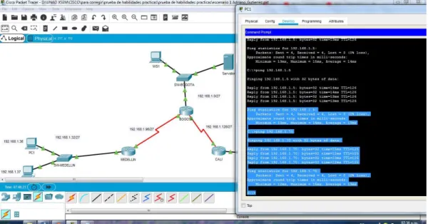
PING DE BOGOTÁ A PC WS1 BOGOTA#ping 192.168.1.5
Type escape sequence to abort.
Sending 5, 100-byte ICMP Echos to 192.168.1.5, timeout is 2 seconds: !!!!!
BOGOTA#
PING DE BOGOTÁ A SERVIDOR
BOGOTA#ping 192.168.1.6
Type escape sequence to abort.
Sending 5, 100-byte ICMP Echos to 192.168.1.6, timeout is 2 seconds: !!!!!
Success rate is 100 percent (5/5), round-trip min/avg/max = 0/1/3 ms
BOGOTA#
BOGOTA#ping 192.168.1.131
Type escape sequence to abort.
Sending 5, 100-byte ICMP Echos to 192.168.1.131, timeout is 2 seconds: !!!!!
Success rate is 100 percent (5/5), round-trip min/avg/max = 1/3/10 ms
BOGOTA#ping 192.168.1.99
Type escape sequence to abort.
Sending 5, 100-byte ICMP Echos to 192.168.1.99, timeout is 2 seconds: !!!!!
Success rate is 100 percent (5/5), round-trip min/avg/max = 1/21/100 ms
Ilustración 4: Evidencia de Ping de PC1 A WS1 y a PC4
Ilustración 6: Evidencia de ping del servidor a todas las terminales (2)
Parte 3: Configuración de Enrutamiento.
a. Asignar el protocolo de enrutamiento EIGRP a los routers considerando el direccionamiento diseñado.
BOGOTA(config-if)#router eigrp 200 BOGOTA(config-router)#no auto-sumary
^
% Invalid input detected at '^' marker.
BOGOTA(config-router)#no auto-sumary ^
% Invalid input detected at '^' marker.
BOGOTA(config-router)#no auto-summary
BOGOTA(config-router)#do show ip route connected
C 192.168.1.0/27 is directly connected, GigabitEthernet0/0 C 192.168.1.96/27 is directly connected, Serial0/0/0
C 192.168.1.128/27 is directly connected, Serial0/0/1
BOGOTA(config-router)#network 192.168.1.0 0.0.0.31 ^
BOGOTA(config-router)#network 192.168.1.0 0.0.0.31 BOGOTA(config-router)#network 192.168.96.0 0.0.0.31 BOGOTA(config-router)#network 192.168.128.0 0.0.0.31 BOGOTA(config-router)#do show ip route connected
C 192.168.1.0/27 is directly connected, GigabitEthernet0/0 C 192.168.1.96/27 is directly connected, Serial0/0/0
C 192.168.1.128/27 is directly connected, Serial0/0/1
MEDELLN(config-if)#router eigrp 200
MEDELLN(config-router)#network 192.168.1.0 0.0.0.31 MEDELLN(config-router)#do show ip route connected
C 192.168.1.32/27 is directly connected, GigabitEthernet0/0 C 192.168.1.96/27 is directly connected, Serial0/0
CALI(config-if)#router eigrp 200
CALI(config-router)#network 192.168.1.0 CALI(config-router)#
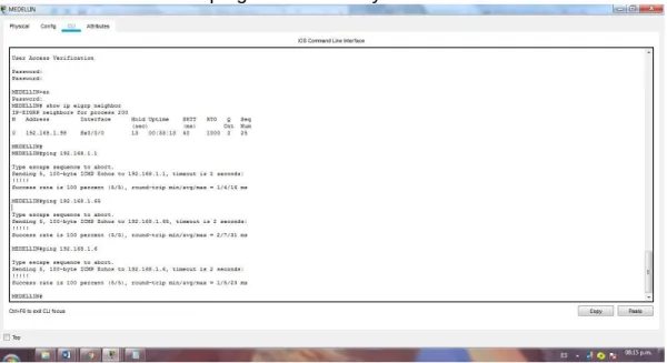
b. Verificar si existe vecindad con los routers configurados con EIGRP.
VECINOS DE MEDELLÍN
MEDELLIN# show ip eigrp neighbor IP-EIGRP neighbors for process 200
H Address Interface Hold Uptime SRTT RTO Q Seq (sec) (ms) Cnt Num
0 192.168.1.98 Se0/0/0 13 00:33:13 40 1000 0 25
VECINOS DE BOGOTÁ
BOGOTA#show ip eigrp neighbor IP-EIGRP neighbors for process 200
H Address Interface Hold Uptime SRTT RTO Q Seq (sec) (ms) Cnt Num
0 192.168.1.131 Se0/0/1 11 01:14:28 40 1000 0 23 1 192.168.1.99 Se0/0/0 13 00:36:01 40 1000 0 7
VECINOS DE CALI
CALI#show ip eigrp neighbor
IP-EIGRP neighbors for process 200
H Address Interface Hold Uptime SRTT RTO Q Seq (sec) (ms) Cnt Num
c. Realizar la comprobación de las tablas de enrutamiento en cada uno de los routers para verificar cada una de las rutas establecidas.
Tabla 4: Comprobacion de tabla de enrutamiento
R1 R2 R3
Nombre de Host MEDELLIN BOGOTA CALI
Dirección de Ip en interfaz Serial 0/0
192.168.1.99 192.168.1.98 192.168.1.131
Dirección de Ip en interfaz Serial 0/1
192.168.1.130
Dirección de Ip en interfaz FA 0/0
192.168.1.33 192.168.1.1 192.168.1.65
Protocolo de enrutamiento Eigrp Eigrp Eigrp
Sistema Autónomo 200 200 200
Afirmaciones de red 192.168.1.0 192.168.1.0 192.168.1.0
d. Realizar un diagnóstico para comprobar que cada uno de los puntos de la red se puedan ver y tengan conectividad entre sí. Realizar esta prueba desde un host de la red LAN del router CALI, primero a la red de MEDELLIN y luego al servidor.
PING DE PC4 A PC1
Pinging 192.168.1.36 with 32 bytes of data:
Reply from 192.168.1.36: bytes=32 time=12ms TTL=125 Reply from 192.168.1.36: bytes=32 time=12ms TTL=125 Reply from 192.168.1.36: bytes=32 time=9ms TTL=125 Reply from 192.168.1.36: bytes=32 time=12ms TTL=125
Ping statistics for 192.168.1.36:
Packets: Sent = 4, Received = 4, Lost = 0 (0% loss), Approximate round trip times in milli-seconds:
Minimum = 9ms, Maximum = 12ms, Average = 11ms
C:\>
PING PC4 AL SERVIDOR C:\>ping 192.168.1.6
Pinging 192.168.1.6 with 32 bytes of data:
Reply from 192.168.1.6: bytes=32 time=10ms TTL=126 Reply from 192.168.1.6: bytes=32 time=14ms TTL=126
Ping statistics for 192.168.1.6:
Packets: Sent = 4, Received = 4, Lost = 0 (0% loss), Approximate round trip times in milli-seconds:
Minimum = 10ms, Maximum = 14ms, Average = 12ms
Ilustración 7: Evidencia ping pc4 a pc1 y al servidor.
PING DESDE MEDELLIN A TODOS LOS ROUTERS Y AL SERVIDOR
MEDELLIN#ping 192.168.1.1
Type escape sequence to abort.
Sending 5, 100-byte ICMP Echos to 192.168.1.1, timeout is 2 seconds: !!!!!
Success rate is 100 percent (5/5), round-trip min/avg/max = 1/4/16 ms
MEDELLIN#ping 192.168.1.65
Type escape sequence to abort.
Sending 5, 100-byte ICMP Echos to 192.168.1.65, timeout is 2 seconds: !!!!!
Success rate is 100 percent (5/5), round-trip min/avg/max = 2/7/31 ms
Type escape sequence to abort.
Sending 5, 100-byte ICMP Echos to 192.168.1.6, timeout is 2 seconds: !!!!!
Success rate is 100 percent (5/5), round-trip min/avg/max = 1/5/23 ms
MEDELLIN#
Ilustración 8: Evidencia ping entre routers y servidor
PING DE EXTREMO A EXTREMO C:\>ping 192.168.1.70
Pinging 192.168.1.70 with 32 bytes of data:
Reply from 192.168.1.70: bytes=32 time=23ms TTL=126 Reply from 192.168.1.70: bytes=32 time=11ms TTL=126 Reply from 192.168.1.70: bytes=32 time=11ms TTL=126 Reply from 192.168.1.70: bytes=32 time=11ms TTL=126
Ping statistics for 192.168.1.70:
Packets: Sent = 4, Received = 4, Lost = 0 (0% loss), Approximate round trip times in milli-seconds:
Minimum = 11ms, Maximum = 23ms, Average = 14ms
Pinging 192.168.1.36 with 32 bytes of data:
Reply from 192.168.1.36: bytes=32 time=12ms TTL=126 Reply from 192.168.1.36: bytes=32 time=16ms TTL=126 Reply from 192.168.1.36: bytes=32 time=14ms TTL=126 Reply from 192.168.1.36: bytes=32 time=14ms TTL=126
Ping statistics for 192.168.1.36:
Packets: Sent = 4, Received = 4, Lost = 0 (0% loss), Approximate round trip times in milli-seconds:
Minimum = 12ms, Maximum = 16ms, Average = 14ms
C:\>ping 192.168.1.37
Pinging 192.168.1.37 with 32 bytes of data:
Reply from 192.168.1.37: bytes=32 time=27ms TTL=126 Reply from 192.168.1.37: bytes=32 time=11ms TTL=126 Reply from 192.168.1.37: bytes=32 time=14ms TTL=126 Reply from 192.168.1.37: bytes=32 time=13ms TTL=126
Ping statistics for 192.168.1.37:
Packets: Sent = 4, Received = 4, Lost = 0 (0% loss), Approximate round trip times in milli-seconds:
Minimum = 11ms, Maximum = 27ms, Average = 16ms
Parte 4: Configuración de las listas de Control de Acceso.
En este momento cualquier usuario de la red tiene acceso a todos sus dispositivos y estaciones de trabajo. El jefe de redes le solicita implementar seguridad en la red. Para esta labor se decide configurar listas de control de acceso (ACL) a los routers. Las condiciones para crear las ACL son las siguientes:
a. Cada router debe estar habilitado para establecer conexiones Telnet con los demás routers y tener acceso a cualquier dispositivo en la red.
La seguridad de los routers se configuró al inicio del documento mediante el comando enable secret class y password cisco
La cofiguracion a telnet se realizó cuando se configuró la línea de consola 0 y vty 0 15 pero a solicitud de la guía de trabajo se consignan los comandos en cada router
ROUTER BOGOTÁ
SW-BOGOTA(config)#line console 0 SW-BOGOTA(config-line)#password cisco SW-BOGOTA(config-line)#login
SW-BOGOTA(config-line)#logging synchronous SW-BOGOTA(config-line)#line vty 0 15
SW-BOGOTA(config-line)#password cisco SW-BOGOTA(config-line)#login
SW-BOGOTA(config-line)#logging synchronous
ROUTER MEDELLÍN
SW-MEDELLIN(config)#line console 0 SW-MEDELLIN(config-line)#password cisco SW-MEDELLIN(config-line)#login
SW-MEDELLIN(config-line)#logging synchronous SW-MEDELLIN(config-line)#line vty 0 15
SW-MEDELLIN(config-line)#password cisco SW-MEDELLIN(config-line)#login
SW-MEDELLIN(config-line)#logging synchronous
ROUTER CALI
SW-CALI(config)#line console 0 SW-CALI(config-line)#password cisco SW-CALI(config-line)#login
SW-CALI(config-line)#line vty 0 15 SW-CALI(config-line)#password cisco SW-CALI(config-line)#login
SW-CALI(config-line)#logging synchronous
b. El equipo WS1 y el servidor se encuentran en la subred de administración. Solo el servidor de la subred de administración debe tener acceso a cualquier otro dispositivo en cualquier parte de la red.
ACL MEDELLÍN MEDELLIN>en Password:
MEDELLIN#conf t
MEDELLIN#conf terminal
Enter configuration commands, one per line. End with CNTL/Z. MEDELLIN(config)#acc
MEDELLIN(config)#access-list 101 per
MEDELLIN(config)#access-list 101 permit ip 192.168.1.32 0.0.0.31 host 192.168.1.6
MEDELLIN(config)#int g
MEDELLIN(config)#int gigabitEthernet 0/0 MEDELLIN(config-if)#ip access-group 101 in MEDELLIN(config-if)#
ACL CALI CALI# CALI#conf t
CALI#conf terminal
Enter configuration commands, one per line. End with CNTL/Z. CALI(config)#acc
CALI(config)#access-list 101 per
CALI(config)#access-list 101 permit ip 192.168.1.64 0.0.0.31 host 192.168.1.6 CALI(config)#int g
CALI(config)#int gigabitEthernet 0/0 CALI(config-if)#ip access-group 101 in CALI(config-if)#
COMPROBACION DE LA LISTA DE CONTROL DE ACCESO
Pinging 192.168.1.6 with 32 bytes of data:
Reply from 192.168.1.6: bytes=32 time=15ms TTL=126
Ping statistics for 192.168.1.6:
Packets: Sent = 4, Received = 4, Lost = 0 (0% loss), Approximate round trip times in milli-seconds:
Minimum = 11ms, Maximum = 15ms, Average = 12ms
C:\>ping 192.168.1.5
Pinging 192.168.1.5 with 32 bytes of data:
Reply from 192.168.1.33: Destination host unreachable. Reply from 192.168.1.33: Destination host unreachable. Reply from 192.168.1.33: Destination host unreachable. Reply from 192.168.1.33: Destination host unreachable.
Ping statistics for 192.168.1.5:
Packets: Sent = 4, Received = 0, Lost = 4 (100% loss),
Pinging 192.168.1.3 with 32 bytes of data:
Reply from 192.168.1.33: Destination host unreachable. Reply from 192.168.1.33: Destination host unreachable. Reply from 192.168.1.33: Destination host unreachable. Reply from 192.168.1.33: Destination host unreachable.
Ping statistics for 192.168.1.3:
Packets: Sent = 4, Received = 0, Lost = 4 (100% loss),
Ahora se configura la ACL para que el servidor pueda acceder a todos los dispositivos de la red mediante el siguiente commando
ACL PARA EL SERVIDOR BOGOTA>en
Password: BOGOTA#conf t
BOGOTA#conf terminal
Enter configuration commands, one per line. End with CNTL/Z. BOGOTA(config)#access-list 101 permit ip host 192.168.1.6 any BOGOTA(config)#int g0/0
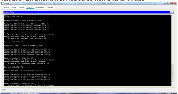
COMPROBACION DE ACCESO DEL SERVIDOR A LAS TERMINALES C:\>ping 192.168.1.5
Pinging 192.168.1.5 with 32 bytes of data:
Reply from 192.168.1.5: bytes=32 time=1ms TTL=128 Reply from 192.168.1.5: bytes=32 time=3ms TTL=128 Reply from 192.168.1.5: bytes=32 time<1ms TTL=128 Reply from 192.168.1.5: bytes=32 time<1ms TTL=128
Ping statistics for 192.168.1.5:
Packets: Sent = 4, Received = 4, Lost = 0 (0% loss), Approximate round trip times in milli-seconds:
Minimum = 0ms, Maximum = 3ms, Average = 1ms
C:\>ping 192.168.1.37
Pinging 192.168.1.37 with 32 bytes of data:
Reply from 192.168.1.37: bytes=32 time=13ms TTL=126 Reply from 192.168.1.37: bytes=32 time=14ms TTL=126 Reply from 192.168.1.37: bytes=32 time=12ms TTL=126 Reply from 192.168.1.37: bytes=32 time=11ms TTL=126
Ping statistics for 192.168.1.37:
Packets: Sent = 4, Received = 4, Lost = 0 (0% loss), Approximate round trip times in milli-seconds:
Minimum = 11ms, Maximum = 14ms, Average = 12ms
C:\>ping 192.168.1.70
Pinging 192.168.1.70 with 32 bytes of data:
Reply from 192.168.1.70: bytes=32 time=26ms TTL=126 Reply from 192.168.1.70: bytes=32 time=16ms TTL=126 Reply from 192.168.1.70: bytes=32 time=11ms TTL=126 Reply from 192.168.1.70: bytes=32 time=14ms TTL=126
Ping statistics for 192.168.1.70:
Packets: Sent = 4, Received = 4, Lost = 0 (0% loss), Approximate round trip times in milli-seconds:
Ilustración 10: Evidencia de ACL del servidor a las terminales
c. Las estaciones de trabajo en las LAN de MEDELLIN y CALI no deben tener acceso a ningún dispositivo fuera de su subred, excepto para interconectar con el servidor.
MEDELLIN(config)#access-list 101 permit ip 192.168.1.32 0.0.0.31 host 192.168.1.6
MEDELLIN(config)#int g
MEDELLIN(config)#int gigabitEthernet 0/0 MEDELLIN(config-if)#ip access-group 101 in
CALI(config)#access-list 101 permit ip 192.168.1.64 0.0.0.31 host 192.168.1.6 CALI(config)#int g
CALI(config)#int gigabitEthernet 0/0 CALI(config-if)#ip access-group 101 in
COMPROBACION DE LA RESTRICCION DE CADA SUBRED
Pinging 192.168.1.70 with 32 bytes of data:
Ping statistics for 192.168.1.70:
Packets: Sent = 4, Received = 0, Lost = 4 (100% loss),
Pinging 192.168.1.36 with 32 bytes of data:
Reply from 192.168.1.65: Destination host unreachable. Reply from 192.168.1.65: Destination host unreachable. Reply from 192.168.1.65: Destination host unreachable. Reply from 192.168.1.65: Destination host unreachable.
Ping statistics for 192.168.1.36:
Packets: Sent = 4, Received = 0, Lost = 4 (100% loss),
Ilustración 12: Conectividad en subred Cali y restricción a otras subredes
Parte 5: Comprobación de la red instalada.
a. Se debe probar que la configuración de las listas de acceso fue exitosa.
ACL SERVIDOR C:\>ping 192.168.1.5
Pinging 192.168.1.5 with 32 bytes of data:
Reply from 192.168.1.5: bytes=32 time=1ms TTL=128 Reply from 192.168.1.5: bytes=32 time<1ms TTL=128 Reply from 192.168.1.5: bytes=32 time<1ms TTL=128 Reply from 192.168.1.5: bytes=32 time<1ms TTL=128
Ping statistics for 192.168.1.5:
Packets: Sent = 4, Received = 4, Lost = 0 (0% loss), Approximate round trip times in milli-seconds:
Minimum = 0ms, Maximum = 1ms, Average = 0ms
C:\>ping 192.168.1.71
Pinging 192.168.1.71 with 32 bytes of data:
Reply from 192.168.1.71: bytes=32 time=2ms TTL=126 Reply from 192.168.1.71: bytes=32 time=14ms TTL=126 Reply from 192.168.1.71: bytes=32 time=11ms TTL=126 Reply from 192.168.1.71: bytes=32 time=14ms TTL=126
Ping statistics for 192.168.1.71:
Packets: Sent = 4, Received = 4, Lost = 0 (0% loss), Approximate round trip times in milli-seconds:
Minimum = 2ms, Maximum = 14ms, Average = 10ms
C:\>ping 192.168.1.37
Pinging 192.168.1.37 with 32 bytes of data:
Ping statistics for 192.168.1.37:
Packets: Sent = 4, Received = 4, Lost = 0 (0% loss), Approximate round trip times in milli-seconds:
Minimum = 11ms, Maximum = 27ms, Average = 16ms
C:\>ping 192.168.1.1
Pinging 192.168.1.1 with 32 bytes of data:
Reply from 192.168.1.1: bytes=32 time=1ms TTL=255 Reply from 192.168.1.1: bytes=32 time<1ms TTL=255 Reply from 192.168.1.1: bytes=32 time<1ms TTL=255 Reply from 192.168.1.1: bytes=32 time<1ms TTL=255
Ping statistics for 192.168.1.1:
Packets: Sent = 4, Received = 4, Lost = 0 (0% loss), Approximate round trip times in milli-seconds:
Minimum = 0ms, Maximum = 1ms, Average = 0ms
C:\>ping 192.168.1.33
Pinging 192.168.1.33 with 32 bytes of data:
Reply from 192.168.1.33: bytes=32 time=2ms TTL=254 Reply from 192.168.1.33: bytes=32 time=18ms TTL=254 Reply from 192.168.1.33: bytes=32 time=1ms TTL=254 Reply from 192.168.1.33: bytes=32 time=2ms TTL=254
Ping statistics for 192.168.1.33:
Packets: Sent = 4, Received = 4, Lost = 0 (0% loss), Approximate round trip times in milli-seconds:
Minimum = 1ms, Maximum = 18ms, Average = 5ms
C:\>ping 192.168.1.131
Pinging 192.168.1.131 with 32 bytes of data:
Reply from 192.168.1.131: bytes=32 time=2ms TTL=254 Reply from 192.168.1.131: bytes=32 time=1ms TTL=254 Reply from 192.168.1.131: bytes=32 time=1ms TTL=254 Reply from 192.168.1.131: bytes=32 time=1ms TTL=254
Ping statistics for 192.168.1.131:
Approximate round trip times in milli-seconds: Minimum = 1ms, Maximum = 2ms, Average = 1ms
ACL BOGOTA
C:\>ping 192.168.1.6
Pinging 192.168.1.6 with 32 bytes of data:
Reply from 192.168.1.6: bytes=32 time=1ms TTL=128 Reply from 192.168.1.6: bytes=32 time<1ms TTL=128 Reply from 192.168.1.6: bytes=32 time<1ms TTL=128 Reply from 192.168.1.6: bytes=32 time=3ms TTL=128
Ping statistics for 192.168.1.6:
Packets: Sent = 4, Received = 4, Lost = 0 (0% loss), Approximate round trip times in milli-seconds:
Minimum = 0ms, Maximum = 3ms, Average = 1ms
C:\>ping 192.168.1.36
Pinging 192.168.1.36 with 32 bytes of data:
Reply from 192.168.1.1: Destination host unreachable. Reply from 192.168.1.1: Destination host unreachable. Reply from 192.168.1.1: Destination host unreachable. Reply from 192.168.1.1: Destination host unreachable.
Ping statistics for 192.168.1.36:
Packets: Sent = 4, Received = 0, Lost = 4 (100% loss),
C:\>ping 192.168.1.70
Pinging 192.168.1.70 with 32 bytes of data:
Reply from 192.168.1.1: Destination host unreachable. Reply from 192.168.1.1: Destination host unreachable. Reply from 192.168.1.1: Destination host unreachable. Reply from 192.168.1.1: Destination host unreachable.
Ping statistics for 192.168.1.70:
Packets: Sent = 4, Received = 0, Lost = 4 (100% loss),
Pinging 192.168.1.37 with 32 bytes of data:
Reply from 192.168.1.37: bytes=32 time=1ms TTL=128 Reply from 192.168.1.37: bytes=32 time=1ms TTL=128 Reply from 192.168.1.37: bytes=32 time<1ms TTL=128 Reply from 192.168.1.37: bytes=32 time=3ms TTL=128
Ping statistics for 192.168.1.37:
Packets: Sent = 4, Received = 4, Lost = 0 (0% loss), Approximate round trip times in milli-seconds:
Minimum = 0ms, Maximum = 3ms, Average = 1ms
C:\>ping 192.168.1.70
Pinging 192.168.1.70 with 32 bytes of data:
Reply from 192.168.1.33: Destination host unreachable. Reply from 192.168.1.33: Destination host unreachable. Reply from 192.168.1.33: Destination host unreachable. Reply from 192.168.1.33: Destination host unreachable.
Ping statistics for 192.168.1.70:
Packets: Sent = 4, Received = 0, Lost = 4 (100% loss),
C:\>ping 192.168.1.5
Pinging 192.168.1.5 with 32 bytes of data:
Reply from 192.168.1.33: Destination host unreachable. Reply from 192.168.1.33: Destination host unreachable. Reply from 192.168.1.33: Destination host unreachable. Reply from 192.168.1.33: Destination host unreachable.
Ping statistics for 192.168.1.5:
Packets: Sent = 4, Received = 0, Lost = 4 (100% loss),
ACL CALI
C:\>ping 192.168.1.70
Pinging 192.168.1.70 with 32 bytes of data:
Reply from 192.168.1.70: bytes=32 time=3ms TTL=128 Reply from 192.168.1.70: bytes=32 time=1ms TTL=128
Ping statistics for 192.168.1.70:
Packets: Sent = 4, Received = 4, Lost = 0 (0% loss), Approximate round trip times in milli-seconds:
Minimum = 1ms, Maximum = 58ms, Average = 16ms
C:\>ping 192.168.1.37
Pinging 192.168.1.37 with 32 bytes of data:
Request timed out.
Reply from 192.168.1.65: Destination host unreachable. Reply from 192.168.1.65: Destination host unreachable. Reply from 192.168.1.65: Destination host unreachable.
Ping statistics for 192.168.1.37:
Packets: Sent = 4, Received = 0, Lost = 4 (100% loss),
C:\>ping 192.168.1.5
Pinging 192.168.1.5 with 32 bytes of data:
Reply from 192.168.1.65: Destination host unreachable. Reply from 192.168.1.65: Destination host unreachable. Reply from 192.168.1.65: Destination host unreachable. Reply from 192.168.1.65: Destination host unreachable.
Ping statistics for 192.168.1.5:
Packets: Sent = 4, Received = 0, Lost = 4 (100% loss),
b. Comprobar y Completar la siguiente tabla de condiciones de prueba para confirmar el óptimo funcionamiento de la red e.
Tabla 5: Pruebas del funcionamiento de la red
ORIGEN DESTINO RESULTADO
TELNET
Router MEDELLIN Router CALI ok
WS_1 Router BOGOTA falla
Servidor Router CALI ok
TELNET
LAN del Router
MEDELLIN Router CALI falla
LAN del Router CALI Router CALI falla
LAN del Router
MEDELLIN Router MEDELLIN falla
LAN del Router CALI Router MEDELLIN falla
PING
LAN del Router CALI WS_1 falla
LAN del Router
MEDELLIN WS_1 falla
LAN del Router
MEDELLIN LAN del Router CALI falla
PING
LAN del Router CALI Servidor ok
LAN del Router
MEDELLIN Servidor ok
Servidor LAN MEDELLIN del Router ok
Servidor LAN del Router CALI ok
Router CALI LAN del Router
MEDELLIN falla
Escenario 2
Una empresa tiene la conexión a internet en una red Ethernet, lo cual deben adaptarlo para facilitar que sus routers y las redes que incluyen puedan, por esa vía, conectarse a internet, pero empleando las direcciones de la red LAN original.
Ilustración 14: Red del escenario 2
Desarrollo del escenario 2
Los siguientes son los requerimientos necesarios:
Ilustración 15: implementacion de la red escenario 2
1. Todos los routers deberán tener lo siguiente:
Configuración básica.
ROUTER BUCARAMANGA
Router>en Router#conf t
Router#conf terminal
Enter configuration commands, one per line. End with CNTL/Z. Router(config)#no ip domain-lookup
Router(config)#service password-encryption
Router(config)#banner motd &...ATENCION SOLO ACCESO AUTORIZADO!!& Router(config)#enable secret class
Router(config)#line console 0 Router(config-line)#password cisco Router(config-line)#login
Router(config-line)#logging synchronous Router(config-line)#line vty 0 15
Router(config-line)#password cisco Router(config-line)#login
Router(config-line)#logging synchronous Router(config-line)#hostname
^
% Invalid input detected at '^' marker. Router(config-line)#
BUCARAMANGA(config)#! BUCARAMANGA#
CONFIGURACION DE INTERFACES ROUTER BUCARAMANGA
BUCARAMANGA(config)#int g0/0.1
BUCARAMANGA(config-subif)#encapsulation dot BUCARAMANGA(config-subif)#encapsulation dot1Q 1
BUCARAMANGA(config-subif)#ip address 172.31.2.1 255.255.255.248 BUCARAMANGA(config-subif)#int g0/0.10
BUCARAMANGA(config-subif)#enc
BUCARAMANGA(config-subif)#encapsulation do
BUCARAMANGA(config-subif)#encapsulation dot1Q 10 BUCARAMANGA(config-subif)#ip add
BUCARAMANGA(config-subif)#ip address 172.31.0.1 255.255.255.192 BUCARAMANGA(config-subif)#int g0/0.30
BUCARAMANGA(config-subif)#enc
BUCARAMANGA(config-subif)#encapsulation do
BUCARAMANGA(config-subif)#encapsulation dot1Q 30 BUCARAMANGA(config-subif)#ip add
BUCARAMANGA(config-subif)#ip address 172.31.0.65 255.255.255.192 BUCARAMANGA(config-subif)#int g0/0
BUCARAMANGA(config-if)#no shut BUCARAMANGA(config-if)#no shutdown
BUCARAMANGA(config-if)#
%LINK-5-CHANGED: Interface GigabitEthernet0/0, changed state to up
%LINEPROTO-5-UPDOWN: Line protocol on Interface GigabitEthernet0/0, changed state to up
%LINK-5-CHANGED: Interface GigabitEthernet0/0.1, changed state to up
%LINEPROTO-5-UPDOWN: Line protocol on Interface GigabitEthernet0/0.1, changed state to up
%LINK-5-CHANGED: Interface GigabitEthernet0/0.10, changed state to up
%LINEPROTO-5-UPDOWN: Line protocol on Interface GigabitEthernet0/0.10, changed state to up
%LINEPROTO-5-UPDOWN: Line protocol on Interface GigabitEthernet0/0.30, changed state to up
BUCARAMANGA(config-if)#
BUCARAMANGA(config-if)#int s0/0/0 BUCARAMANGA(config-if)#ip add
BUCARAMANGA(config-if)#ip address 172.31.2.34 255.255.255.252 BUCARAMANGA(config-if)#no shut
BUCARAMANGA(config-if)#no shutdown
%LINK-5-CHANGED: Interface Serial0/0/0, changed state to down BUCARAMANGA(config-if)#!
BUCARAMANGA#
%SYS-5-CONFIG_I: Configured from console by console
BUCARAMANGA#
ROUTER TUNJA
Router>en Router#conf t
Router#conf terminal
Enter configuration commands, one per line. End with CNTL/Z. Router(config)#no ip domain-lookup
Router(config)#service password-encryption
Router(config)#banner motd &...ATENCION SOLO ACCESO AUTORIZADO!!& Router(config)#enable secret class
Router(config)#line console 0 Router(config-line)#password cisco Router(config-line)#login
Router(config-line)#logging synchronous Router(config-line)#line vty 0 15
Router(config-line)#password cisco Router(config-line)#login
Router(config-line)#logging synchronous Router(config-line)#hostname TUNJA TUNJA(config)#end
CONFIGURACION DE INTERFACES ROUTER TUNJA
TUNJA>en Password: TUNJA#conf t
Enter configuration commands, one per line. End with CNTL/Z. TUNJA(config)#
TUNJA(config)#int g0/0.1 TUNJA(config-subif)#enc
TUNJA(config-subif)#encapsulation do TUNJA(config-subif)#encapsulation dot1Q 1 TUNJA(config-subif)#ip add
TUNJA(config-subif)#ip address 172.3.2.9 255.255.255.248 TUNJA(config-subif)#int g0/0.20
TUNJA(config-subif)#enc
TUNJA(config-subif)#encapsulation do
TUNJA(config-subif)#encapsulation dot1Q 20 TUNJA(config-subif)#ip add
TUNJA(config-subif)#ip address 172.31.0.129 255.255.255.192 TUNJA(config-subif)#int g0/0.30
TUNJA(config-subif)#enc
TUNJA(config-subif)#encapsulation do
TUNJA(config-subif)#encapsulation dot1Q 30 TUNJA(config-subif)#ip add
TUNJA(config-subif)#ip address 172.31.0.193 255.255.255.192 TUNJA(config-subif)#int g0/0
TUNJA(config-if)#no shut TUNJA(config-if)#no shutdown
TUNJA(config-if)#
%LINK-5-CHANGED: Interface GigabitEthernet0/0, changed state to up
%LINEPROTO-5-UPDOWN: Line protocol on Interface GigabitEthernet0/0, changed state to up
%LINK-5-CHANGED: Interface GigabitEthernet0/0.1, changed state to up
%LINEPROTO-5-UPDOWN: Line protocol on Interface GigabitEthernet0/0.1, changed state to up
%LINK-5-CHANGED: Interface GigabitEthernet0/0.20, changed state to up
%LINEPROTO-5-UPDOWN: Line protocol on Interface GigabitEthernet0/0.20, changed state to up
%LINK-5-CHANGED: Interface GigabitEthernet0/0.30, changed state to up
TUNJA(config-if)# TUNJA(config-if)#
TUNJA(config-if)#int s0/0/0 TUNJA(config-if)#ip add
TUNJA(config-if)#ip address 172.31.2.33 255.255.255.252 TUNJA(config-if)#no shu
TUNJA(config-if)#no shutdown TUNJA(config-if)#
%LINK-5-CHANGED: Interface Serial0/0/0, changed state to up
TUNJA(config-if)#
%LINEPROTO-5-UPDOWN: Line protocol on Interface Serial0/0/0, changed state to up
TUNJA(config-if)#
TUNJA(config-if)#int s0/0/1 TUNJA(config-if)#ip add
TUNJA(config-if)#ip address 172.31.2.37 255.255.255.252 TUNJA(config-if)#no shut
TUNJA(config-if)#no shutdown
%LINK-5-CHANGED: Interface Serial0/0/1, changed state to down TUNJA(config-if)#
ROUTER CUNDINAMARCA
Router>en Router>enable Router#conf t
Enter configuration commands, one per line. End with CNTL/Z. Router(config)#no ip domain-lookup
Router(config)#service password-encryption
Router(config)#banner motd &...ATENCION SOLO ACCESO AUTORIZADO!!& Router(config)#enable secret class
Router(config)#line console 0 Router(config-line)#password cisco Router(config-line)#login
Router(config-line)#logging synchronous Router(config-line)#line vty 0 15
Router(config-line)#password cisco Router(config-line)#login
Router(config-line)#hostname CUNDINAMARCA CUNDINAMARCA(config)#end
CUNDINAMARCA#
CONFIGURACION DE INTERFACES ROUTER CUNDINAMARCA
CUNDINAMARCA>en CUNDINAMARCA>enable Password:
CUNDINAMARCA#conf t
Enter configuration commands, one per line. End with CNTL/Z. CUNDINAMARCA(config)#int g0/0.1
CUNDINAMARCA(config-subif)#enc
CUNDINAMARCA(config-subif)#encapsulation do CUNDINAMARCA(config-subif)#encapsulation dot1Q 1 CUNDINAMARCA(config-subif)#ip add
CUNDINAMARCA(config-subif)#ip address 172.31.2.9 255.255.255.248 CUNDINAMARCA(config-subif)#int g0/0.20
CUNDINAMARCA(config-subif)#enc
CUNDINAMARCA(config-subif)#encapsulation do
CUNDINAMARCA(config-subif)#encapsulation dot1Q 20 CUNDINAMARCA(config-subif)#ip add
CUNDINAMARCA(config-subif)#ip address 172.31.1.65 255.255.255.192 CUNDINAMARCA(config-subif)#int g0/0.30
CUNDINAMARCA(config-subif)#enc
CUNDINAMARCA(config-subif)#encapsulation do
CUNDINAMARCA(config-subif)#encapsulation dot1Q 30 CUNDINAMARCA(config-subif)#ip add
CUNDINAMARCA(config-subif)#ip address 172.31.1.1 255.255.255.192 CUNDINAMARCA(config-subif)#int g0/0.88
CUNDINAMARCA(config-subif)#enc
CUNDINAMARCA(config-subif)#encapsulation do
CUNDINAMARCA(config-subif)#encapsulation dot1Q 88 CUNDINAMARCA(config-subif)#ip add
CUNDINAMARCA(config-subif)#ip address 172.31.2.25 255.255.255.248 CUNDINAMARCA(config-subif)#int g0/0
CUNDINAMARCA(config-if)#no shu CUNDINAMARCA(config-if)#no shutdown
CUNDINAMARCA(config-if)#
%LINEPROTO-5-UPDOWN: Line protocol on Interface GigabitEthernet0/0, changed state to up
%LINK-5-CHANGED: Interface GigabitEthernet0/0.1, changed state to up
%LINEPROTO-5-UPDOWN: Line protocol on Interface GigabitEthernet0/0.1, changed state to up
%LINK-5-CHANGED: Interface GigabitEthernet0/0.20, changed state to up
%LINEPROTO-5-UPDOWN: Line protocol on Interface GigabitEthernet0/0.20, changed state to up
%LINK-5-CHANGED: Interface GigabitEthernet0/0.30, changed state to up
%LINEPROTO-5-UPDOWN: Line protocol on Interface GigabitEthernet0/0.30, changed state to up
%LINK-5-CHANGED: Interface GigabitEthernet0/0.88, changed state to up
%LINEPROTO-5-UPDOWN: Line protocol on Interface GigabitEthernet0/0.88, changed state to up
CUNDINAMARCA(config-if)# CUNDINAMARCA(config-if)#
CUNDINAMARCA(config-if)#int s0/0/0 CUNDINAMARCA(config-if)#ip add
CUNDINAMARCA(config-if)#ip address 172.31.2.38 255.255.255.252 CUNDINAMARCA(config-if)#no shu
CUNDINAMARCA(config-if)#no shutdown
CUNDINAMARCA(config-if)#
%LINK-5-CHANGED: Interface Serial0/0/0, changed state to up
CUNDINAMARCA(config-if)#
CONFIGURACION RED EXTERNA
Username:
Username: admin Password:
Password: TUNJA#conf t
Enter configuration commands, one per line. End with CNTL/Z. TUNJA(config)#
TUNJA(config)#int g0/1 TUNJA(config-if)#ip add
TUNJA(config-if)#ip address 209.165.220.1 255.255.255.0 TUNJA(config-if)#no shu
TUNJA(config-if)#no shutdown
TUNJA(config-if)#
%LINK-5-CHANGED: Interface GigabitEthernet0/1, changed state to up
%LINEPROTO-5-UPDOWN: Line protocol on Interface GigabitEthernet0/1, changed state to up
TUNJA(config-if)#
Autenticación local con AAA.
ROUTER BUCARAMANGA
BUCARAMANGA>en Password:
BUCARAMANGA# BUCARAMANGA#conf t
BUCARAMANGA#conf terminal
Enter configuration commands, one per line. End with CNTL/Z. BUCARAMANGA(config)#username admin secret admin123 BUCARAMANGA(config)#AAA new-model
BUCARAMANGA(config)#AAA authentication login AUTHLOCAL local BUCARAMANGA(config)#line console 0
BUCARAMANGA(config-line)#login authentication AUTHLOCAL BUCARAMANGA(config-line)#line vty 0 15
BUCARAMANGA(config-line)#login authentication AUTHLOCAL BUCARAMANGA(config-line)#
ROUTER TUNJA
TUNJA#conf t
TUNJA#conf terminal
Enter configuration commands, one per line. End with CNTL/Z. TUNJA(config)#username admin secret admin123
TUNJA(config)#AAA new-model
TUNJA(config)#AAA authentication login AUTHLOCAL local TUNJA(config)#line console 0
TUNJA(config-line)#login authentication AUTHLOCAL TUNJA(config-line)#line vty 0 15
TUNJA(config-line)#login authentication AUTHLOCAL TUNJA(config-line)#
ROUTER CUNDINAMARCA
CUNDINAMARCA>en Password:
CUNDINAMARCA#conf t
CUNDINAMARCA#conf terminal
Enter configuration commands, one per line. End with CNTL/Z. CUNDINAMARCA(config)#username admin secret admin123 CUNDINAMARCA(config)#AAA new-model
CUNDINAMARCA(config)#AAA authentication login AUTHLOCAL local CUNDINAMARCA(config)#line console 0
CUNDINAMARCA(config-line)#login authentication AUTHLOCAL CUNDINAMARCA(config-line)#line vty 0 15
CUNDINAMARCA(config-line)#login authentication AUTHLOCAL CUNDINAMARCA(config-line)#
Cifrado de contraseñas.
El cifrado con contraseñas se efectúo en la configuración básica usando el comando service password-encryption, pero para efectos del desarrollo de la guía de trabajo se presentan a continuación.
Router tunja
TUNJA(config)#ser
TUNJA(config)#service pass
TUNJA(config)#service password-encryption
BUCARAMANGA(config)#service password-encryption
Router Cundinamarca
CUNDINAMARCA(config)#service password-encryption
Un máximo de internos para acceder al router.
TUNJA(config-line)#login block-for 10 attempts 3 within 60
BUCARAMANGA(config-line)#login block-for 10 attempts 3 within 60
CUNDINAMARCA(config-line)#login block-for 10 attempts 3 within 60
Máximo tiempo de acceso al detectar ataques.
TUNJA(config-line)#login block-for 10 attempts 3 within 60
BUCARAMANGA(config-line)#login block-for 10 attempts 3 within 60
CUNDINAMARCA(config-line)#login block-for 10 attempts 3 within 60
Establezca un servidor TFTP y almacene todos los archivos necesarios de los
routers.
El servicio TFTP del servidor debe estar en cendido “on” para que se almacenen los archivos
2. El DHCP deberá proporcionar solo direcciones a los hosts de Bucaramanga y Cundinamarca
DHCP configurado en Router Tunja TUNJA(config)#ip dhcp excluded-add
^
% Invalid input detected at '^' marker.
TUNJA(config)#ip dhcp pool VLAN10-BUCARAMANGA TUNJA(dhcp-config)#network 172.31.0.0 255.255.255.192 TUNJA(dhcp-config)#default-router 172.31.0.1
TUNJA(dhcp-config)#dns-server 172.31.2.27
TUNJA(dhcp-config)#ip dhcp pool VLAN30-BUCARAMANGA TUNJA(dhcp-config)#network
% Incomplete command.
TUNJA(dhcp-config)#network 172.31.0.64 255.255.255.192 TUNJA(dhcp-config)#def
TUNJA(dhcp-config)#default-router 172.31.0.65 TUNJA(dhcp-config)#dns
TUNJA(dhcp-config)#dns-server 172.31.2.27
TUNJA(dhcp-config)#ip dhcp pool VLAN20-CUNDINAMARCA TUNJA(dhcp-config)#network 172.31.1.64 255.255.255.192 TUNJA(dhcp-config)#def
TUNJA(dhcp-config)#default-router 172.31.1.65 TUNJA(dhcp-config)#dn
TUNJA(dhcp-config)#dns-server 172.31.2.27
TUNJA(dhcp-config)#ip dhcp pool VLAN30-CUNDINAMARCA TUNJA(dhcp-config)#network 172.31.1.0 255.255.255.192 TUNJA(dhcp-config)#def
TUNJA(dhcp-config)#default-router 172.31.1.1 TUNJA(dhcp-config)#dn
TUNJA(dhcp-config)#dns-server 172.31.2.27 TUNJA(dhcp-config)#
3. El web server deberá tener NAT estático y el resto de los equipos de la topología emplearan NAT de sobrecarga (PAT).
Username: admin Password: TUNJA>en Password: TUNJA#conf t TUNJA#conf terminal
Enter configuration commands, one per line. End with CNTL/Z. TUNJA(config)#ip nat inside sourse static ?
% Unrecognized command
TUNJA(config)#ip nat inside sourse static 172.31.2.27? % Unrecognized command
TUNJA(config)#ip nat inside source static 172.31.2.27 209.165.220.3
4. El enrutamiento deberá tener autenticación.
BUCARAMANGA(config)#int s0/0/0
BUCARAMANGA(config-if)#ip ospf authentication message-digest BUCARAMANGA(config-if)#ip ospf message-digest-key 1 md5 cisco123 BUCARAMANGA#
04:55:49: %OSPF-5-ADJCHG: Process 1, Nbr 209.165.220.1 on Serial0/0/0 from LOADING to FULL, Loading Done
BUCARAMANGA#
CUNDINAMARCA(config)#int s0/0/0
CUNDINAMARCA(config-if)#ip ospf authentication message-digest CUNDINAMARCA(config-if)#ip ospf message-digest-key 1 md5 cisco123 CUNDINAMARCA(config-if)#
04:57:08: %OSPF-5-ADJCHG: Process 1, Nbr 209.165.220.1 on Serial0/0/0 from FULL to DOWN, Neighbor Down: Dead timer expired
04:57:08: %OSPF-5-ADJCHG: Process 1, Nbr 209.165.220.1 on Serial0/0/0 from FULL to DOWN, Neighbor Down: Interface down or detached
CUNDINAMARCA(config-if)#
TUNJA(config)#int s0/0/0
TUNJA(config-if)#ip ospf authentication message-digest TUNJA(config-if)#ip ospf message-digest-key 1 md5 cisco123 TUNJA(config-if)#
04:59:04: %OSPF-5-ADJCHG: Process 1, Nbr 172.31.2.34 on Serial0/0/0 from LOADING to FULL, Loading Done
TUNJA(config-if)#
TUNJA(config-if)#int s0/0/1
05:00:48: %OSPF-5-ADJCHG: Process 1, Nbr 172.31.2.38 on Serial0/0/1 from LOADING to FULL, Loading Done
TUNJA(config-if)#
Comprobación de conectividad entre terminales C:\>ping 172.31.0.67
Pinging 172.31.0.67 with 32 bytes of data:
Reply from 172.31.0.67: bytes=32 time=12ms TTL=127 Reply from 172.31.0.67: bytes=32 time<1ms TTL=127 Reply from 172.31.0.67: bytes=32 time<1ms TTL=127 Reply from 172.31.0.67: bytes=32 time<1ms TTL=127
Ping statistics for 172.31.0.67:
Packets: Sent = 4, Received = 4, Lost = 0 (0% loss), Approximate round trip times in milli-seconds:
Minimum = 0ms, Maximum = 12ms, Average = 3ms
C:\>ping 172.31.0.135
Pinging 172.31.0.135 with 32 bytes of data:
Request timed out.
Reply from 172.31.0.135: bytes=32 time=15ms TTL=126 Reply from 172.31.0.135: bytes=32 time=14ms TTL=126 Reply from 172.31.0.135: bytes=32 time=14ms TTL=126
Ping statistics for 172.31.0.135:
Packets: Sent = 4, Received = 3, Lost = 1 (25% loss), Approximate round trip times in milli-seconds:
Minimum = 14ms, Maximum = 15ms, Average = 14ms
C:\>ping 172.31.0.196
Pinging 172.31.0.196 with 32 bytes of data:
Request timed out.
Reply from 172.31.0.196: bytes=32 time=14ms TTL=126 Reply from 172.31.0.196: bytes=32 time=12ms TTL=126 Reply from 172.31.0.196: bytes=32 time=14ms TTL=126
Packets: Sent = 4, Received = 3, Lost = 1 (25% loss), Approximate round trip times in milli-seconds:
Minimum = 12ms, Maximum = 14ms, Average = 13ms
Ilustración 16: Evidencia de conectividad entre terminales.
5. Listas de control de acceso:
Los hosts de VLAN 20 en Cundinamarca no acceden a internet, solo a la red
interna de Tunja.
CUNDINAMARCA>en Password:
CUNDINAMARCA#conf t
CUNDINAMARCA#conf terminal
Enter configuration commands, one per line. End with CNTL/Z.
CUNDINAMARCA(config)#access-list 101 deny ip 172.31.1.64 0.0.0.63
209.165.220.0 0.0.0.255
CUNDINAMARCA(config)#access-list 101 permit any any ^
% Invalid input detected at '^' marker.
CUNDINAMARCA(config)#access-list 101 permit ip any any CUNDINAMARCA(config)#
CUNDINAMARCA#
%SYS-5-CONFIG_I: Configured from console by console
CUNDINAMARCA# CUNDINAMARCA#conf t
CUNDINAMARCA#conf terminal
Enter configuration commands, one per line. End with CNTL/Z. CUNDINAMARCA(config)#int g0/0.20
CUNDINAMARCA(config-subif)#ip access-group 101 in CUNDINAMARCA(config-subif)#
Ilustración 17: Conectividad de vlan 20 pc4 a pc2 y negación de servicio de internet
Los hosts de VLAN 10 en Cundinamarca si acceden a internet y no a la red
interna de Tunja.
Revisando la documentación de la guía la VLAN 10 no existe por tanto para efectos del ejercicio se emplea la VLAN 30
CUNDINAMARCA# CUNDINAMARCA#conf t
CUNDINAMARCA#conf terminal
Enter configuration commands, one per line. End with CNTL/Z. CUNDINAMARCA(config)#int g0/0.20
CUNDINAMARCA(config-subif)# CUNDINAMARCA(config-subif)# CUNDINAMARCA(config-subif)#exit
CUNDINAMARCA(config)#access-list 102 permit ip 172.31.1.0 0.0.0.63
209.165.220.0 0.0.0.255
CUNDINAMARCA(config)#access-list 102 deny ip any any CUNDINAMARCA(config)#int g0/0.30
CUNDINAMARCA(config-subif)#ip access-group 102 in CUNDINAMARCA(config-subif)#
Ilustración 18: Ping de pc 5 a terminales y acceso a servidor externo
Los hosts de VLAN 30 en Tunja solo acceden a servidores web y ftp de internet.
Username: admin Password:
TUNJA>en Password: TUNJA#conf t
TUNJA#conf terminal
Enter configuration commands, one per line. End with CNTL/Z.
TUNJA(config)#acces-list 101 permit tcp 172.31.0.196 0.0.0.63 209.165.220.0 0.0.0.255 eq 80
^
TUNJA(config)#access-list 101 permit tcp 172.31.0.196 0.0.0.63 209.165.220.0 0.0.0.255 eq 80
TUNJA(config)#access-list 101 permit tcp 172.31.0.196 0.0.0.63 209.165.220.0 0.0.0.255 eq 21
TUNJA(config)#access-list 101 permit tcp 172.31.0.196 0.0.0.63 209.165.220.0 0.0.0.255 eq 20
TUNJA(config)#int g0/0.30
TUNJA(config-subif)#ip access-group 101 in TUNJA(config-subif)#
TUNJA(config-subif)#
Ilustración 20: Evidencia de conectividad web a servidor externo
Los hosts de VLAN 20 en Tunja solo acceden a la VLAN 20 de Cundinamarca y
VLAN 10 de Bucaramanga.
Username: admin Password:
TUNJA>en Password: TUNJA#conf t
TUNJA#conf terminal
Enter configuration commands, one per line. End with CNTL/Z.
TUNJA(config)#access-list 102 permit ip 172.31.0.128 0.0.0.63 172.31.1.64 0.0.0.63 TUNJA(config)#access-list 102 permit ip 172.31.0.128 0.0.0.63 172.31.0.0 0.0.0.63 TUNJA(config)#int g0/0.20