INSTITUTO TECNOLÓGICO Y DE ESTUDIOS SUPERIORES DE MONTERREY
PRESENTE.-Por medio de la presente hago constar que soy autor y titular de la obra denominada
, en los sucesivo LA OBRA, en virtud de lo cual autorizo a el Instituto Tecnológico y de Estudios Superiores de Monterrey (EL INSTITUTO) para que efectúe la divulgación, publicación, comunicación pública, distribución, distribución pública y reproducción, así como la digitalización de la misma, con fines académicos o propios al objeto de EL INSTITUTO, dentro del círculo de la comunidad del Tecnológico de Monterrey.
El Instituto se compromete a respetar en todo momento mi autoría y a otorgarme el crédito correspondiente en todas las actividades mencionadas anteriormente de la obra.
Development of Virtual Reality Machines to Support Training in
Automation-Edición Única
Title
Development of Virtual Reality Machines to Support
Training in Automation-Edición Única
Authors
Alfredo Rafael Izaguirre Alegría
Affiliation
Tecnológico de Monterrey, Campus Monterrey
Issue Date
2011-05-01
Item type
Tesis
Rights
Open Access
Downloaded
18-Jan-2017 17:21:25
DEVELOPMENT OF VIRTUAL REALITY MACHINES TO SUPPORT
TRAINING IN AUTOMATION
TESIS
M AESTRIA EN CIENCIAS CON ESPECIALIDAD EN INGENIERÍA
ELECTRÓNICA (SISTEM AS ELECTRÓNICOS)
INSTITUTO TECNOLÓGICO Y DE ESTUDIOS
SUPERIORES DE M ONTERREY
POR:
IEC ALFREDO RAFAEL IZAGUIRRE ALEGRIA
DEVELOPMENT OF VIRTUAL REALITY MACHINES TO
SUPPORT TRAINING IN AUTOMATION
TESIS
M AESTRIA EN CIENCIAS CON ESPECIALIDAD EN INGENIERÍA
ELECTRÓNICA (SISTEM AS ELECTRÓNICOS)
INSTITUTO TECNOLÓGICO Y DE ESTUDIOS
SUPERIORES DE M ONTERREY
POR:
IEC ALFREDO RAFAEL IZAGUIRRE ALEGRIA
DEVELOPMENT OF VIRTUAL REALITY MACHINES TO
SUPPORT TRAINING IN AUTOMATION
Por:
IEC ALFREDO RAFAEL IZAGUIRRE ALEGRIA
TESIS
Presentada a la División de Mecatrónica y Tecnologías de Información
Este trabajo es requisito parcial para obtener el grado académico de
M aestro en Ciencias con Especialidad en Ingeniería Electrónica
(Sistemas Electrónicos)
INSTITUTO TECNOLÓGICO Y DE ESTUDIOS
SUPERIORES DE MONTERREY
INSTITUTO TECNOLÓGICO Y DE E S T U D I O S S U P E R I O R E S DE MONTERREY
DIVISIÓN DE T E C N O L O G Í A S D E INFORMACIÓN Y E L E C T R Ó N I C A
P R O G R A M A D E G R A D U A D O S E N T E C N O L O G Í A S D E I N F O R M A C I Ó N Y
ELECTRÓNICA
Los miembros del comité de tesis recomendamos que la presente tesis del IEC Alfredo Rafael
lzaguirre Alegría sea aceptada como requisito parcial para obtener el grado académico de Maestro en Ciencias con Especialidad en Ingeniería Electrónica (Sistemas Electrónicos).
Dr. Gerardo A . Castañón A.
Director del Programa de Graduados en Tecnologías de Información y Electrónica.
Dedications.
To my beloved Yessi, my eternal companion, my internal engine, my
inspiration and the main reason of all my effort. You have supported,
understood, and given me the opportunity to share with you this hard but
excellent stage in my life.
To my parents, Ariel y Patricia, from whom I have always received the best
advice and have accepted and supported my decisions and their
consequences.
Acknowledgements.
To all my partners, who have been involved in this project: Fernando, Ernesto Guridi, Luis,
Aldo, Aldo Ariel, Victor Hugo, Erick and many others, without your effort this work
wouldn´t have been possible.
To the Dr. Manuel Eduardo Macias, who with his leadership has made grew up this project
and who gave me the opportunity of work in it.
To the MSC Ruben Treviño, whose advice and orientation encouraged me for enrolling me
in this Master.
To my partners from CCR Julio and Esteban, who have supported and understood the
occasions when I have to study.
ABSTRACT.
VII
INDEX
Chapter 1 Introduction………... 1
1.1. Automation simulation software tools in the market……..……….. 11
1.2. Objectives………. 15
1.3. Justification………... 15
1.4. Statement of Problem………... 19
1.5. Features for Virtual Commissioning in Education………... 20
1.6. The VRM (Virtual Reality Machine) Concept……..…... 22
1.7. General Procedure of the Development of the VRM..…..………... 23
Chapter 2 Solid Creation……….. 24
2.1. Considerations for solid creation………... 24
2.2. Part and Assembly origin……….. 28
Chapter 3 Conversion Process……….. 30
3.1. 3D Solid rendering in LabVIEW……….. 30
3.2. 3D Solid Creation in LabVIEW………... 43
3.3. VRML Data Processing………...…. 49
3.4. VRML to VME Converter……… 54
3.5. VME Classification……….. 56
Chapter4 Assembly Process………. 61
4.1. LabVIEW Assembly………. 61
4.2. Assembler………. 70
4.3. Builder……….. 85
4.4. Assembler advantages and disadvantages………..……….. 90
Chapter 5 Animation Process………... 92
5.1. Animation Orientation……….. 92
5.2. VMM Example………. 98
5.3. Programming of sending signals…..……….... 100
5.4. PLC and VRM signals communication……….………... 110
Chapter 6 Connection Process……….. 112
6.1. VRM Connection……….. 113
6.2. Identification………. 114
6.3. Addressing……….... 114
Chapter 7 VRM Validation Process………... 120
Chapter 8 Application Usage……… 122
8.1. Communications Protocols handled for the VRM………... 123
8.3. VRM usage description……….………... 129
8.4. VRM Communication……….. 131
8.5. Pin Out Table……… 133
8.6. VRM Programming……….. 137
8.7. User interaction with the VRM……….... 138
8.8. Impact of VRM in education……… 139
Chapter 9 Conclusions………..
140
9.1. Benefits………. 142
9.2. Final comments………. 145
9.3. Future Work……….. 147
Bibliography………... 148
Appendix A Automation Simulation software tools in market………. 150
IX
LIST OF FIGURES
Figure 1.1. General procedure for VRM developing………... 23
Figure 2.1. SolidWorks principal screen………. 24
Figure 2.2. CAD file general tree and solids quantity affected………... 25
Figure 2.3. a) One solid for every rectangle. b) Four rectangles are grouped in one….. 26
Figure 2.4. Color addition in CAD creation……… 26
Figure 2.5. a) Individual CAD parts. b) Final assembly of individual CAD parts…….. 27
Figure 2.6. Correct origin definition in CAD software.……….. 28
Figure 2.7. VRML 97 Exportation……….………. 29
Figure 3.1. 3D solid rendered in LabVIEW front panel.………. 30
Figure 3.2. LabVIEW Scene Window……….……… 31
Figure 3.3. LabVIEW programming to generate Scene Window………... 31
Figure 3.4. LabVIEW pallet for file loading.……….. 32
Figure 3.5. VRML Blue Pentagon load in LabVIEW……….……… 35
Figure 3.6. Blue Pentagon VRML code…….………. 36
Figure 3.7. LabVIEW code for importing VRML file.………... 37
Figure 3.8. VRML file rendered in LabVIEW………….………... 37
Figure 3.9. LabVIEW code for STL load.………... 39
Figure 3.10. STL file rendered in LabVIEW………….……….. 39
Figure 3.11. LabVIEW code for importing and rendering ASE file.……….. 42
Figure 3.12. ASE file rendered in LabVIEW.………. 42
Figure 3.13. 3D Picture Control Pallet Geometries.……… 43
Figure 3.14. a) Pentagon created using Mesh, b) LabVIEW mesh programming…….. 44
Figure 3.15. Draw mode options for mesh……….. 45
Figure 3.16. Triangles option drawing……… 45
Figure 3.17. Mesh gotten with triangles option drawing……… 45
Figure 3.18. X, Y, Z Vertex array cluster.………... 46
Figure 3.19. Index array……….. 46
Figure 3.20. RGBA color array cluster……… 46
Figure 3.21. Color mode……….. 47
Figure 3.22. Color applied with Binding Off option………... 47
Figure 3.23. Normal mode………... 48
Figure 3.24. S & T coordinates Texture Array……… 49
Figure 3.25. One solid saved as VRML file……… 52
Figure 3.26. Complete vertexes in VRML……….. 53
Figure 3.27. Organization of Individual Vertexes………... 53
Figure 3.28. Coordinates indexes……… 54
Figure 3.29. Normal values and normal index in VRML file………. 54
Figure 3.30. VRML to VME converter front Panel……… 55
Figure 3.31. Set of arrays and cluster in LabVIEW gotten from VRML……… 55
Figure 3.32. VRML Converter options description……… 56
Figure 3.33. VME part programming……….. 57
Figure 3.34. VME assembly programming………. 58
Figure 3.35. VME with desired texture effect………. 59
Figure 4.1. LabVIEW Transformation Operations……….. 62
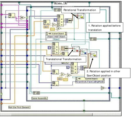
Figure 4.2. Use of rotational and translational transformation operations……….. 62
Figure 4.3. VMEs used without transformation operations………. 63
Figure 4.4. Scene resulted of rendering VME without transformations……….. 64
Figure 4.5. Applying transformations and animations on the same VME……….. 65
Figure 4.6. Using transformations operations………. 65
Figure 4.7. VMEs in correct (X, Y, Z) coordinate……….. 66
Figure 4.8. Inheritance addition……….. 66
Figure 4.9. Description and movement of mechanisms used……….. 67
Figure 4.10. Description of VME used in rendering scene………. 68
Figure 4.11. Structure needed for correct inheritance and mechanism functionality….. 69
Figure 4.12. Example of VME added as children………... 69
Figure 4.13. Main screen of the assembler……….. 72
Figure 4.14. Principal assembler menu………... 72
Figure 4.15. Select Elements option from principal assembler menu………. 73
Figure 4.16. VMEs in Assembler library any one of these can be chosen to be used… 73
Figure 4.17. Selection of some VMEs……… 74
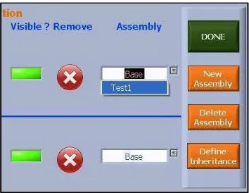
Figure 4.18. Edit Elements option from principal assembler menu……… 74
Figure 4.19. Edit Elements window controls……….. 75
Figure 4.20. Inheritance definition……….. 76
Figure 4.21. Addition of a VME in a new subassembly……….. 77
Figure 4.22. Addition of subassembly to the inheritance……… 77
Figure 4.23. Three assemblies in a inheritance tree……… 78
Figure 4.24. A more elaborated structure of inheritance tree………. 78
Figure 4.25. Assembly edition, and inheritance definition………. 79
Figure 4.26. Inheritance assembly structure for achieve the correct functionality……. 80
Figure 4.27. Build Model option chosen from Assembler principal window ………… 80
Figure 4.28. VMEs are rendered in the scene……….………… 81
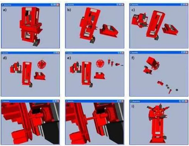
Figure 4.29. Process of placing the VMEs in their correct position……… 82
Figure 4.30. Rotation transformations added from assembler front panel……….. 82
Figure 4.31. Usage of Import and export assembler options………... 83
Figure 4.32. Save as VI a option is shown in front panel……… 83
Figure 4.33. Assembly template front panel……… 84
Figure 4.34. Assembly template block diagram...………... 84
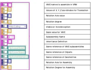
Figure 4.35. Constant cluster gotten from assembler……….. 85
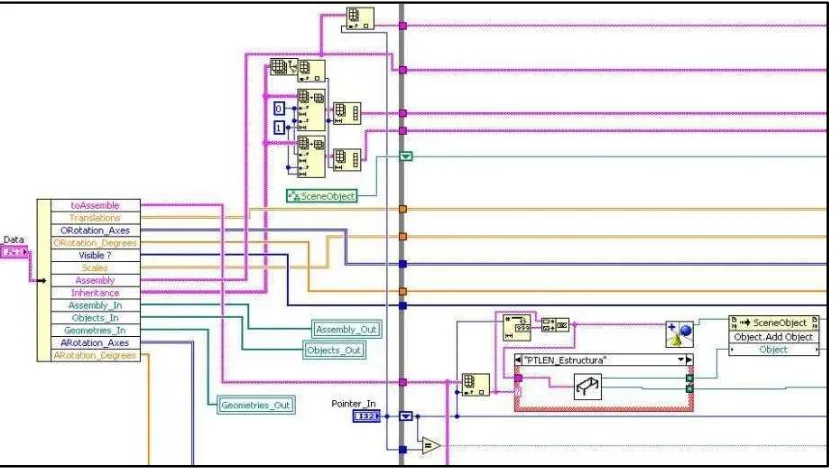
Figure 4.36. Builder VI……..………. 85
Figure 4.37. Assembler internal programming “calling VME part.”……….. 86
Figure 4.38. Assembler programming part for placing VME in correct………. 87
Figure 4.39. Assembler programming part used for inheritance definition……… 88
Figure 4.40. VMEs reference gotten and organized in arrays………. 89
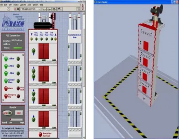
Figure 5.1. VRM Elevator front panel and VRM rendering………... 93
Figure 5.2. Name of the Signal Received from the controller………. 94
Figure 5.3. The four axes receive their conditions from the external inputs………….. 95
Figure 5.4. Transformation VI used in Animation process………. 96
Figure 5.5. Internal programming of VMM used in the VRM……… 97
Figure 5.6. VME References indexed from builder.vi……… 98
XI
Figure 5.8. VME that moves in the VMM shown………... 100
Figure 5.9. Elevator’s sensors illustration………... 101
Figure 5.10. Elevator’s touching sensors close up……….. 102
Figure 5.11. Description of the touching sensor’s sensing zone………. 103
Figure 5.12. Internal programming of Touching Sensors………... 104
Figure 5.13. LabVIEW Animation programming for touching sensors……….. 104
Figure 5.14. Interaction between VMMs and Virtual Sensors……… 105
Figure 5.15. More kind of sensors used in VRM……… 106
Figure 5.16. Organizations of signals sent for the VRM’s virtual sensors……….. 107
Figure 5.17. Programming for changing color affecting object geometry……….. 108
Figure 5.18. Tire’s rim VME appearing and disappearing……….. 109
Figure 5.19. Usage of culling SceneObject in Figure……….. 109
Figure 5.20. Communication of signals between PLC and VRM………... 111
Figure 6.1. 3 Stories Elevator pin out table………...……….. 113
Figure 6.2. Identification of signals………. 114
Figure 6.3. Names of the connection signals………... 115
Figure 6.4. Identification and addressing of PLC inputs and outputs………. 116
Figure 6.5. Extraction of the individual signals received from the controller…………. 117
Figure 6.6. Organization and structuring of signals that are send to the controller……. 118
Figure 6.7. Communication Library for interconnecting VRM with controller……….. 118
Figure 6.8. As final step a VRM Pin Out table is created………... 119
Figure 8.1. VRM Connection configuration VI……….. 122
Figure 8.2. WinLC interaction in automation network………... 123
Figure 8.3. WinLC Configuration………... 124
Figure 8.4. OSI Model description……….. 125
Figure 8.5. PROFIBUS network……….. 126
Figure 8.6. PLCSIM example ………. 127
Figure 8.7. Automation & Control Laboratory equipping proposed………... 129
Figure 8.8. Real Process Line Machine………... 130
Figure 8.9. VRM Process Line...………. 130
Figure 8.10. VRM Communication diagram………... 131
Figure 8.11. VRM controlled by PLCSIM……….. 132
Figure 8.12. VRM controlled by External PLC………... 132
Figure 8.13. Pin Out table of the VRM “Process Line”……….. 133
Figure 8.14. Description of Inputs & Outputs of the VRM machining center………… 134
Figure 8.15. Description of Inputs & Outputs of the turning table………. 134
Figure 8.16. Description of Inputs & Outputs of the pusher table……….. 135
Figure 8.17. Description of Inputs & Outputs of the conveyor 2……… 135
Figure 8.18. Description of Inputs & Outputs of the conveyor 1……… 136
Figure 8.19. Description of Inputs & Outputs of the conveyor 3……… 136
Figure 8.20. VRM’s Pusher X+ & X- Ladder logic programming………. 137
Figure 8.21. VRM’s Interaction with Students……… 138
Figure 8.22. VRM Automation education impact…...……… 139
Figure A.1. Delmia Automation application………... 153
Figure A.2. eM-PLC Communication diagram………... 154
Figure A.3. SIMIT SCE example, a 2D animation is controlled with PLCSIM………. 156
Figure A.5. 2D Tank simulation created in Unity Pro……….……… 158
Figure A.6. Tank simulation Unity Pro creation……….……… 158
Figure A.7. EasyPort interface for connecting EasyVeep with PLC.……….. 160
Figure A.8. EasyPort interface for connecting EasyVeep with PLC.……….. 160
Figure A.9. Processing Station available in Cosimir PLC………….………. 161
Figure A.10. Wonderware InControl example………….………... 162
Figure A.11. Transport Band created in InTouch……….………... 163
Figure A.12. Tarakos Software scene representation……….. 164
Figure A.13. Combination of I/O cards for controlling external devices……… 164
Figure A.14. Machines included in EasyPLC demo version built with the machine….. 166
Figure A.15. Virtual Plants built in SPS-VIS….……….……… 167
Figure A.16. Exercise created in ProSIM-II……… 168
Figure B.1. 3D Picture Control Pallet Geometries……….. 173
Figure B.2. Geometry cone rendered in LabVIEW………. 173
Figure B.3. Geometry cylinder rendered in LabVIEW……….. 174
Figure B.4. Geometry box rendered in LabVIEW……….. 174
Figure B.5. Geometry sphere rendered in LabVIEW……….. 175
Figure B.6. Text added to Box Geometry………... 175
Figure B.7. a) Image in 2D, b) 3D high field gotten from 2D image……….. 176
Figure B.8. Blue pentagon created using Mesh………... 177
Figure B.9. Draw mode options for mesh………... 178
Figure B.10. Points option for drawing Scene Mesh……….. 178
Figure B.11. Lines option Drawing. ………...……… 178
Figure B.12. Line strip option drawing………... 178
Figure B.13. Mesh gotten with lines strip option drawing……….. 179
Figure B.14. Lines loop option drawing……….. 179
Figure B.15. Mesh gotten with lines loop option drawing……….. 179
Figure B.16. Triangles option drawing……… 180
Figure B.17. Mesh gotten with triangles option drawing……… 180
Figure B.18. Triangles strip option drawing……… 180
Figure B.19. Mesh gotten with triangles strip option drawing……… 181
Figure B.20. Triangles fan option drawing……….. 181
Figure B.21. Mesh gotten with triangles fan option drawing……….. 181
Figure B.22. Quads option drawing………. 182
Figure B.23. Mesh gotten with Quads option drawing……… 182
Figure B.24. Quads strip option drawing……… 182
Figure B.25. Mesh gotten with Quads strip option drawing………... 182
Figure B.26. Polygon option drawing………. 183
Figure B.27. Mesh gotten with Polygon option drawing……… 183
Figure B.28. X, Y, Z Vertex array cluster………... 183
Figure B.29. Index array……….. 183
Figure B.30. RGBA color array cluster………... 184
Figure B.31. Color mode………. 184
Figure B.32. Color applied with Binding Off option……….………. 185
Figure B.33. Normal Array……….. 185
Figure B.34. Normal mode……….. 186
XIII
LIST OF TABLES
Table 1. Principal Features of Automation Simulation tools in market……….. 14
Table 3.1. VRML Design Constraints………. 33
Table 3.2. VRML file section descriptions……….. 52
Table 4.1. Assembler Advantages………... 90
Table 4.2. Assembler Disadvantages………... 80
Table 9.1. Principal Features of final applications including VRM……… 141
Table 9.2. VRM Advantages and disadvantages………. 142
Table A.1. Principal Features of Automation Simulation tools in market……….. 171
CHAPTER 1
Introduction
The consumption world market is constantly increasing its requirements. Day by
day, better quality products are asked by customers that shrink product life cycles, increase
product variant and reduce product launch times. Moreover this happens while market
prices erode. These requirements by dynamic customer represent challenges that
manufacturers have had to face in a highly competitive environment. New requirements
force companies, either globally or locally, to implement technologies, processes, and
practices that enhance their competiveness, increase their profit, give them arguments to
compete, make them more efficient, position their products as the clients’ favorites and
differentiate them from the others.
Some of the practices that companies implement daily with the purpose of
increasing their competitiveness advantages are product improvement, constant change of
product offer, process standardization, price reduction, flexible process, optimization
process, quality programs, etc. However, some of these practices appear to be opposing; on
one hand, a fresh product offering requires constant changes in the production lines to
reduce costs as opposed to the standardization process. To remain successful in the market
and even to survive, companies must be able to innovate constantly. Innovation must be
oriented to look for the necessary practices and tools that help the company face these
challenges and assure that the changes made in any production matter to improve some
sector in the company impacts is carried out in a planned way.
On the other hand, the globalized market has forced companies to focus their
production on scale economies in order to offer their products around the world increasing
its production. Higher production quotes have motivated that companies open new plants
around the world, increase their production lines and change or totally replace their
processes and the way they manufacture goods. This growth has brought a bigger
organization structure inside companies and more processes to control and manage. In
addition, companies have adopted practices like lean manufacturing, Six Sigma, QFD, ISO
quality certifications and other quality production activities required for markets or added
to manufacturers’ standards. These new challenges demand from companies to handle more
specifications for products and more information about processes and procedures.
2
as Digital Manufacturing tools (DM) which merge the virtual and the physical
manufacturing worlds.
Digital Manufacturing (DM).
Digital Manufacturing is an integrated suite of software solutions that supports
manufacturing process design, tool design, and visualization through powerful 3D virtual
simulation tools
1. These tools allow the manufacturing engineer to validate and optimize
the manufacturing processes through visualization: design, synchronization and validation
of production lines, robotic work cells, machine centers, production equipment, control
systems functionality and requirements. All these functions are completely carried out
before purchasing, installing, and commissioning the physical equipment. In essence,
Digital Manufacturing facilitates the complete view of the product and the process design
as integral components of the overall product life-cycle and enables product design
methods to be not only sensitive to process constraints and capabilities, but, in fact, be
completely integrated with the manufacturing processes.
Applications developed in DM tools make it possible for the manufacturing
engineer to design and virtually simulate exact models of machines, robots, conveyor lines,
work cells, and practically any production equipment. These models are usually required to
fabricate, assemble, and install parts, sub-assemblies, and components of the product. The
factory environment of the production process can also be modeled including buildings,
production lines, transportation, workflow, and other facilities that represent the complete
physical production environment.
The immediate effects and benefits for manufacturers that use DM tools are as
follows: a substantial reduction of the manufacturing lifecycle in regards to product launch
time, assurance of production changes impact, testing of different production scenarios and
significant cost savings
1. All this is done by the virtual validation and commissioning of the
production systems. Virtual validation and commissioning have become more important
lately since the demand for larger production and trustworthy processes have transformed
the machinery used for production. Machinery transformation is oriented to the automation
of complex manufacturing systems, replacing traditional assembly processes. Due to this,
DM allows manufacturing engineers to merge virtual models of production equipment with
automation and control. DM enables the complete validation of the control logic,
automation strategies and HMI functionality in the Automation Simulation process. This
DM extended level of manufacturing process design and execution capability helps
manufacturers vie in an intensely competitive, global environment
1. DM enables companies
to execute “flawless” launches, execute production changes by totally validating all matters
concerned with the process from the tool to machine design to the final automation
strategy.
Automation Simulation.
manufacturers need larger production quotas which translate in an increase of machinery
usage time. Nowadays, it is very common that manufacturing cells work 24 hours per day
trying to meet production quotas. High competition in the market and higher production
quotas have motivated that day by day traditional manufacturing processes be replaced
more frequently by complete automated systems. The usage of automated systems reduces
human errors, carries more advanced task out, increases processes accuracy and production
output and has hardware and software specially designed for working non-stop, long laps.
The largest manufacturing companies that first introduced this trend in production
automation systems were those in the automotive sector, such as General Motors Chrysler
(GMC), Volkswagen, and Ford. Today their production lines are mainly conformed by
automated machinery and sets of robots that work totally synchronized with conveyors,
presses, furnaces, CNC machines, etc. This complete automation production system is
integrated to other management production systems to receive feedback and production
information
2. This trend in automation is supported by software and hardware. Constant
technology advances in robotics and the automation field have made it possible to have
production automation available for medium and small manufacturing companies too.
The present automated systems go from the simplest to the most complex. Some of
them can be formed by single-process automated manufacturing cells as a basis. A set of
these are grouped in automated production lines which at the same time are grouped in
production systems. These systems can be made up only by machines or may include an
individual or a set of industrial robots requiring a minimum or no human interaction when
working. These are controlled by autonomous programmable controllers that handle
electrical process inputs and outputs and implement the necessary logic and calculus to
control them. From the variety of automated industrial processes, even single automated
manufacturing cells require automation and the implementation of a control strategy. The
complexity of process automation depends on the process. For example, automation
complexity increases in automated production lines and is even more complex in automated
production systems that commonly require complete network architecture of control
devices. In these networks, control devices communicate with each other receiving process
signals that come in from machine sensors and send out signals to machine actuators that
are part of the process. In addition, communication signals with high or low level
controllers inside the network are also received and sent out. Then, despite these, automated
systems require a minimum of human interaction when working. During initial
commissioning, the sending and receiving of communication data, the recognition of
sensors signals and the sending of signals to actuators when the process is being automated
have to be programmed in control devices. In addition, when failure or process variation –
such as product change, addition or replacement of machines, changes in automation
hardware, software upgrades, etc. occurs, it is also necessary to change the programmed
automation logic. Human interaction is thus needed for these tasks since the programming
is done by control and automation engineers or by staff with special training,
knowledgeable of the process, the control hardware and the programming software.
4
requirements, for instance: that the optimized control program causes no accidents, that the
launching time and deadline for implementation are the shortest and do not affect
production, and even more important, that the production system works correctly regardless
of how easy or difficult the control program handling the production changes is.
Automation is supported by an extended variety of autonomous programmable
controllers available in the market. PC-Based controllers, microcontrollers,
microprocessors, programmable automation controllers (PAC), programmable logic
controllers (PLC) are present. From these, PLCs have the major presence in the industry
because of their roughness and wide variety of hardware configurations and brands in the
market. PLCs may be used in small and simple or large and complex production systems.
Many of them have the capability of network interconnection. The constant usage of PLC
in the manufacturing sector has motivated further advances in the PLC hardware and
software communication. For example, the addition of Industrial Ethernet and the adoption
of OPC has become a standard of data communication between control devices from
different manufacturers. Communication advances have made it possible that PLCs from
different brands communicate with each other or with Personal Computers (PC), situation
that years ago was impossible due to the way brands handled their communication
protocols. These advances have fostered the evolution of PLCs, from those used in a single
process as the implementation of a standalone to becoming a part of an industrial network
in which information is shared among control devices from different brands.
With the growth of automated production systems, manufacturing companies have
the need to assure the changes in the production systems by validating that the control
automation hardware and control system strategies implemented on these work correctly
and are in accordance to standards. This need, along with communication with PLCs and
interconnection capability with PCs and other computing devices motivated the
development of a segment inside Digital Manufacturing tools, the automated simulation,
which focuses on covering and solving manufacturing needs.
provides manufacturing and control engineers an opportunity to ensure the control design
before production starts.
Virtual Commissioning.
Virtual commissioning is state-of-the-art technology on digital manufacturing
simulation. It is based on advanced simulation methods which truly represent the merging
of 3D virtual simulation environments with the physical automation world of control logic
and control platforms to accomplish the required level of automation and synchronization.
This is carried out on virtual prototypes of production systems and equipment which are
based on the capabilities and appearance of a real model. Virtual Commissioning was
originally intended to allow the debugging of the control code on an actual Programmable
Logic Controller (PLC) that would be on the shop floor, weeks or months before the
integration of all the devices. These devices could be tooling, robots, clamps, safety
devices, electrical, hydraulics and pneumatics components. However, the virtual
commissioning scope goes beyond; it has turned itself into an important business enabler.
Ideally, it allows the user to optimize and validate costs efficiently and effectively; and
validate any implementation or change of strategies in the manufacturing process controls.
Virtual commissioning makes it possible to test different control scenarios, to accelerate the
learning curve and to enable control engineers to reduce the occurrence of costly errors,
mitigating the risks in a virtual environment well before using real equipment to
accomplish commissioning
3.
Automation simulation is a DM tool based on virtual commissioning. Its principal
objective is to serve manufacturers as a tool to enhance their competitive advantages in the
global market. Moreover, in addition to virtual commissioning, the feature of
experimenting different control strategies in virtual production environments without the
risk of costly errors has caused that automation simulation is also used for training
purposes; beginning control engineers who will be responsible for programming control
logic process strategy in specific machinery, work cells or production lines can be trained.
When the virtual commissioning occurs, learning can take place on virtual environments
without the risk of damaging the equipment physically. Additionally, more experiment
control engineers can be trained, especially when new machinery or new automation
equipment will be used.
6
Virtual commissioning is intended to validate control strategies on virtual
production system environments, and then to move these to the real production system.
However, this movement is not extremely necessary since the validation of control strategy
can be done anyway even if the virtual commissioning stops in the virtual environment. In
other words, if real machinery will not be used, the automation simulation is useful to
validate the programming of the control engineers as the necessary knowledge to control
the virtual production system, just as the real one
3. This is similar to the training of industry
control engineers, but it has a different orientation. Thus, automation simulation can be
used with didactic objectives not only to train someone to use specific machinery but also
as a teaching tool in automation and control courses. The virtual environments developed
on automation simulation tools offer a control process in which students can observe the
right or wrong functioning of their control program. This way, automation simulation
supported by virtual commissioning is used in the industry and for educational purposes. In
the former it has two orientations: the optimization and validation of production systems,
and the training of control engineers and workers. In the latter, it is used in control and
automation courses in which final applications are used to support the education and
practice of engineering school students.
Automation Simulation for Optimization and Validation.
With PLM tools, manufacturing engineers are able to create a virtual manufacturing
environment through powerful simulation applications. On this environment, they can
develop and design products, plant layouts, production lines, work cells, material work
flow, automation designs, and any production process. When the virtual environment that
represents the plant is created, engineers are able to generate process plans, work steps,
assembly definition and sequencing, and tool design. They can even generate a control
code. Then, PLM makes it possible to deliver a product design that allows
manufacturability. This is done by simulating the manufacturing processes of virtual
products on virtual production environments early in the product design process. This
capability allows a better product design while optimizing the production process.
For manufacturing companies, the amount of time it takes to deploy, install, and
commission new production lines for general assembly, painting, stamping, body-in-white,
and other assembly systems, and to bring all these systems up to the production stage is
much extended. Not only do new lines require time for starting up, but also the production
lines or product changes need time for planning, execution, and validation. Changes in
working production lines are more critical because these impact directly in the production
ratio of the factory. Since the goal is to reduce the cost for launching new models, both time
and resources have to be controlled while still satisfying the requirements of the production
lines and the delivery of the new products on schedule. To assure these critical factors with
the PLM tools, manufacturing companies are using automation simulation technology more
often.
control strategy and an automation program that can be loaded to real automation hardware
controlling the real production systems. Additionally, it links the actual production work
environment through the connection with the machine control systems. One thing is
modeling and simulating the machine tool, the conveyor line, the robotic work cell, and the
pneumatics and hydraulics systems, but quite another is generating accurate information
capable of running the control systems correctly for all the production equipment.
Automation simulation gives production operations engineers the capability to build
virtual production systems based on real automation events
2. It also makes it feasible for
engineers to virtually model conveyors, workstations, and controls as well as the right
physical and logical interface and material handling operations that can occur between the
components of work cells and production lines. An important feature is that it permits the
development of control strategies or the construction of production scenarios for
experimentation that would otherwise be expensive and/or time-consuming. This empowers
engineers to try ideas in a dynamic, synthetic environment while collecting virtual response
data to determine the physical responses of the control system. This feature, in addition to
validation, provides a collaborative workspace for mechanical design, manufacturing, and
control engineers to share knowledge, exchange system features and attributes, integrate
process information, and react to engineering changes and version updates. The
collaborative work around a virtual model shortens the ramp-up of production lines during
commissioning and product launch, as well as the designing/building process, cost, time,
design changes, and risk of errors. All this facility aspects represent critical factors in
product delivery and, ultimately, a company’s profit or loss. These capabilities have made
of automation simulation a key piece for the manufacturing industry since manufacturers
have validated the plant’s control systems before production starts
4.
Engineers typically find over 100 mechanical and electrical errors in logic, HMI,
and drawings per cell
2. Two to three man weeks are saved during startup, saving thousands
of dollars in engineering and production labor costs. Problems are normally found and fixed
with minimal disruption to operations. Problems found in the field are solved more quickly
since engineers can narrow them down to items such as physical connections, confident that
the validated control code works. Scenarios not expected during startup can be simulated
and corrected beforehand. All faulty conditions of the process can be tested, and all HMI
interfaces will perform as expected at startup and workers will be familiarized with these
provided they were previously trained on virtual models.
8
companies. Manufacturers producing models in large scale can also benefit of this software
technology, which will be explained next.
Automation Simulation Advantage for the Industry.
Pre-validation of control and production systems before production starts
.
It is
possible to validate electrical and mechanical features in the engineering design phase,
enabling acceleration of production. In addition, since the production system starts out
working as it is supposed to, the product’s initial quality is improved.
Debug time minimized at the plant
. Almost all electrical and mechanical designs can
be validated by virtual commissioning; then most of the validation left to do at the plant is
narrowed down to checking physical connections and software interfaces. This leads to
significant reduction in production launch work force at the plant, engineering, direct labor,
and travel costs of experts.
Validation of production commissioning on a virtual environment.
Evaluating PLC
program changes on the virtual model instead of taking risks on the real equipment
minimizes production risks by simulating several manufacturing scenarios and allows
validation of mechanical and electrical components to be integrated in the production
processes (PLC and robotics).
Visualization and optimization of the process functionality and behavior.
Processes
can be run by the PLC code prior to integrating them to the production engineering phase.
This increases the speed, consistency and reliability of design processes, achieving a
significant reduction in risk and start-up time since it is possible to detect logic errors well
before ramping-up.
Testing of conditions before production starts
.
Automation simulation enables
engineers to iterate quickly through practically any scenario validating as many “what ifs”
as needed and fully debug the control test production and failure conditions. In addition,
validation of all diagnostic codes can be done away from the shop floor.
Standardization of validation processes to be used globally.
An automation
simulation capability helps reinforce common validation processes throughout the
company. This allows mechanical design and control departments to work concurrently by
sharing manufacturing information and proving the feasibility of the production cell and its
time cycle.
Automation simulation in Training.
In training for engineers, usually control or manufacturing ones, automation
simulation is used to build virtual environments emulating real production systems that are
or will be present on the shop floor. The objective of these training simulators is to serve as
a virtual commissioning tool with which engineers gain a proper understanding of the
process, test control strategies, observe production systems limitations and scopes, know
production times, respond to process changes, learn how the system behaves when a
strange condition is present, and know what to do to solve any malfunction. These aspects
are principally important for beginning engineers or for new ones in a specific area within
the company. Since the virtual environment represents the future production systems in the
shop floor or the changes taking place at present, training with automation simulation tools
is also useful for experienced engineers unfamiliar with the new production system. Then,
once that the virtual environment is built, the training for engineers consists of consecutive
virtual commissioning on the same virtual simulation of the production system. This is
done for them to get the necessary knowledge from the simulation to understand and
control the production systems in the future. Virtual environment built with automation
simulation tools can even make it possible that engineers automate more complex systems
than those that they have in the shop floor, increasing their expertise and automation
knowledge. This can be done because it is not necessary to have the real production system
to carry out the automation. Traditionally, this training could have meant a large economic
investment of the companies, an expenditure that is not paid with virtual environments
developed with automation simulation tools. The availability of these simulators and other
virtual commissioning tools are of invaluable help to manufacturing companies throughout
the lifecycle of the plant.
Training for workers also uses virtual environments created by automation
simulation tools of virtual commissioning. Yet, these emulations are not intended for
constant virtual commissioning. This means that control strategies are not validated on
these
3. The objective is to use a simulation to train workers previously developed and
commissioned by control engineers. This is important since workers constantly operate the
machines and use the real production systems on the shop floor. The workers in
manufacturing companies receive training when they are hired, when they are moved to a
different production process, when new machinery will be used or when a product change
has been planned.
10
plant to go on operation and the learning curve of its workers. It minimizes the risks as it
enables the plant operators to perform the tasks needed by their manufacturing employers.
The training can be accomplished with a deep understanding of the functioning and
operation of the machine the worker will use. In addition, some of the training data are
augmented with recorded narrations and videos that explain the key points of the machine.
With the level of practice that can be achieved with virtual environments, workers can more
easily absorb the information both visually and aurally.
Automation Simulation in Education.
Automation simulation software tools are used with two orientations in education.
The first one is their usage principally in universities focusing on control, automation,
mechanical, manufacturing and electrical programs. In universities, automation simulation
tools are taught principally in advanced engineering courses where students learn about the
automation tool itself, its features, limitations, scope, etc. Students work with the
development environment and not with final emulations. This is because the teaching is
oriented to the automation simulation tool as it is used in the industry and it also requires
engineers working with these tools. The most popular automation simulation tools in
education are Delmia by Dassault Systemes, Tecnomatix by SIEMENS and Festo. These
developing tools are usually expensive and unaffordable for many universities, mainly in
those of developing countries.
The second automation simulation orientation consists in using a final emulation
application to teach engineering students and to support the automation and control theory
taught in classrooms and is later practiced in laboratories. On these virtual environments, a
student’s control and automation strategies can be tested in the emulation of real production
systems, without the risk of damaging costly equipment. This is done taking advantage of
the automation simulation objective of validating, optimizing and testing control and
automation strategies in virtual environments. Then, these are deployed in the real
production systems equipment. It is also possible to carry out all the automation
commissioning process, and never deploy the automation control strategies in a real model,
just as the training is done with engineers in the industry.
complement and support their automation and control courses, and to increase their
students’ knowledge and abilities.
On the other hand, the market has a limited offer of final virtual applications. There
are only a reduced number of companies such as Festo by Ciros Mechatronics, SIEMENS
by SIMIT SCE and EasyPLC that offer 3D final applications to carry out virtual
commissioning and learning automation. Prologix, an independent tool, offers 2D final
virtual applications; others, such as Delmia Automation by Dassault Systemes, Tecnomatix
by SIEMENS, RSTestStand by Rockwell and Unity Pro by Schneider are oriented to
provide the software tool to build virtual applications and not to offer final virtual
environments with which students can test and validate their programs. Then, from the
reduced number of vendors in the market, there is even a more reduced group that offers
final applications for training serving educational institutions whose scope varies.
Application particularities have advantages and disadvantages between final virtual
applications that impact directly in the students’ learning level. Although the strong impact
that these final applications can have in education, these have not been broadly used since
they are not as popular in education as they could be. Considering their scope in training,
the lack of popularity has been motivated mainly for the particular disadvantages in the
tools and the small number of options in the market.
1.1 Automation Simulation Software Tools in the Market.
Automation simulation is practically new and has been exploded and developed
only by a reduced group of software vendors. The software solutions present in the market
are very different; each with its own particularities and scope
4. The differences found
concern mainly to matters such as origin, target sector orientation, cost, country of origin,
visualization capabilities, supported connectivity, licensing, complexity in usage, level of
integration level, programming environment, performance, flexibility, quality of graphs,
etc. The origin of the tools available in the market varies since different companies
orientated to sectors related to manufacturing and automation have created these tools;
other have been developed by a small group of individual programmers seeking specific
purposes. The origin seems to be closely related to tool particularities and scope. Some
aspects of the software tool developing company – such as expertise, know-how, objective,
availability of means of previous software developments, product portfolio, etc.- dictate
some of the main features of the tool and therefore its scope. The origin of the tools refers
to the orientation of the company that created or commercializes the software tool. There
are three main origins of the tools present in the market: 1) PLM software tools; 2)
Automation hardware and/or software vendors; and 3) Software tools from a third party.
PLM software tools.
12
automation simulation tools within their product portfolio: Delmia from Dassault Systems
powered by IBM and Tecnomatix powered by SIEMENS. From these two with previous
experience in CAD/CAM and CAP software, Delmia is the pioneer of this technology and
is the one to establish and define the automation simulation and virtual commissioning
concepts. Delmia Automation is the tool offered by this vendor. Tecnomatix is more recent
and arises from the integration of Unigraphics with SIEMENS; it offers a tool called
eM-PLC oriented to virtual commissioning with SIEMENS´s eM-PLCs
5.
Automation Hardware or Software Vendors.
Automation tools that have been developed and are offered in the market by
automation hardware manufacturers are part of this classification. Automation technology
software is closely related to and necessary for using automation hardware. Companies that
are vendors of automation hardware such as SIEMENS, Rockwell, Schneider, ABB, etc.
offer in their product portfolio different software applications oriented principally to own
PLC programming and PLC emulation. Some of these also offer automation simulation
software intended to develop virtual emulation software. The resulting applications vary in
visualization, scope and complexity depending on the vendor. Visualization of these tools
goes from primitive 2D objects to the import of 3D solids created in CAD; the scope of
these tools is mainly oriented to validate PLC programming. Despite of the facts that these
tools do not offer the features and capabilities that PLM tools offer and that they have a
reduced scope, their principal objective is to validate automation and control PLC
programming, which are considered automation simulation tools
4. The most important
feature of this kind is that it is only compatible with the developer’s automation hardware.
SIMIT by SIEMENS, RSTestStand by Allen Bradley and Unity Pro by Schneider are
examples of these.
Software Tools from a Third Party.
are the most commonly used, and they cover most of the tools present in the market. In case
of any omission, the mentioned tools describe well the status and the simulation capabilities
of the tools in the market.
14
1.2 Objectives.
Propose the development of a general procedure of 6 stages (3D CAD creation, Conversion process, Assembly process, Animation process and VRM Validation process) followed for the creation of an automation simulation virtual final application called VRM (Virtual Reality Machine) oriented to automation and control training by it usage for automation and control laboratory equipping. Whose features of performance and free licensing make possible that VRM can be applied to education. Where can contribute to student’s formation and can be adopted even for low resource educational institutions.
Introduce the development and usage of two software tools that reduce the VRM development time called: “VRML to VME Converter” which turns 3D solids drawn in CAD in LabVIEW VIs (Virtual Instruments) and “Assembler” which places LabVIEW 3D objects in their correct spatial position. These tools make more efficiently respectively the stages of Conversion process and Assembly process from the “general VRM creation procedure”.
Propose an equipping solution for automation laboratories taking as example one station of the Automation Networks Laboratory at Instituto Tecnológico y de Estudios Superiores de Monterrey (ITESM) Campus Monterrey, where the VRM concept already is being used for supporting training in automation, industrial networks and Human Machine Interface (HMI) development.
1.3 Justification.
The market requirements have pushed companies to implement practices that foster their competitive advantages. Within these practices, one that companies commonly use is cost reduction in all possible sectors companywide. Companies look for work force in developing countries where labor is cheaper as a common practice of cost reduction. Companies move or open new factories in those countries with the objective of increasing their profit by work force cost reduction. When a company moves operations to a developing country, it looks principally for two kinds of workers in the manufacturing area: laborers that do routinely work and engineers that do more complex and higher added value work. Companies easily find laborers in developing countries, but they do face a problem finding qualified workers for higher added value activities. The lack of human resources for these activities causes that these be done by people that come from the company´s home country or from developed countries. This results in a vacancy, a reduction of salary level, and a high level of unemployment for professional people from those countries.
16
the market for this purpose are expensive and some public universities lack the necessary funds to buy manufacturing cells, robots, conveyor systems, machinery, etc. for the automation practice to take place. This restriction is not exclusive of low budget universities. Even for universities with funds, the purchasing of updated equipment similar to the one used in the industry or purchasing enough equipment for the whole student population is barely possible for some of them.
The lack of equipment is most common and drastic in Latin America, Africa or the Middle East universities. Instead, these universities have to build their own training stations or buy old equipment for students practice. In addition it is common that the amount of equipment bought or the equipment in laboratory is insufficient for the students enrolled in the class or its usage is restricted or oriented to observation purposes. This particularity of laboratories infrastructure has caused that many universities lacking resources avoid offering expensive undergraduate or graduate programs or offer automation or manufacturing engineering programs where the laboratory practice has been excluded. When this is the case, automation and control courses are only supported by the theory taught by the professor in the classroom; therefore, students are unable to develop the necessary abilities and skills, causing a gap in the students’ formation.
It is costly to give students training on the plant, work cells, use of robots, their control and automation. Only some universities count with a reduced number of real or close-to-real processes for practicing purposes. Therefore, universities in developing countries try to resolve the problems in the automation field with traditional methods, such as in the usage of a set of leads and buttons connected to the controller’s inputs and outputs. These leads usually blink when one button is pushed. The blinking of the leads indicates the action of one signal sent by the program. This practice is also common in course of microcontrollers for which the traditional traffic lights of red, yellow, and green leads are still used. There are other homemade testing stations with which students have to imagine that leads, motors, relays, pistons or valves are put to work and have certain functionality. In the best of the cases primitive structures such as elevators and mixers are built for students to test their control programs. Homemade systems are better than nothing for student’s practice. These are not the best solutions for students to learn since the equipment used in laboratories has to be similar or at least mimic the one used in the industry. Different brands for training stations are available in the market. These stations mimic processes using LEGO type elements and use little dc motors, wiring, and plastic or metal structures. Still, as aforementioned, the cost of these stations is high and can barely be paid by many universities.
carried out, how programming relates mechanisms or networks, how devices are controlled and how the interaction of the process with one controller is needed. The end result is that this problem does not only affect universities, but it also affects the companies that hire technicians, educated in technical schools which offers technical programs related to automation and manufacturing. Technical schools have a more limited budget than universities, so their laboratories –if any- are less equipped. Therefore, students sometimes graduate without having programmed a PLC or without experience.
This lack of training during the educational process has encouraged the situation that some companies compare an engineer from a developing country with a technician from a developed one. Therefore, the growth of an engineer within a company is limited. Above all, most of the job openings offered by a company are to hire workers, and the more advanced fabrication processes are still carried out in developed countries due to the lack of qualified engineers in a developing one. The lack of formation in engineers from developing countries and that engineers are only followers of instructions since they fall short in the knowledge of the system that they operate has caused that developing countries do not produce their own technology. Although engineers have access to the technology of advanced countries in industrial plants, they are unfamiliar with the technology and its functionality.
Other aspect to consider is the increasing trend in companies of using industrial robots in a wider variety of processes. From a rough point of view, this trend is closely related to the replacement of workers for industrial robots. This replacement has mainly been done in tasks that require dangerous or routinely work with the objective of reducing costs and increasing safety, reliability, production, profit, quality and number of products. Robots can work continuously until maintenance or other issues happen. Another aspect favoring the use of robots is that have no demands concerning the comfort of their environment, require no rest and need no time for lunch. The combination of robots and automation systems is an aspect that can refrain some manufacturers from moving to developing countries looking for cheap work force. It makes no sense to move production to a developing country looking for cheap labor if they can use robots in their home countries. Besides, in developing countries they will find no personnel capable of programming, fixing, maintaining or doing high technology activities in robots or automated lines.
The present situation is determinant for developing countries whose manufacturing sector is a key factor in their trade balance and is one of the most important sources of employment. The formation of engineers and technicians takes place in educational institutions in these countries.