Control contributions to the universal operation of wind turbines
177
0
0
Texto completo
(2)
(3) DEPARTAMENTO DE ELECTRÓNICA. Edificio Politécnico Campus Universitario s/n 28805 Alcalá de Henares (Madrid) Teléfono: 91 885 65 40 Fax: 91 885 65 91 [email protected] [email protected]. UNIVERSIDAD DE ALCALÁ, PATRIMONIO DE LA HUMANIDAD. Dr. Emilio José Bueno Peña, Profesor Titular de la Universidad de Alcalá, y Dr. Francisco Javier Rodríguez Sánchez, Profesor Catedrático de la Universidad Alcalá,. INFORMAN:. Que la Tesis Doctoral titulada “Control Contributions to the Universal Operation of Wind Turbines” presentada por D. Mario Rizo Morente, y realizada bajo la dirección de los doctores D. Emilio José Bueno Peña, D. Marco Liserre y D. Francisco Javier Rodríguez Sánchez,, dentro del campo de la aplicación de los VSCs como interfaces entre la red eléctrica y sistemas de generación de energía eléctrica, reúne los méritos de calidad y originalidad para optar al Grado de Doctor.. Alcalá de Henares, 09 de Septiembre de 2013. Fdo. Emilio José Bueno Peña. Fdo. Francisco Javier Rodríguez Sánchez.
(4)
(5) DEPARTAMENTO DE ELECTRÓNICA. Edificio Politécnico Campus Universitario s/n 28805 Alcalá de Henares (Madrid) Teléfono: 91 885 65 40 Fax: 91 885 65 91 [email protected] [email protected]. UNIVERSIDAD DE ALCALÁ, PATRIMONIO DE LA HUMANIDAD. Dr. Marco Liserre, Profesor asociado del Politecnico di Bari.. INFORMA:. Que la Tesis Doctoral titulada “Control Contributions to the Universal Operation of Wind Turbines” presentada por D. Mario Rizo Morente, y realizada bajo la dirección de los doctores D. Emilio José Bueno Peña, D. Marco Liserre y D. Francisco Javier Rodríguez Sánchez, dentro del campo de la aplicación de los VSCs como interfaces entre la red eléctrica y sistemas de generación de energía eléctrica, reúne los méritos de calidad y originalidad para optar al Grado de Doctor.. Bari, 06 de Septiembre de 2013. Fdo. Marco Liserre.
(6)
(7) DEPARTAMENTO DE ELECTRÓNICA. Edificio Politécnico Campus Universitario s/n 28805 Alcalá de Henares (Madrid) Teléfono: 91 885 65 40 Fax: 91 885 65 91 [email protected] [email protected]. UNIVERSIDAD DE ALCALÁ, PATRIMONIO DE LA HUMANIDAD. Dr. Sira Elena Palazuelos Cagigas, Director del Departamento de Electrónica de la Universidad de Alcalá,. INFORMA:. Que la Tesis Doctoral titulada “Control Contributions to the Universal Operation of Wind Turbines” presentada por D. Mario Rizo Morente, y dirigida por los doctores D. Emilio José Bueno Peña, D. Marco Liserre y D. Francisco Javier Rodríguez Sánchez, cumple con todos los requisitos científicos y metodológicos, para ser defendida ante un Tribunal, según lo indicado por la Comisión Académica del Programa de Doctorado.. Alcalá de Henares, 03 de Septiembre de 2013. Fdo. Sira Elena Palazuelos Cagigas.
(8)
(9) ABSTRACT The continuously growth of the energy consumption is taking the current electric system close to certain limits where the power supply reliability is seriously affected by voltage interruptions. Besides, some factors like the downturn in the economy and the drive of developing countries (i.e. China and India) have forced the companies to extend their products to weaker power systems, where the power quality has not been treated with a strong regulation yet. This Thesis is framed in the improvement of the power supply reliability through the isolated operation of Wind Turbines. The concept of Universal Operation addresses the island operation of Wind Turbines when the connection to the grid is not longer required after a voltage interruption. In constrast with other tendencies, the peculiarity resides on avoiding the use of expensive external storage devices. This concept is just proposed in the low and medium power level scenarios of on-shore Wind Turbine to face power interruptions of minutes. With the general objective of extending the island operation to cover the most of the interruption, this work approaches the main challenges of the Universal Operation from the control point of view: regulation of the island power mismatch by means of the inherent storage and dissipation capacities, transition between the island and grid-connected modes, power sharing, etc. On the other hand, an important research line of this Thesis is focused on the optimization of the system response under unbalanced conditions. The proposed control enhancements deal with the oscillating power and the distortion of control references caused by unbalanced conditions.. i.
(10)
(11) RESUMEN Ante la creciente dependencia energética de los países de la Unión Europea y los informes de contaminación atmosférica, la generación distribuida mediante energías renovables está modificando el sistema eléctrico actualmente basado en el paradigma centralizado. Dentro de las energías renovables con mayor impacto actual se encuentra la energía eólica. Un aspecto importante a mejorar en el marco de la calidad de potencia por parte del operador de la red de transmisión, es la continuidad del suministro. En estas circunstancias se define el concepto de microgrid como un sistema compuesto de al menos una fuente de generación distribuida asociada a cargas locales que pueden intencionalmente desconectarse del sistema de distribución con el objetivo de mejorar la fiabilidad del suministro. Este trabajo introduce la Operación Universal de aerogeneradores, donde éstos pueden trabajar conectados a red eléctrica y desconectarse de ella cuando ocurre un hueco o interrupción del suministro operando en modo isla. Es una aplicación específica del concepto de microgrid a aerogeneradores que evita el uso de sistemas de almacenamiento empleando únicamente las capacidades de almacenamiento y disipación intrínsecas de los aerogeneradores y se centra en contrarrestar interrupciones del suministro eléctrico del orden de unidades de minutos. Este trabajo se centra en abordar la problemática asociada a la Operación Universal de aerogeneradores desde el punto de vista del control de los convertidores de potencia: regulación del balance energético, compartición de la carga y control de la tensión local en modo isla y transiciones suaves entre modos de operación. Además, el sistema debe seguir manteniendo un rendimiento óptimo en modo conectado a red respetando los códigos de red: respuesta en potencia, calidad de potencia y respuesta ante perturbaciones.. iii.
(12)
(13) AGRADECIEMIENTOS El resultado de estos cuatro años se debe en gran parte al apoyo y ayuda de todas las personas que se encuentran a mí alrededor. Estas líneas son solo una pequeña muestra de mi gratitud hacia ellos. Aunque suene a tópico, el final se ha hecho agotador y espero no olvidarme de nadie, si es así, gracias a tí también. En primer lugar, quisiera mostrar mi más sentido agradecimiento a mi director principal, el Dr. Emilio José Bueno Peña, gracias por darme brindarme esta oportunidad, por haberme guiado y aconsejado, por apostar por mi, y sobretodo, por hacerme descubrir algo con lo que realmente disfruto. El segundo lugar está reservado para el Dr. Marco Liserre. Sin duda alguna, él tiene gran parte de culpa del rumbo que ha tomado esta tesis. Muchas gracias por orientar mi trabajo durante mi estancia en Bari, los viajes a Aalborg ó a través de la infinidad de mails intercambiados a lo largo de estos tres años. He de agradecer también la labor realizada por el Dr. Francisco Javier Rodríguez Sánchez, en general para con el grupo GEISER y en particular, por sus consejos y orientación. Sin duda, dentro de mis compañeros de laboratorio, Carlos Girón Casares merece también una mención especial. Gracias por concederme tu ayuda desinteresada y porque tu trabajo nos ha facilitado la tarea a los que veníamos por detrás. ¡Ánimo! que eres el siguiente. No me puedo olvidar tampoco de todos aquellos con los que he compartido esta experiencia: Paco, Ana, Iván, Santi, Dani, Miguel, Inés, Jorge, Manu, Javi, Vane, Christina, Bernechea, Laura y Arantxa. También debo recordar a la gente que he conocido durante las estancias y que me han acogido de una manera inigualable (aunque no creo que nunca vayan a leer esto). Muchas gracias Paola Falcone, nunca podré devolverte todo lo que hiciste por mí. Sin tí, Bari no hubiera sido lo mismo. A vostros también: Mimmo, Antonella, Stefanno y Rosa (Bari), Anping, Sebastián y Victor (Toronto). Lógicamente, la labor de desconectar (muy importante) viene a cargo de los “colegas”, siempre dispuestos a hacerte pasar un buen rato con deporte y salidas nocturnas. Borja, Carlos (ánimo que te va quedando poco), Palop, Dani, David, Borja, Enrique, Murci, Diego, Samper, don Pablo, Navarro, Castro, Libia, Cris, Karol, Martis, Worren, Zama, Francho, Angel y Alber. Alba, gracias.. v.
(14) Dejo para el final a los más importantes: mi familia. Muchísimas gracias a mis padres que me han ayudado tantísimo durante estos 26 años. Sin vuestro cariño, apoyo y trabajo, esto no hubiera sido posible. Gracias a mi hermano, Jose, que siempre ha ido abriéndome el camino.. vi.
(15) GLOSSARY Notation Vector variables are expressed in stationary reference frames (αβ-frames) by default. On contrary, the superscripts dq or abc are used to denote that the vector is expressed in synchronous reference frames or three-phase frames, respectively. Acronyms CCVSC CL DG DPM DS DVR EEA EU FFT GDP GHG GM GS IG IIR JPDF LIFO LVRT MPPT MA MS NPC OPC PCC PD PDF PI PLL PM. Current Controlled Voltage Source Converter. Circular Limit Method. Distributed generation. Dynamic Phasor Model. Distributed Storage. Dynamic Voltage Restorer. European Environment Agency. European Union. Fast Fourier Transform. Gross Domestic Product. Greenhouse gas. Gain Margin. Grid side. Induction Generator. Infinite Impulse Response. Joint Probability Density Function. Last Input First Output buffer. Low Voltage Ride-Through. Maximum Power Point Tracking. Maximum Area Saturation technique. Machine side. Neutral Point Clampled. Oscillating Power Control. Point of Common Coupling. Proportional + Derivative Controller. Probability Density Function. Proportional + Integral Controller. Phase-locked loop. Phase Margin.. vii.
(16) PMSG Permanent Magnet Synchronous Generator. PR Proportional + Resonant Controller. PS Proportional Saturation technique. PWM Pulse-width modulation.e SL Single loop. SOGI-QSG Second Order Generalized Integrators-Quadrature Signal Generator. SRF Stationary Reference Frames. TA Trajectory Analyzer. THD Total Harmonic Distortion. UPS Uninterruptible Power Supply. USD United States Dollar. UWT Universal Wind Turbine. VCO Voltage-Controlled Oscillator. VCVSC Voltage Controlled Voltage Source Converter. VQSG Virtual Quadrature Signal Generator. VSC Voltage Source Converter. WT Wind Turbine. ZOH Zero Order Hold.. viii.
(17) INDEX Abstract ........................................................................................................................................ i Resumen ..................................................................................................................................... iii Agradeciemientos ......................................................................................................................... v Glossary ......................................................................................................................................vii Index........................................................................................................................................... ix Chapter 1. Introduction. ............................................................................................................... 1 1.1 . Framework. .......................................................................................................................................... 1 1.1.1 . Renewable energy................................................................................................................. 1 1.1.2 . Distributed power generation. ........................................................................................... 3 1.1.3 . Power quality. ....................................................................................................................... 4 1.1.4 . Ancillary services: voltage and frequency regulation. ..................................................... 6 1.2 . Thesis development context.............................................................................................................. 7 1.3 . Related publications. .........................................................................................................................10 1.4 . Document structure..........................................................................................................................11 Chapter 2. Knowledge Review and Thesis Objectives. .............................................................. 13 2.1 . Knowledge review.............................................................................................................................13 2.1.1 . Inner controllers: current and voltage controls. ............................................................13 2.1.2 . Power Control in grid-connected mode. ........................................................................17 2.1.3 . Power Control in island mode. ........................................................................................17 2.1.4 . Regulation under unbalanced conditions. ......................................................................21 2.2 . Thesis objectives. ..............................................................................................................................27 2.2.1 . Developing the inner controller for the Universal Operation. ...................................27 2.2.2 . Regulating active and reactive powers for enhancing the power supply ratios. .......28 2.2.3 . Regulation under unbalanced conditions. ......................................................................29 2.2.4 . Conclusions of the objectives. .........................................................................................30 Chapter 3. Control Overview of a Wind Turbine System. .......................................................... 31 3.1 . Universal Operation Control. .........................................................................................................31 3.2 . Selection of power filter. ..................................................................................................................34 3.2.1 . LC-filter vs. LCL-filter. .....................................................................................................35 3.3 . Grid-side: Voltage control. ..............................................................................................................37 3.3.1 . Mathematical approach and tuning requirements.........................................................37 3.3.2 . Grid-connected performance. ..........................................................................................40 3.3.3 . Island performance. ...........................................................................................................43 3.4 . Conclusions. .......................................................................................................................................45 Chapter 4. Universal Power and DC-link Voltage Controls. ...................................................... 47 4.1 . Droop control for Universal Operation. .......................................................................................48. ix.
(18) 4.1.2 . Dynamic phasor and small signal analysis......................................................................49 4.1.3 . Controller structure. ..........................................................................................................53 4.1.4 . Power dynamics. ................................................................................................................55 4.1.5 . Active power sharing. ........................................................................................................57 4.2 . PQ-theory based power control in grid-connected operation...................................................60 4.3 . DC-link voltage control. ..................................................................................................................63 4.3.1 . Grid-connected operation. ...............................................................................................64 4.3.2 . Island operation..................................................................................................................64 4.4 . Statistical assessment of the power reliability improvement. .....................................................66 4.4.1 . Supply Interruption Enhancement Ratio (SIER). ........................................................66 4.4.2 . Improvement of the average duration of the interruption..........................................70 4.5 . Conclusions. .......................................................................................................................................71 Chapter 5.Regulation under unbalanced conditions. ................................................................ 73 5.1 . Representation of control variables. ..............................................................................................73 5.2 . Droop control for unbalanced conditions. ...................................................................................76 5.3 . Oscillating Power Control (OPC). .................................................................................................77 5.3.1 . Tuning of OPC...................................................................................................................81 5.4 . Saturation under unbalanced conditions. ......................................................................................84 5.4.1 . Trajectory of a vector. .......................................................................................................84 5.4.2 . Scalar Saturation. ................................................................................................................85 5.4.3 . Vector Saturation. ..............................................................................................................86 5.4.4 . Distortion-free saturation. ................................................................................................86 5.5 . Conclusions. .......................................................................................................................................95 Chapter 6. Virtual impedance applied to synchronization......................................................... 97 6.1 . Introduction. ......................................................................................................................................97 6.2 . State manager. ....................................................................................................................................99 6.3 . Effects of the filter output impedance. ...................................................................................... 101 6.4 . Synchronization system................................................................................................................. 105 6.4.1 . Design and implementation of the virtual impedance. ............................................. 105 6.5 . Further discussion. ......................................................................................................................... 108 Chapter 7. Results. .................................................................................................................... 111 7.1 . Setup description............................................................................................................................ 111 7.2 . Comparative analysis between droop and PQ-theory based controls. .................................. 115 7.2.1 . Dynamics and reconnection transient. ........................................................................ 115 7.2.2 . LVRT performance – OPC verification...................................................................... 116 7.3 . Voltage control. .............................................................................................................................. 121 7.3.1 . Grid-connected performance........................................................................................ 121 7.3.2 . Island performance. ........................................................................................................ 124 7.4 . Synchronization performance. ..................................................................................................... 124 7.5 . Distortion-free saturation. ............................................................................................................ 126 7.5.1 . VSAT in VCVSC. .............................................................................................................. 130 7.5.2 . ISAT in CCVSC. ................................................................................................................ 134 7.6 . Power supply reliability enhancement. ....................................................................................... 137 7.6.1 . Active power sharing. ..................................................................................................... 137 7.7 . Conclusions and contributions. ................................................................................................... 138 Chapter 8. Conclusions and Future Work. ................................................................................ 141 8.1 . Conclusions. .................................................................................................................................... 141 8.2 . Future Work. .................................................................................................................................. 143 Appendix .................................................................................................................................. 145. x.
(19) A.1. A.2. A.3. A.4.. PMSG basic expressions. .......................................................................................................... 145 Current reference calculator. .................................................................................................... 146 Current controller. ..................................................................................................................... 146 Speed and position estimator. .................................................................................................. 147. Bibliography ..............................................................................................................................151. xi.
(20)
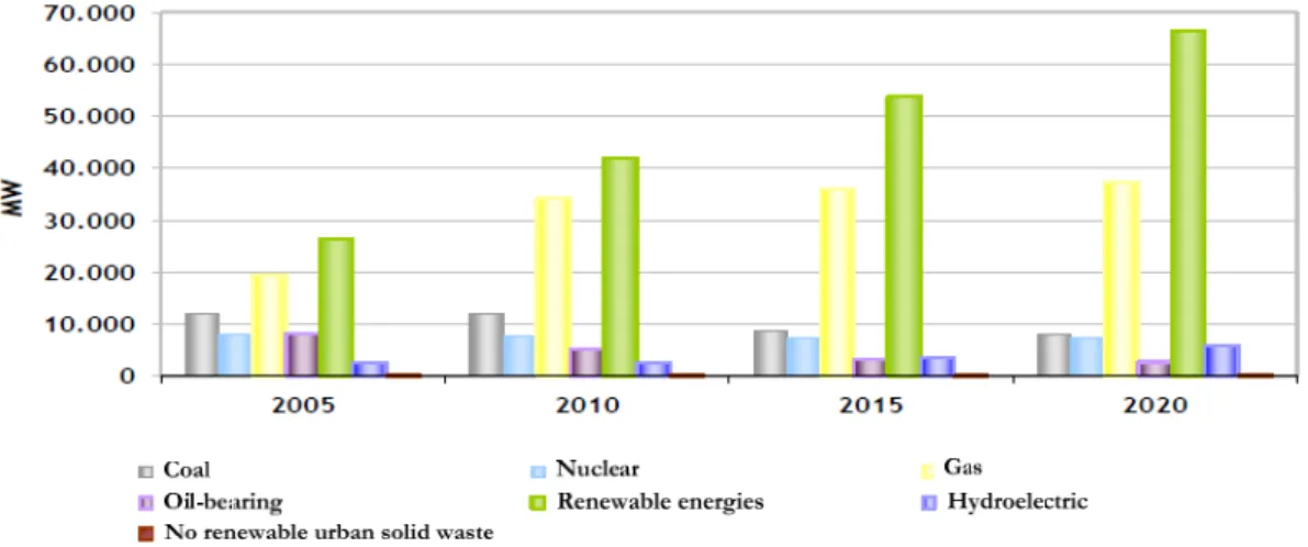
(21) Control Contributions to the Universal Operation of Wind Turbines. Chapter 1. Introduction 1.1. Framework. The world economical progress and the energy market are two concepts intimately linked. The worldwide economy is mainly running on fossil fuels. In such conditions, the European Union (EU) analyzes its critical energy dependence in its green and white papers [Whi, 1997] [Gre, 2006]. More than half (54.1 %) of the EU-27’s gross inland energy consumption in 2010 came from imported sources [Estat, 2009], which supposes a 35% increment in the last three decades. If the forecasts are correct, the imported resources will raise up to 66 % before 2020. The tendency of world oil prices and the oligopolistic nature of the market evidence an unsustainable situation for the EU. This very bleak picture of the future is even worse if environmental issues are considered. Energy related emissions account for almost 80% of the EU’s total greenhouse gas (GHG) emissions. The agreement undersigned in the Kyoto protocol [Kyo, 1998] established a set of minimal objectives for reducing CO2 emissions and reduce the global energy consumption. Europe’s Kyoto commitment for 2020 consists in a 20 % reduction of GHG emissions. 1.1.1. Renewable energy. During the past decade, the EU has emerged as the world’s leading region in developing and implementing renewable energy technologies. About one third of the estimated global investment of 150 billion USD in energy efficiency and renewable energy was in the EU in 2007. As a consequence, the European Environment Agency (EEA) have recently determined that emissions from the EU-27’s have fallen 18 % since the 1990 baseline year, including 2.5. Mario Rizo Morente 1.
(22) Chapter 1: Introduction.. percent in 2011 when compared to 2010 [Eea, 2012]. However, big efforts are still required in order not to fail in its energy ambitions. The Commission proposes a new energy strategy towards 2020 [Ene, 2012]. • A 20% enhancement of the energy efficiency. • A 20% of renewable energies contribution in the primary energy generation. • A 20% reduction of the GHG emissions. This strategy should help to create market conditions which stimulate higher energy savings and more low carbon investments, to exploit a wide range of centralized and distributed renewable energy. Within the Spanish national framework, the renewable energy generation has been grown more than 500 % in the last decade. In 2011, it covered almost a third (32.4%) of the total electric demand. The wind power generation supposed the 16 % of the total electric demand, experiencing an expansion of 500 % of the installed power in the last decade. In 2010, the electric generation of renewable energies has avoided the import of oil barrels with a total cost of the 0.22% of the gross domestic product (GDP). As a consequence, in the last five years, the CO2 emissions related to electric generation was reduced a 42%. The Spanish energy policies closely follow the European guidelines. The national strategies are collected in [Per, 2011] for the period 2011-2020. The global objective is mainly focused on covering a 20.8% of the primary energy generation with the participation of renewable energies, in contrast with the current 11.3%. It will suppose a 38.1% of the total electric demand and a saving cost of € 1.700 M of fossil fuel imports per year.. Fig. 1.1: Evolution of the installed electric capacity in Spain. Source: MITyC/ IDEA.. 2. Mario Rizo Morente.
(23) Control Contributions to the Universal Operation of Wind Turbines. 1.1.2. Distributed power generation. The great part of the structure of the current electric system is based on the centralized paradigm. The electricity generation points are highly concentrated and integrated far from the consumption points. The centralized scheme was the result of: 1) economies of scale where the marginal cost of electricity production was reduced with higher ratings of steam turbines, 2) innovation in electricity transmission reducing the losses 3) environmental constraints such as the distance between generation units and the cities, among others. However, the centralized philosophy has become antiquated and currently presents clear disadvantages: 1) the distances covered by the transmission and distribution networks still lead to remarkable transport and transformation losses, 2) the continuously increasing electricity demand makes necessary a notorious investment on the transmission and distribution networks in the following twenty years, 3) in the 1960s the marginal cost started to increase with the sizing of centralized sourced, 4) the rural electrification supposes connecting remote areas with small consumptions, quite inefficient from the economical point of view, etc. Although the distributed generation (DG) has historically been used to complement centralized generation, the causes of the recent explosion resides on the liberalization of the electricity markets and the concerns over the GHG emissions [Iea, 2002]. The voltage source converter (VSC) has become the most widespread interface unit within the electric DG. Within the DG, the microgrids play an important role in the enhancement of the power system reliability. The term microgrid accepts many definitions. In [Lasseter, 2002], it is defined as “a cluster of loads and microsources operating as a single controllable system that provides both power and heat to its local area”. A more modern and accurate definition is given in [Kroposki, et al., 2008]: “systems that have at least one distributed energy resource and associated loads and can form intentional islands in the electrical distribution systems with a variety of benefits including improved reliability”. As indicated in Fig. 1.2, a classic microgrid mainly consists of DG units, loads, distributed storage (DS) systems and switches. The control of the microgrid is a centralized architecture with communication links. It usually operates grid-tied until a fault occurs. In that instant, the low voltage ride-through (LVRT) requirements should be initially fulfilled and after that, the switch is opened and the microgrid becomes an island. The principal function of the DS system is to regulate/absorb the power mismatch between the generation and the consumption during the island operation. However, this feature is limited to the storage capacity and incrementing it is not always physically feasible or economically assumable. Due to the constraints that it supposes, the total aggregated power of a microgrid hardly ever exceeds 100 kW. A global problem like the high penetration of DG is analyzed from a local point of view by means of the microgrid concept in [Piagi, et al., 2006].. Mario Rizo Morente 3.
(24) Chapter 1: Introduction.. Fig. 1.2: Microgrids and components. Source: [Kroposki, 2008].. 1.1.3. Power quality. Power quality, “voltage quality”, “current quality” and “service quality”, among others, are usually referred as the measure, analysis and improvement of the bus voltage to maintain a sinusoidal waveforms at rated magnitude and frequency [Fuchs, et al., 2008]. In general, the power quality phenomena: leads to the tripping of equipment and the interruption of production operation, endangers power system operation, inserts additional losses, etc. Electronic equipment and companies have become much more sensitive to voltage disturbances in the recent decades. The electric supply is more and more considered as a basic resource and an interruption can suppose a sensitive loss in the companies’ profits. Besides, the tripping of the electronic equipment has been considered by the electric companies as one of the principal causes of poor power quality. On the other hand, the high increment of power electronics in consumer equipment and renewable energies has raised the harmonic content in the bus. There are several criterions for classifying the power quality phenomena. The standard [IEEE-1159, 2009] uses the magnitude and duration of the phenomena while [Bollen, 2002] distinguishes between voltage and current variations and events. Interruptions, dips and swells are categorized as power quality events: • An interruption occurs when the bus voltage is reduced below the 10%. Grid faults that trigger protections, broken conductors and operation interventions are the main causes of interruptions. It can be further categorized as function of the duration or what is equivalent, regarding the way of restoring it (automatic switching, manual switching or repair/replacement of the faulted component). According to [IEEE-1159, 2009]: a momentary interruption lasts between 0.5 cycles and 3 s, the duration of a temporary interruption is from 3s up to 1 min and a long-duration or sustained interruption lasts more than 1 min.. 4. Mario Rizo Morente.
(25) Control Contributions to the Universal Operation of Wind Turbines. • A dip or sag supposes a reduction of the rms voltage from 90% up to 10%. Voltage dips are usually caused by the energization of heavy loads, the starting of large induction motors, line-to-ground faults and the load transferring form one power source to another. Long-duration dips are usually referred as undervoltage. • A swell is defined as the increment of the voltage magnitude between 1.1 and 1.8 p.u. Long-duration swells are usually referred overvoltage. Voltage unbalances and waveform distortion are included within the steady-state phenomena: • The voltage unbalance is produced when the magnitudes of the three-phase voltages are not identical or the phase differences between them are different from 120 degrees. The voltage unbalance can be assessed by means of the computation of the zero and negative sequence components. • The waveform distortion is referred as the deviation from a sinusoidal wave. Harmonic distortion is the most representative phenomena. It is based on the voltage and current contamination with frequency components that are integer multiples of the fundamental frequency. Industrial nonlinear loads and residential loads based on power electronic devices are frequent harmonic sources. Many detrimental effects are related with the presence of harmonics component in the utility. The standardization and utility efforts have resulted in a good power supply in most developed countries. The consumer’s perception is that the electric resource is always available and their position becomes more and more demanding. However, the continuously growth of the energy consumption is taking the current electric system to the limit [Iea, 2011]. In fact, according to [Iea, 2005], the most recently cases of blackouts are related with the power system design weaknesses, overexploitation and lack of redundancy. Besides, some factors like the downturn in the economy and the drive of developing countries (i.e. China and India) have forced the companies to extend their products to weaker power systems, where the power quality has not been addressed with a strong regulation yet. All these facts make clear the following two statements: • The continuous power supply avoiding any kind of interruption or dip is still a trendy power quality issue. • There is still a wide range of improvement regarding the power supply reliability. The use of series and shunt VSC for improving the power quality issues is quite widespread. The power supply reliability can be increased with Voltage Controlled Voltage Source Converters (VCVSCs), like Dynamic voltage restorer (DVR) [Wessels, et al., 2011], Uninterruptible Power Supply (UPS) systems [Guerrero, et al., 2005] or grid-connected converters working in stand-alone mode [Balaguer, et al., 2011]. The voltage stability and. Mario Rizo Morente 5.
(26) Chapter 1: Introduction.. harmonic distortion are also a matter of Current Controlled Voltage Source Converters (CCVSCs), such as Static Synchronous Compensators (STATCOMs) [Ortiz, et al., 2008], active filters [Yuan, et al., 2002] and any DG system connected to the main grid. 1.1.4. Ancillary services: voltage and frequency regulation. In electric grid systems with a high penetration of DG units or with a certain degree of weakness, the demand of ancillary services becomes quite interesting. The grid codes require the grid-connected DG units to modify the active and reactive power injections with the purpose of increasing the regulation capacity of the system frequency and voltage. Fig. 1.3 shows the frequency regulation demanded to WTs connected to the Distribution Network in Demark. Generally, the WT can inject the maximum available power in the frequency range indicated by the dead-band. If the frequency rises, as a consequence for example of high load shedding, the WT is forced to reduce the injected power. The power mismatch between available wind power and injected electric power can be initially solved with the kinetic storage and after with the pitch control. With the 50 % down-regulation, the WTs are also dotted with regulation capacity over lower frequencies. Fig. 1.4 depicts the voltage regulation curve demanded in the South African grid code by means of the injection of reactive power. These ancillary services where the active and reactive powers are modified in function of the frequency and voltage are intimately linked with the inverse droop. It is important to distinguish it with the direct droop employed as a power controller in gridconnected where the phase and magnitude of the voltage injected by the DG unit are configured with the aim of tracking the active and reactive power references (see subsection 2.1.2).. Fig. 1.3: Frequency regulation curve in Danish grid code [UNIFLEX-PM, 2006].. 6. Mario Rizo Morente.
(27) Control Contributions to the Universal Operation of Wind Turbines. Fig. 1.4: Voltage regulation curve in South African grid code [GCSA, 2012]. 1.2. Thesis development context. In a general framework, this Thesis introduces the concept of Universal Operation. This term just proposes a revision of the microgrid philosophy. Given the necessity of further improving the power supply reliability, the Universal Operation’s goal is providing a flexible and economically feasible adaptation of the existing low and medium power (up to 100kW) DG units working as grid-connected sources into potentially island-forming units. Once fault is cleared, the parallel sources are again connected to the grid. This procedure is already covered by the grid-interconnection standards [IEEE-1547.4, 2011]. The microgrid philosophy makes use of a complex and extensive system structure (diesel generators, storage systems and high combination of different DG units) to indefinitely extend the autonomous operation. In contrast, the target of the Universal Operation philosophy is keeping the power supply under interruptions in the range of minutes as an ancillary service to the local loads. Longer interruptions are less likely to occur. To that concern, the Universal Operation philosophy implements a distributed control architecture following the minimization of communication links and enhancing the flexibility and scalability. In this Thesis, the Universal Operation is particularly applied to on-shore low and medium power WTs. The proposed concept perfectly matches with wind power due to the current high penetration. Besides, the inherent storage capacities of this technology offer the possibility of removing any expensive external storage system to balance the power consumption and generation, given the mentioned duration of the interruptions to be covered. The external storage doubtlessly increases the regulation of the power mismatch and the redundancy and thus, the continuous supply. However, the objective is to provide a direct and economical solution restricting the modification of the existing plants. Therefore, the Universal Operation of WTs a priori represents several challenges. As global requisites, during the island operation, each isolated source should participate in the regulation. Mario Rizo Morente 7.
(28) Chapter 1: Introduction.. of the local voltage and the load should be efficiently shared between them. As particular requirement, in order to extend the island operation, each WT should delay the shut down condition by means of an optimum management of the balance between injected and generated powers. In the grid-connected mode, the requisites are well-known: a power control with good robust stability and efficient response to grid disturbances. Although the power supply reliability is the main power quality factor this work is focused on, it does not lose the insight of other issues like the harmonic distortion and unbalanced conditions. On the other hand, the control strategy of the isolated network should assure smooth transitions between island and grid-connected modes, avoiding any harmful situation that would lead to the activation of the protections. To cover all these requirements, this Thesis proposes a list of hardware and control modifications applied to common WTs. A two level full-power converter WT with a permanent magnet synchronous generator (PMSG) is taken as the base model to set out the proposed modifications. The full-power converter is composed by an inverter or grid-side (GS) converter and a rectifier or machine-side (MS) converter. With the adequate regulation strategy, this hardware configuration offers a good response under voltage dips and other types of faults. In contrast with induction generators (IG), the PMSG provides a high power density and a reduced power factor. A common WT with the proposed hardware and control modifications results in the renamed universal wind turbine (UWT). Fig. 1.5 presents a first schematic overview of a potential island section composed by several UWTs connected in parallel with local loads and with the main grid through a local circuit breaker. Additional DG units with sources of other nature might be considered. Nevertheless, the aggregated power is limited by the overall ratio storage capacity – rated power. This ratio takes into account all the storages capacities (at least the kinetic storage of the UWTs) and the overall power rating. As long as additional DG units without inherent storage resources are added, the ratio is reduced and so does the capacity for dealing with instantaneous power mismatches. A lower threshold of this ratio establishes the limit where the Universal Operation is feasible. The hardware modifications are mainly focused on making feasible the island operation. They consist on a circuit breaker that isolates the complete system after the LVRT operation and a capacitor added to the L-filter to improve the voltage regulation of the island (if not present). The circuit breaker is autonomously regulated. Its management system monitors the PCC voltage, detects any islanding and fault condition and sends the PCC voltage and information about the state of operation (grid-connected, island o synchronizing) to the UWTs through a communication link. This is the only communication link considered in this work. The maximum latency of the communication should assure the right performance of the UWTs. In case the system is composed by just one UWT or in low power urban applications, where distances are quite reduced, the communication link is removed and the circuit breaker regulation is just implemented in the UWT.. 8. Mario Rizo Morente.
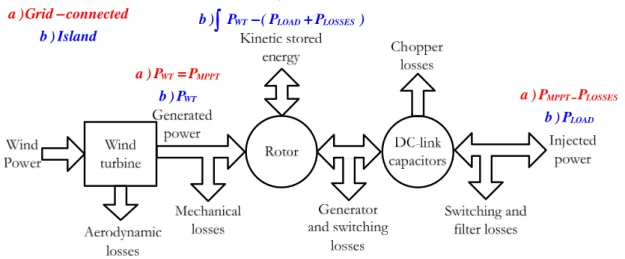
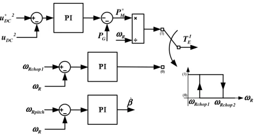
(29) Control Contributions to the Universal Operation of Wind Turbines. The greatest part of the efforts made in this work is driven to the control area of the UWT. As shown in Fig. 1.5, the control is divided into the MS controller and the GS controller. The key point of the proposed control modification resides in a high versatility with a common structure to deal with all the requirements of each mode. The proposed strategy is briefly summarized in the following lines. The control is divided into stages from outer to inner controllers. The top level is on charge of the power balance. Fig. 1.6 presents a drawing with the power flow and the more representative elements that take part on it. In grid-connected, the UWT behaves as a grid-feeding system where the injected power is fixed by the maximum power point tracking (MPPT) algorithm of the MS controller. Then, the GS controller just injects the same amount of power (minus power losses) to get an energy balance. On contrary, the island operation is more challenging. The UWT should now behave as a grid-forming system, controlling the local voltage and frequency. However, in order to optimize the iteration with other parallel sources and avoid circulating currents, the voltage and frequency regulation is smoothened with some droop constants. The power transfer is fixed in the GS controller by the local loads. The MS controller should them readapt the power it injects into the DC-link to get the desired energy balance. However, it is difficult to have a perfect match between current generation and consumption. For that purpose, the control strategy takes advance of the kinetic storage of the rotor, the braking chopper and the pitch angle to deal with power mismatches. In case of more consumption than generation, this negative power mismatch is resolved with kinetic energy, decelerating the rotor. The rotor speeds up in the opposite case. The breaker chopper is also employed for dealing with positive power mismatch. The system can additionally make use of the pitch control to carry out a further regulation of the generated power, provided that the dynamics of its actuation does not allow acting over transients. It is then employed to enhance the steady-state response. If the kinetic storage upper or lower limits are reached, the system should trip out and the power supply disappears. In order to minimize the probability of this to happen, the power sharing strategy establishes that systems with more energies reserves should participate with more power. This logically adds an extra degree of regulation of the storage reserves without any direct communication between the involved parts. This Thesis is mainly enclosed in the Italian public project entitled “Universal small windturbines (grid-connected, stand-alone, micro-grid)”. This Thesis contributes in two of the seven key issues of the project: • Development and implementation of the most proper control techniques to control the active and reactive power flow between MS and GS systems and to operate with different grid connection conditions and wind conditions; a power sharing algorithm will be included in the control system to manage the power exchange also in case on microgrid mode. • Implementation of the algorithms on digital board based on embedded-on-chip systems.. Mario Rizo Morente 9.
(30) Chapter 1: Introduction.. r iS. r i2. r i1. Rchop. C DC uDC r e PCC. State. State. Zl 1. Z lN. Z li. r e ISL. r e PCC. r e PCC State. Fig. 1.5: Aggregation of several UWTs and the local circuit breaker with their respective schemes of control. a )0. a )Grid − connected b ) Island. b )∫ PWT − ( PLOAD + PLOSSES ). a ) PWT = PMPPT b ) PWT. a ) PMPPT − PLOSSES b ) PLOAD. Fig. 1.6: Flowchart of the power transfer through the elements of a WT.. 1.3. Related publications. As a result of the work developed in this Thesis, several conference and journal publications have been carried out. They are collected in function of the topic they contribute as follows: Universal operation philosophy (1, 2 and 3), voltage and current control (4 and 5), synchronization (6, 7 and 8) and sensorless control of machine side converter under disturbances (9 and 10). 1. M. Rizo, M. Liserre, E. Bueno, F.J. Rodríguez and F. Huerta, “Universal wind turbine working in grid-connected and island operating modes”, Math.Comput.Simul., no. 0, 2012. 2. M. Rizo, E. Bueno, A. Dell’Aquila, M. Liserre and R.A. Mastromauro, “Generalized controller for small wind turbines working grid-connected and stand-alone”, 2011 International Conference on Clean Electrical Power (ICCEP), 2011.. 10. Mario Rizo Morente.
(31) Control Contributions to the Universal Operation of Wind Turbines. 3. M. Rizo, M. Liserre, E. Bueno, F.J. Rodríguez and C. Giron, “Universal Operation of Wind Turbine Systems without Storage”, Submitted to IEEE Transactions on Sustainable Energy 4. M. Rizo, M. Liserre, E. Bueno, F.J. Rodríguez and C. Giron, “Voltage Control Architectures for the Universal Operation of DPGS”, Submitted to IEEE Transactions on Power Electronics. 5. M.Rizo, M. Liserre, E. Bueno, A. Rodríguez and F.J. Rodríguez,“Different Approaches of Distortion-Free Stationary Reference Frames Saturators” To be submitted. 6. F.A.S. Neves, M.C. Cavalcanti, H.E.P. de Souza, F. Bradaschia, E.J. Bueno and M. Rizo, “A generalized delayed signal cancellation method for detecting fundamental-frequency positive-sequence three-phase signals”, IEEE Transactions on Power Delivery, vol. 25, no. 3, 2010. 7. F.A.S. Neves, H.E.P. de Souza, F. Bradaschia, M.C. Cavalcanti, M. Rizo and F.J. Rodriguez, “A space-vector discrete fourier transform for unbalanced and distorted three-phase signals”, IEEE Transactions on Industrial Electronics, vol. 57, no. 8, 2010. 8. M. Rizo, F. Huerta, E. Bueno and M. Liserre, “A synchronization technique for microgrid reclosing after islanding operation”, IECON 2012 - 38th Annual Conference on IEEE Industrial Electronics Society, 2012. 9. M. Rizo, A. Rodriguez, E. Bueno and F.J. Rodriguez, “Robustness analysis of wind turbines based on PMSG with sensorless vector control”, IECON 2010 - 36th Annual Conference on IEEE Industrial Electronics Society, 2010. 10. M. Rizo, A. Rodriguez, E. Bueno, F.J. Rodriguez and C. Giron, “Low voltage ride-through of wind turbine based on interior permanent magnet synchronous generators sensorless vector controlled”, 2010 IEEE Energy Conversion Congress and Exposition (ECCE), 2010.. 1.4. Document structure. The document of this Thesis is organized in five Chapters and the Appendix. Chapter 2 contains the knowledge review of the power controller for grid-connected and island operations, the voltage controller of LCL and LC filters, the power sharing strategies and the regulation of unbalanced conditions. The last section of this chapter presents the objectives of the Thesis. Chapter 3 introduces the proposed general control structure for both GS and MS converters and establishes the bandwidth of each loop. Besides, it covers the description of the power filter setup, the DC-link voltage controllers and the GS voltage control for the Universal Operation. Regarding the latter, an extensive comparison of several voltage control architectures attending the Universal Operation issues is carried out.. Mario Rizo Morente 11.
(32) Chapter 1: Introduction.. Chapter 4 presents the GS power controller. The GS power control is analyzed from the point of view of the control philosophy: current and voltage controlled. Accurate models are provided for tuning the regulator to meet the imposed requirements. Furthermore, a power sharing strategy is proposed with the aim of efficiently managing the total kinetic energy and extending the island operation until the recovery of the grid. Finally, a statistical study, which supplies accurate data regarding the real improvement over power supply reliability ratios when using the Universal Operation of WTs, is developed. It analyzes the probability of cover an interruption as function of the wind profile and load consumption and the reduction of the power supply interruption. The contents of Chapter 5 are related to the treatment of unbalanced conditions. First of all, the relation between unbalanced and distorted control references is analyzed. Based on that study, the power control has dotted of a dual phase structure and an interesting novel saturator philosophy is proposed for avoiding the distortion of voltage and current references under unbalanced conditions. Besides, a power control block is implemented for controlling the oscillating power during unbalanced conditions by means of the injection of negative sequence voltage. Chapter 6 collects the synchronization technique proposed for the Universal Operation. The key point of this strategy resides on the implementation of a virtual impedance in each unit that provides two beneficial features: it counteracts the voltage drop across the filter output impedance and it can be configured to again share the power as function of the kinetic storage. Chapter 7 contains the experimental and simulation results that validate the theoretical approaches. Finally, Chapter 8 summarizes the conclusions obtained from the development of the Thesis and presents the future works. The Appendix introduces the inner control of the MS: a sensorless vector control of the PMSG.. 12. Mario Rizo Morente.
(33) Control Contributions to the Universal Operation of Wind Turbines. Chapter 2. Knowledge Review and Thesis Objectives The work of this Thesis is mainly oriented to the research of control algorithms to make feasible the Universal Operation of WTs without extra storage systems. This chapter makes an extensive review of the most relevant previous works regarding the power control and power sharing of isolated and grid-connected systems, voltage control of LC and LCL filters and control performance under unbalanced conditions, etc. Then, the Thesis objectives are settled down following those research paths that still contains weak points not only for the Universal Operation but also for other issues in common with grid-connected DG systems.. 2.1. Knowledge review. 2.1.1. Inner controllers: current and voltage controls. Before getting deeper, it is important to first review the existing types of VSC control philosophies. The control philosophy of a converter is mainly given by the ac variable under control in the loop: current or voltage. In those cases where both voltage and current are regulated, the variable that defines the philosophy of control is the outer one. Attending to the above mentioned, it can be distinguished between VCVSCs and CCVSCs. The power supply reliability can be increased with VCVSCs, like DVR, UPS or grid-connected converters working in stand-alone mode within a microgrid, as UWTs. The voltage stability and harmonic distortion are a matter of CCVSCs, such as STATCOMs, active filters and any DG source connected to the main grid. Fig. 2.1 contains the CCVSC and VCVSC topologies along with their respective general controllers.. Mario Rizo Morente 13.
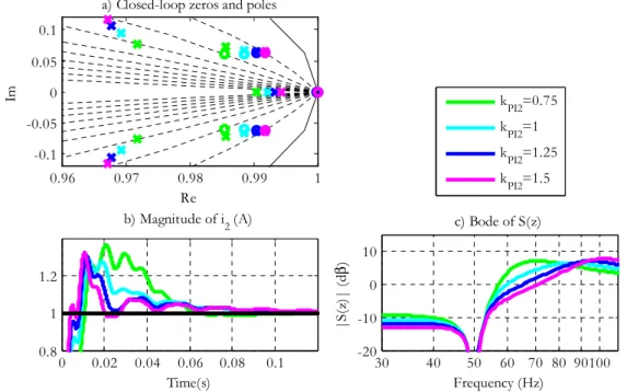
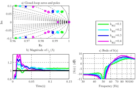
(34) Chapter 2: Knowledge Review and Thesis Objectives. Pi. Po. R f Lf. Rg Lg. PCC. r eG. uDC. r ig r ig. r∗ ulim uDC. Pi. r u∗. Po. r i g∗lim. R1 L1. r i g∗max. r i g∗. r i1. uDC. r∗ ulim. uDC. r u∗. r i1 r i1∗max. Cf. r vC∗. imax. r vC∗. Fig. 2.1: a) Scheme of a general CCVSC with its respective inner control loop and b) VCVSC topology and general block diagram of capacitor voltage control.. In this subsection, previous works focused on the control of the voltage across the filter capacitor are reviewed. The voltage controller plays a great role in the universal controller. No matter the operation mode (grid-connected, island or synchronization) or the selected power control architecture, it is always the inner block and the basis for performing a good regulation. Several works have been published regarding the voltage control of LC and LCL filters. In the great majority of works, the employ of the LC filter is preferred due to its better voltage regulation and power factor. On the other hand, the LCL-filter supposes a good tradeoff between the island and grid-connected operations. Actually, any LC can be viewed as a LCL if the feeder or the transformer impedances are taken into account. Fig. 2.2 depicts a diagram block of the control plant constituted by the LCL filter. As shown, in this case, the PCC voltage is considered as the disturbance of the control loop. The currents and the capacitor are sampled. There are several ways to implement the voltage control. The most classic one consists on implementing it in the synchronous reference frames or dq-axis. By applying the 14. Mario Rizo Morente.
(35) Control Contributions to the Universal Operation of Wind Turbines. r e. r i2. PLANT. Controller. r i1. ZOH. r uG. r vC. 1 Rf + sLf. r i1. r i2. 1 R2 + sL2. r iC. 1 + RD sC f. r vC. r iC. r vC Fig. 2.2: Block diagram of the plant for the voltage control in the continuous-time domain.. transformation into this rotating axis, the ac variables become dc quantities. Then, they can be easily regulated through PI controllers. It is quite weird to use single-loop architectures in dqaxis under the inability of this option to cancel the cross-coupling terms. Therefore, the voltage control is additionally complemented with an inner current control of the converter current or the capacitor current as in [Balaguer, et al., 2011], [Mehrizi-Sani, et al., 2010] and [Kim, et al., 2011]. One of the main advantages of the control in the dq-frames is the direct coupling with the active and reactive powers. Nevertheless, there are still many drawbacks associated to the control in dq-axis. • The cross-coupling cancellation terms does not ideally decouple the dynamics between the d and q axis. • The efficiency of the control is quite sensitive to the performance of the PhaseLocked Loop (PLL) of the synchronization system. Besides, the additional transformation into the dq-axis slightly increases the computational weight of the controller. • The most crucial aspect resides in the simultaneous control of positive and negative sequences. The control of UWTs should provide optimum performance under unbalanced loads in island operation and unbalanced faults during grid-connected operation. The control of the negative sequences demands the definition of an additional dq-axis rotating in clockwise and the insertion of an additional PI controller working in that negative sequence frames. Besides, the synchronization system has to be equipped with a sequence detector and it not always provides a good decoupling between sequences and axis. Moreover, these sequence detectors are based on the generation of quadrature signals. Then, the settling time is limited by the time required in the sequence detection, close to a quarter of the fundamental period of the grid. The previous statements make clear that the implementation of the voltage control over the dq-frames is very poor. The regulation of ac signals in the stationary reference frames or αβ-axis seems to solve the drawbacks described above. There are no cross-coupling terms, high dependence on PLL and the control of positive and negative sequences is done with just Mario Rizo Morente 15.
(36) Chapter 2: Knowledge Review and Thesis Objectives. one Proportional + Resonant (PR) controller without the need of defining extra virtual axis and using sequence detectors. PR controllers offer an infinite gain at the control frequency and provide zero error in steady-state. There are lots of possible configurations the voltage controller can attend to. They can be simply classified as: single-loop and double-loop. Fig. 2.3 contains both control architectures. The single-loop strategies contain just one feedback, the capacitor voltage. Double-loop control architectures additionally contain an internal feedback of the converter current or the capacitor current. In case of double-loop architectures, it has to be distinguished between inner and outer controllers. The outer controller, which regulates the capacitor voltage, consists on a PR controller while the inner controller can be implemented with a P or a PR. In [Loh, et al., 2003], a voltage control based on a double-loop is analyzed from the point of view of the variable under control in the inner loop focused on UPS applications. The derivative behavior of the capacitor current can increase the bandwidth in contrast with the integral behavior of the converter current. A similar study is carried out in [Li, et al., 2007] and [Li, 2009] for DVR applications. Besides, the single-loop architecture is also studied with the possibility of adding a feedforward of the voltage reference. Although the feedforward improves the settling time, the resonance damping of the filter becomes poorer. In fact, the addition of the inner current loop can further damp the filter resonance. The general closed-loop scheme proposed in [He, et al., 2012] shows that a double-loop scheme is equivalent to a single-loop architecture with two virtual impedance terms in parallel. These terms are linked with the internal and external impedances. The former is configured attending to damping purposes while the latter can be employed for harmonic cancellation. r e PCC Voltage Controller. r vC*. PR. z. -1. r uG∗. PLANT. r vC. r vC a) Voltage Controller. r vC*. PR. r vC. * C. r e PCC. Current Controller * 1. i or i. P or PR. z -1. r uG∗. r vC PLANT. r r iC or i1. b) Fig. 2.3: Voltage control in the stationary reference frames: a) Single-loop architecture and b) double-loop architecture.. 16. Mario Rizo Morente.
(37) Control Contributions to the Universal Operation of Wind Turbines. 2.1.2. Power Control in grid-connected mode. As illustrated in the previous subsection, it is clear that the system must adopt the control philosophy of VCVSCs during the island operation. However, the Universal Operation also contemplates the grid-connected operation after the resynchronization process when the grid fault is cleared. In the case of the grid-connected operation, the tendency is usually to follow a control in current source [Kazmierkowski, et al., 1998]. An example where the control scheme leaves the VCVSC philosophy in island mode to adopt a CCVSC can be found in [Balaguer, et al., 2011]. In [Yao, et al., 2010], the voltage controller is kept and its reference is supplied by an outer current controller (which gives the current source identity) regulating the output current of an LC filter. However, since the development of the droop control and the standardization of the reconnection of isolated DG areas [IEEE-1547.4, 2011], the VCVSC is also gaining importance in grid-connected applications [Katiraei, et al., 2006], [Lasseter, 2002], [Li, et al., 2004], [Li, et al., 2009], [Hasanzadeh, et al., 2010], [Mohamed, et al., 2008], [Mastromauro, et al., 2009] and [Vasquez, et al., 2009a] under the premise of smooth operation mode transitions. For that purpose, the droop control is readapted by adding an integrator in the voltage magnitude-reactive droop in [Brabandere, 2006] and [Guerrero, et al., 2009]. Works like [Guerrero, et al., 2011] and [Vasquez, et al., 2009b] are examples where the VCVSC regulation philosophy is used in both island and grid-connected mode. Further discussion about the power controller focused on the management of unbalanced conditions is given in subsection 2.1.3. 2.1.3. Power Control in island mode. Regarding the island operation, each DG unit should actively participate in the regulation of the local voltage and share the load power demands with the rest of parallel sources. If every parallel source adopts a grid-forming strategy (with fixed voltage magnitude and frequency references), the non ideal measurement of voltage and frequency leads to a control struggle between them. The use of frequency and voltage droops in the power control, as in the primary frequency control of synchronous generators, smoothes the connection and interaction of parallel sources. The concept of “plug & play” is satisfied with this control strategy improving the autonomy of each parallel source and the versatility of the isolated system. The traditional frequency and voltage droops are expressed by (2.1) and shown in Fig. 2.4. The droop curve is characterized by the droop constants, kPf and k QV , and the base points, ( PG∗ , ω ∗ ) and ( QG∗ ,VC∗ ). These points belong to the droop curve independently the value of the slope.. Mario Rizo Morente 17.
(38) Chapter 2: Knowledge Review and Thesis Objectives. ω − ω ∗ = k Pf ( PG∗ − PG ). (2.1).. VC −VC ∗ = k QV ( QG∗ − QG ) ω. VC. ω∗ ω1. VC∗ VC 1. k Pf. PG∗ a). PG 1. PG. k PV. QG∗. QG 1 QG b). Fig. 2.4: a) Traditional active power-frequency droop and b) reactive power-voltage magnitude droop.. As shown in Fig. 2.4, the droop regulation is situated between a grid-feeding (no voltage regulation capacity) strategy and a grid-forming (no power coordination capacity between parallel sources) strategy. Actually, the requisite of regulating the local voltage during the island operation lies on the voltage controller, while the droop control is used to coordinate the different parallel sources within a higher regulation level. As a consequence of the power sharing, the regulation based on droop introduces steady-state voltage magnitude and frequency drifts, which logically affects the power quality Two main options are reported in the bibliography for implementing the droop control. The conventional or direct droop is the most common alternative adopted by the majority of the works. It applies a voltage magnitude and frequency droops in function of the injected active and reactive power as shown in Fig. 2.4. On contrary, the second option, denominated inverse droop, fixes the active and reactive power references in function of the local voltage magnitude and frequency [Wijnbergen, et al., 2005]. The inverse droop is generally used in CCVSC to add some grid-supporting capacity. With this topology and during the island operation, there is not capacity for regulating the voltage and frequency if the unit is the sole source or its rating power is high in contrast with the overall power of the parallel sources. In [Hauck, et al., 2002], the inverse droop is also applied to VCVSC resulting in a more complex system. The conventional droop control perfectly fits in the VSVSC control structure, where the voltage reference is calculated in function of the active and reactive powers. In [Brabandere, 2006] and [Zhang, et al., 2010], a Dynamic Phasor Model is obtained for describing the dynamics of the non-linear plant. In [Guerrero, et al., 2004], a small-signal analysis model is constructed around a bias-point. Both procedures are equivalent. Based on the model, [Guerrero, et al., 2004] proposes the addition of derivative terms for improving the transient response of the droop control while the steady-state response is not affected. However, there are other handicaps associated to the droop control. In large power systems, the transmission line is usually characterized as highly inductive. However, this fact cannot be affirmed in low-voltage application, leading to a coupling between the active and. 18. Mario Rizo Morente.
(39) Control Contributions to the Universal Operation of Wind Turbines. reactive power. A quite complex solution was proposed by [Dai, et al., 2008] based on a Newton-Raphson parameter estimation and feedforward control. In [Li, et al., 2009], a virtual impedance term is implemented to modify the total output impedance and remove the coupling. In [Brabandere, et al., 2007], a matrix that creates virtual decoupled versions of the active and reactive power is employed. The selection of the droop slopes is not only related to stability issues but should also take into account the trade-off between power quality and power sharing [Guerrero, et al., 2004] [Guerrero, et al., 2005] [Guerrero, et al., 2009]. As long as the droop slopes are getting higher, the sensitivity for detecting voltage and frequency deviations is increasing, which improves the efficiently when sharing the local load between the parallel sources. However, the high voltage and frequency deviations logically affect the power quality supplied to the loads. Then, the droop coefficients should be configured in order to respect the maximum voltage magnitude and frequency drifts (5% and 2%, respectively). Finally, the last drawback of the conventional droop control is associated to the presence of nonlinear loads. The conventional droop is suitable for balancing the active and reactive power but not for sharing harmonic currents. The island operation provides an extra way of improving the power supply ratios (reducing the number of interruptions and decreasing the average duration of them). The success highly depends on the ability of dealing with power mismatch between generation and consumption of each UWT. A bad regulation of the power mismatch can bring the shutting down condition very fast. On contrary, a good strategy delays the shutting down condition or even avoids it improving the power supply reliability. It is a challenging task and not always possible to be achieved under high mismatches between load consumption and available generation. The DC-link voltage and the rotor speed are the main internal factors the island regulation should be focused on. In [Haque, et al., 2010] and [Bhende, et al., 2011], the increment of the regulation capacity over the power mismatch given by storage devices is emphasized. However, the possibility of equipping each existing WT with energy storage is not feasible due to the high investment it supposes [Chen, et al., 2009]. As described in Chapter 1, the power that crosses the full power converter in the island mode should be adapted in accordance with the load consumption. In [Mlodzikowski, et al., 2011], the GS converter regulates the DC-link voltage through the voltage it injects to the loads so that the load consumption is wrongly modified. This modus operandi where the load voltage and power are modified as function of the DC-link voltage can cause serious damages to the loads. A correct procedure should just inject the power demanded by the loads. This is achieved by keeping the island voltage at its rated value, which permanently assures the supply of the demanded power. The island voltage regulation is then carried out by the GS converter. The MS converter controls the DC-link voltage and hence, balances the power flow. Any power mismatch between generation and consumption is counteracted by the kinetic energy stored on the rotor. Positive mismatches speed the rotor up while negative ones reduce the speed. This operating principle is applied to just one WT Mario Rizo Morente 19.
(40) Chapter 2: Knowledge Review and Thesis Objectives. within an island in [Kanellos, et al., 2008]. This WT performs the regulation of the island voltage while the rest acts like current sources. The aggregation of additional sources can complicate the voltage regulation. The master WT experiences a particular high negative power mismatch, as the total power is not uniformly shared, so it can run out of energy reserves and be tripped off. Then, as none of the remaining WTs participate in voltage regulation, the complete system is shut down even though the remaining WTs still contain kinetic reserves. The versatility, integrity and scalability are remarkably improved when all the parallel sources participate in the voltage regulation by using the droop control as a smooth interconnection technique. However, the island performance is very sensitive to the tripping of one source due to the lack of kinetic storage. It is important to perform a management of the energy reserves. In [Kanellos, et al., 2008], the torque reference that controls the DC-link voltage is slightly modified in function of the rotor speed. However, it only takes effects when the rotor speed is reaching its operating limits or DC-link voltage controller is saturated. By using the frequencyactive power droop, the parallel sources also share the total load demands [Zhong, et al., 2011].. ω ω∗. ω k Pf − 65%. k Pf − 30%. ω op. PG 1. ω 3∗ ω 2* ω 1* ω op. k Pf − 100%. PG 2. PG 3 PG. k Pf 1. k Pf 2. PG 1. PG 1. k Pf 3 PG 1 PG b). a). ω ω ω op ∗. k Pf. PWT 1 PG 1 PWT 2 PG 2 PWT 3 PG 3. PG. c) Fig. 2.5: Power sharing strategies a) Strategy proposed in [Guerrero, et al., 2009] based on changing the droop slope in function of the energy reserves, b) Method proposed in [Barklund, et al., 2008] where the frequency bias point and the droop gain are modified and c) Technique proposed in [Kim, et al., 2011] where only the power coordinate of the bias point adopts the value of the generated power.. The droop slope, previously illustrated in Fig. 2.4, defines the sharing behavior: generous or mean. The droop curve can be online modified to readapt the injected power by a certain UWT as function of the storage reserves. In [Guerrero, et al., 2009], the droop slope takes different values depending on the charge of the battery. If the charge is close to 100%, the. 20. Mario Rizo Morente.
(41) Control Contributions to the Universal Operation of Wind Turbines. droop takes low values and the system has a generous behavior injecting more power at a given operating frequency, ω o p . On contrary, if the battery is running out of energy, the slope is configured with higher values, as shown in Fig. 2.5.a. The bias point is fixed to ( ω ∗ ,0), being ω ∗ a predefined value. Fig. 2.5.b contains the scheme proposed in [Barklund, et al., 2008]. In this case, not only the slope but also the frequency coordinate of the bias point is also readapted in function of the current energy storage while the power coordinate of the bias point is still kept to zero. This logically increases the regulation over the storage. Finally, Fig. 2.5.c contains the strategy proposed in [Kim, et al., 2011]. In this work, the power coordinate of the bias point adopts the value of the current power generation (i.e. mechanical power entering the generator, PG∗ = PWT ) and fixes the frequency coordinate to the nominal value (ω∗ = ω0 ) . This modus operandi implies a partially fair fact: each UWT has to deal with the same power mismatch. It means that the negative or positive power mismatch between the total generation and the total consumption of the island is equally shared between all the DG units. Nevertheless, it would be a totally fair strategy if sharing is weighted in function of the power rating and the available storage reserves of each UW. It is important to note that the modification of the droop slope is limited by several aspects: stability and dynamics of the power loop, power quality in terms of frequency drifts, power sharing efficiency and rating power. 2.1.4. Regulation under unbalanced conditions. The GS converter often has to deal with unbalanced conditions. The magnitudes of the three-phase variables are not longer the same and the phase displacement between them is different from 120º. The unbalance is generally given by the control disturbance (the PCC voltage in grid-connected and the current demanded by unbalanced loads in island mode). The unbalanced conditions introduce a quite challenging scenario for the control of the inverter. There are two notorious effects related each other: power oscillation and distortion of ac signals. By default, the unbalance may cause some oscillating active and reactive power components at the double of the operating frequency. As a consequence of the active power oscillation, the DC-link voltage also oscillates. If this oscillation is not well managed in the control references, the generated current and voltage can be distorted with low order harmonics, especially 3rd harmonic. 2.1.4.1. Power oscillation. This subsection contains an enumeration of the existing works regarding the power control under unbalanced conditions in grid-connected operation. All the works make reference to Current Controlled VSC while the contributions considering a grid-connected Voltage Controlled VSC are negligible. Regarding the island operating mode, the oscillating power cannot be regulated due to the constraint of keeping a balanced voltage.. Mario Rizo Morente 21.
Figure
![Fig. 1.4: Voltage regulation curve in South African grid code [GCSA, 2012] 1.2. Thesis development context](https://thumb-us.123doks.com/thumbv2/123dok_es/7280289.347493/27.892.254.654.107.391/voltage-regulation-curve-south-african-thesis-development-context.webp)
+7
Documento similar
In addition, precise distance determinations to Local Group galaxies enable the calibration of cosmological distance determination methods, such as supernovae,
Therefore, these aspects would confirm that improvements possibly would arise from gains in impulse at swim start obtained specifically on lower limbs with the experimental
Keywords: iPSCs; induced pluripotent stem cells; clinics; clinical trial; drug screening; personalized medicine; regenerative medicine.. The Evolution of
Astrometric and photometric star cata- logues derived from the ESA HIPPARCOS Space Astrometry Mission.
The photometry of the 236 238 objects detected in the reference images was grouped into the reference catalog (Table 3) 5 , which contains the object identifier, the right
In the previous sections we have shown how astronomical alignments and solar hierophanies – with a common interest in the solstices − were substantiated in the
This section will pose a relationship between the operation of the media and the economic power that goes through different mechanisms: the control of media ownership; the control
In the “big picture” perspective of the recent years that we have described in Brazil, Spain, Portugal and Puerto Rico there are some similarities and important differences,
