DYNAMIC CHANGES IN A TIMBER FLOOR DUE TO DETERIORATION IN
SUPPORTS
PACS:43.40.At
Pedro Santos1; Luís Bernardo1; Luís Godinho1; Alfredo Dias1
1CICC, Departamento de Engenharia Civil, Universidade de Coimbra, Rua Luís Reis Santos -
Pólo II da Universidade, 3030-788 Coimbra, Portugal {[email protected], [email protected]}
ABSTRACT
The dynamic changes in a traditional layout of a timber floor due to deterioration on supports were investigated in an experimental campaign. The floor was tested for its normal situation (with all the beams supported at both ends) and then the tests were repeated for simulated situations of damage by removing the supports at some locations. The dynamic parameters analyzed comprised the natural frequencies, damping coefficients as well the mode shapes. The results revealed that in this extreme cases of deterioration in supports, they are easily detectable by a qualitative analyses of the obtained mode shapes.
RESUMO
As alterações dinâmicas num tradicional pavimento de madeira devido à deterioração nos suportes foram investigadas numa campanha experimental. O pavimento foi testado para a sua situação normal (com todas as vigas apoiadas em ambas as extremidades) e, em seguida, os testes foram repetidos para situações de simulação de danos por remoção dos suportes em determinados locais. Os parâmetros dinâmicos estudados compreenderam as frequências naturais, coeficientes de amortecimento bem como os modos de vibração. Os resultados revelaram que nestes casos extremos de deterioração dos apoios, eles são facilmente detetáveis por uma análise qualitativa dos modos de vibração obtidos.
INTRODUCTION
Some applications of these methods to timber structures had already been done in laboratory, as for example [6] who carried tests into pinned supported timber beams, to which ones were inflicted damage by cutting part of the section along the beam. They found that the used algorithm was able to detect single and multiple damage scenarios at least in cases of medium to severe damage. Also [7] investigated the application of an algorithm based on modal strain energy to detect the same types of damage in a timber girder bridge in laboratory. The beams were pin-pin supported and a FE model representing the bridge was created. It was found that in the numerical FE simulations the method was able to detect medium damage scenarios but with the experimental data it failed to detect light and medium damage scenarios.
In practice, the factors that most commonly could affect a timber structure integrity are: the presence and dimension of the own timber defects, like knots; or biological attacks, like termites or fungus. This last one biological issue occurs due to certain conditions, namely a relative high air humidity and temperature, which usually can occur at beams supports, especially when this are in contact with the exterior wall of masonry buildings subjected to rain infiltrations. So in this paper, the total degradation at those supports is simulated on a real scale timber floor model at laboratory by retrieving the supports at some locations. The dynamic changes, namely natural undamped frequencies and mode shapes are then assessed through operational modal analysis and qualitatively compared with a developed FE model representing the timber floor.
EXPERIMENTAL TESTS AND METHODS
The floor specimen to test, with 4200 mm length and 3000 mm width, was composed by five glulam spruce (Abies alba) beams with rectangular cross section (240 x 120 mm2) equally spaced at 600 mm from centers to each ones and were attached, by 3 mm steel square nails, to a deck composed of maritime pine (Pinus pinaster) boards with rectangular cross section (21 x 110 mm2). (
Figure 1
a)). [image:2.595.199.398.501.629.2]Before the assembling of the floor, both beams and boards were characterized in terms of mass, dimensions and elasticity. The beams were statically tested to obtain the modulus of elasticity, while in the boards modulus of elasticity was estimated through the measured fundamental frequency of the board in axial vibration. (
Table 1
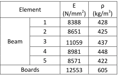
).Table 1 – Properties of the timber elements.
Element
E
(N/mm
2)
ρ
(kg/m
3)
Beam
1
8388
428
2
8651
425
3
11059
437
4
8981
448
5
8571
422
Boards
12553
605
The floor was supported by placing spruce boards with 120 mm width above each beam at tops, a condition that is not ideally a pin-pin boundary situation, but that will be much closer of what could be found in practice. (
Figure 1
a)).shapes remain unscaled. Although it is possible to obtain the scaled mode shapes by repeating the tests in the structure with a small mass at certain locations
[9
], only the basic procedure was released, which at least still offers a qualitative view of the mode shapes.The accelerometers positions were considered over the beams alignment, in order to get at least the low order modes (
Figure 1
b)). The mode shapes were then constructed from the measured points through a bi-cubic spline interpolation. The reference accelerometer was placed over beam 1 at 2/3 of its length, while the impact would be produced over the same beam but at 1/3 of the span, as this positions were expected not to be zero displacements in those first lower modes.After the dynamic test on the integral floor (i.e. with all the supports), the tests were repeated by removing one by one, in turn, the timber boards over the beams, simulating a total lack of the beam support. (
Figure 1
c)). [image:3.595.78.507.351.644.2]In order to match the experimental results, a Finite Element Model (FEM) of the timber floor (
Figure 1
d)) was developed with aid of SAP 2000 [10] considering frame elements to model the timber, link elements to model the nails and considering the beams pinned at both ends and the modal analysis was carried by considering an eigenvectors analysis that is suitable for an undamped free vibration analysis [11].Figure 1 – a) Timber floor; b) Test layout; c) Remove of support in test; d) Finite Element model of the floor.
RESULTS AND DISCUSSION
Table 2 – Natural undamped frequencies (Hz) of the first four mode shapes of the floor - numerical results.
Mode Integral Lack in support
1 2 3
1 20.33 11.41 18.11 18.27 2 20.41 20.39 20.39 20.33 3 26.31 24.20 25.20 23.44 4 32.90 31.41 29.49 30.77
Table 3 – Natural undamped frequencies (Hz) of the first four mode shapes of the floor - experimental results.
Mode Integral Lack in support
1 2 3
1 20.15 10.79 18.83 18.62
2 21.28 - 21.48 21.87
3 27.27 25.62 28.12 25.18 4 32.87 32.17 32.43 33.49
Table 4 – Damping coefficients (%) of the first four mode shapes of the floor - experimental results.
Mode Integral Lack in support
1 2 3
1 1.67 2.67 2.09 2.14
2 1.60 - 1.60 1.68
3 1.70 2.76 1.56 1.82
4 1.46 1.61 1.64 1.91
In a general way, in terms of frequencies and mode shapes, the experimental results match well the numerical ones. As could be seen in
Table 2
andTable 3
, the changes in frequencies are, as expected, not indicative of deterioration on supports as they do not differ substantially from the integral situation, exception made to the 1st mode on support 1’ situation where it decreases notably.The damping coefficients in the integral case are in the normal range for this type of construction, which usually present values around 1.5% to 2% [12][13]. However in all the lack support cases, the damping coefficients noticeable increase for the 1st mode for values higher than 2%; however the changes in the other modes, exception made to mode 3 on support 1’case, are not quite expressive.
From the analyzed dynamic parameters, is in the mode shapes that the differences are more expressive.
exception of the 3rd one. That fact is probably correlated with a less tightness at that support, which allowed higher displacements in that zone.
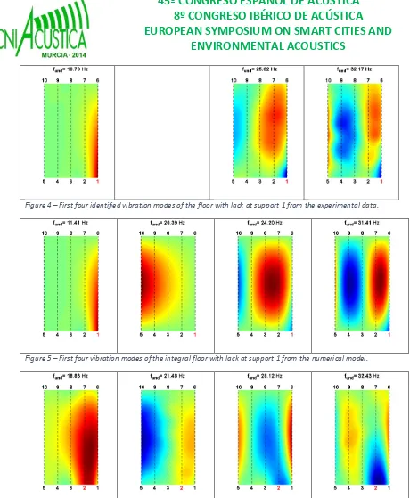
It should be noticed that the experimental mode shape corresponding to the 2nd vibration mode on the numerical model for the support 1 case (
Figure 4
andFigure 5
) is not present as the impact point was in a zero displacement node of that mode, as can be comproved by analyzing the corresponding mode shape of the FE model.In a general way, in the lack support situations the mode shapes clearly differ from the ones of the integral floor. In support 1’ case, with exception to 2nd mode, the displacement is higher near the retrieved support when compared to the other symmetric supports (5, 6 and 10). A similar situation occurs for support 2’ case (
Figure 6
andFigure 7
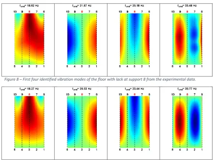
), comparing the displacement in that support with supports (4, 7 and 9). The same is observed for support 8 (Figure 8
andFigure 9
), comparing with support 3, however only in the 1st and 3rd modes. It is interesting to observe that in all the lack case, the 2nd mode shape, although it changes due to support lack, that change is not quite expressive, not allowing to the determination of the lack position. [image:5.595.76.515.355.686.2]It is observed that the inexistence of support at specific locations leads to substantially changes in the mode shapes, moreover higher relative displacements in the surrounding area appears in in some of the mode shapes when comparing to the integral floor situation. That fact allows the support lack location to be identified through a visual inspection of the modes.
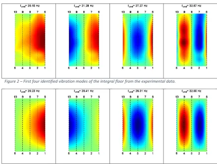
Figure 2 – First four identified vibration modes of the integral floor from the experimental data.
Figure 4 – First four identified vibration modes of the floor with lack at support 1 from the experimental data.
Figure 5 – First four vibration modes of the integral floor with lack at support 1 from the numerical model.
Figure 7 – First four vibration modes of the integral floor with lack at support 2 from the numerical model.
[image:7.595.76.517.302.633.2]Figure 8 – First four identified vibration modes of the floor with lack at support 8 from the experimental data.
Figure 9 – First four vibration modes of the integral floor with lack at support 8 from the numerical model.
CONCLUSIONS
The present paper revealed the results of an investigation about the dynamic changes on a timber floor due to simulated deterioration on supports. The analyzed parameters included the undamped natural frequencies, damping coefficients and mode shapes.
The results revealed that in extreme cases of deterioration of supports, the dynamic parameters change, in some cases the frequency and damping allows to detect that there is some problem, but is the mode shapes that the differences are more pronounced. The comparison between the mode shapes of the integral floor with the ones of the damaged situations, allow the detection of damage and in some of the modes it is possible to perceive the location of the support lacking.
However the results also show that even using glulam beams (with lower properties variation face to solid timber) the obtained mode shapes are in some modes quite different of the numerical ones, which makes difficult to develop a Finite Element model of an existent timber floor, whose properties are a priori unknown.
REFERENCES
[1]
Doebling S., Farrar C., Prime, M. A summary review of vibration-based damage identification Methods. Engineering Analysis Group Los Alamos National Laboratory Los Alamos, NM. 1998[2] Carden E., Fanning P. Vibration based condition monitoring: A review. Structural Health Monitoring. 2004.
[3] Stubbs N., Kim J., Topole K. Field verification of a nondestructive damage localization and severity estimation algorithm. Proceedings of the 1 3th International Modal Analysis
Conference: SPIE, pp. 210 – 218. 1995
[4] Pandey A., Biswas M . Damage detection in structures using changes in flexibility. Journal of Sound and Vibration 169 (1) (1994) 3 – 17. 1994.
[5] Carden E.P., Fanning P.J. An added mass identification algorithm based on frequency response functions. 2nd MIT Conference on Computational Fluid and Solid Mechanics, Boston, 17–20 June, Vol. 2, pp. 1880–1882, 2003.
[6] Choi F.C., Li J., Samali B., Crews K. Application of the modified damage index method to timber beams. Engineering Structures 30 (2008) 1124–1145. 2008
[7] Samali B., Li J., F. C. Choi F.C., Crews K. Application of the damage index method for plate-like structures to timber bridges Struct. Control Health Monit. 2010; 17:849–87. 2010.
[8] Brincker R., Ventura C.E., Andersen P. Damping Estimation by Frequency Domain Decomposition. Proceedings of the 19th International Modal Analysis Conference (IMAC), Kissimmee, Florida, pp.698-703, 2001.
[9] Parloo E., Verboven P., Guillaume P., Van Overmeire M. Sensitivity-Based Operational Mode Shape Normalization. Mechanical Systems and Signal Processing (2002) 16(5), 757– 767. 2002.
[10] Computers and Structures, Inc. CSI Analysis Reference Manual. Berkeley, California, USA July 2011
[11] Santos P., Martins C., Skinner J., Harris R., Dias A., Godinho L. Modal Frequencies of a Reinforced Timber-Concrete Composite Floor - Testing and Modeling (in submission to JSE ASCE)
[12] Chui Y. Evaluation of vibrational performance of light-weight wooden floors. Proc. Of the 1988 Int. Conference on Timber Eng. (1), 707–715. 1988.