Synthesis of a Specific Processor from a High Level Programming Language (Ada) Description Jean-Pierre Deschamps and Marcelo Tosini
Universidad Nacional del Centro de la Provincia de Buenos Aires Instituto de Sistemas - San Martín, 65 - 7000 Tandil - Argentina
E-mail: [email protected]
Summary: Ada 95 is proposed as an alternative solution for describing digital embedded systems. Two examples are presented. The first one is a Program-state Machine; its translation to an Ada program is based on the use of concurrent tasks, entry calls, protected objects and asynchronous transfer of control (ATC). The second one is a specific processor connected to a serial channel and to a system bus.
Key words: Embedded systems, Hardware/Software codesign, Hardware/Software cosimulation, Specific processors, Hardware description languages, Real time systems, Ada.
1. INTRODUCTION
The starting point of the development of an embedded system is a functional description. The final result is a set of interconnected components. Some of them are standard processors (Microprocessors, Digital Signal Processors) or Application Specific Instruction-Set Processors that execute a specific program; others are specific circuits (Application Specific Integrated Circuits, Field Programmable Gate Arrays) or commodity circuits (memories, device controllers). The translation of the initial description to a physical system roughly consists in (1) decomposing the system into a set of tasks that share global variables and interchange data through communication channels, (2) allocating processors (Microprocessor, DSP, ASIP, ASIC, FPGA) to the tasks, buses to the communication channels, memories to the global variables, (3) generating the application programs and synthesizing the specific circuits.
In order to synthesize a new integrated circuit (ASIC, FPGA) the traditional method starts from a specification in a hardware description language, generally VHDL or Verilog. After, high level synthesis and logic synthesis programs are used in order to obtain a net list of the circuit. Nevertheless, according to some authors (see for example R.K. Gupta and S.Y. Liao, 1997) an embedded system is easier to describe (at the beginning of the development work) if a high level programming language is used. The chosen language should allow to describe (1) concurrent tasks as well as the communication between them and (2) different behaviors with transitions between them defined by some external events (see for example D. Gajski et al., 1994). Another important point is the possibility to describe and simulate both the system and its environment.
Within the frame of the Asictan project1, Ada 95 was chosen as the initial specification language. Some reasons of using Ada are the following ones: (1) it has the above-mentioned characteristics (this point will be emphasized in the section 2 of this paper); (2) it is a standardized programming language and there exists a lot of development tools for generating and executing Ada programs; (3) VHDL inherited many of the Ada features: this point is important for the tasks to which specially designed processors (ASIC, FPGA) are allocated.
The proposed synthesis method is made up of the following steps:
(1) The initial description is an Ada program that defines the tasks that the system under development must perform as well as its environment. By compiling and executing this description on the host workstation the initial specification can be validated. An open question is whether to use all the Ada 95 constructs or to restrict oneself to a subset of the language. Presently the initial description is supposed to be made up of
• a set of non-hierarchical tasks,
• a set of protected objects that can be called up by any task,
• a main procedure in charge of the activation and linking of the tasks;
it is the so-called Single Ada Model (J.-P. Deschamps, 1998b). The tasks communicate through global variables, protected objects and messages (rendez-vous). Nevertheless these rather strong restrictions will be released in the future. Any way, as in any real time system, it is
1
desirable to avoid the use of recursive or reentrant procedure calls.
(2) The second step is the system partitioning. It consists in solving the tree above-mentioned allocation problems:
• some subsets of tasks may be executed by already existing processors (microprocessors, DSP, ASIP); other subsets of tasks should be executed by new specially designed (specific) processors (ASIC, FPGA);
• some subsets of global variables and protected objects may be implemented by standard shared resources (random access memories, queues, interface circuits); other subsets should be integrated within application specific circuits;
• buses, and possibly bus arbiters, must be allocated to the communication channels between tasks (messages) and between tasks and shared resources.
These allocation problems still form an important field of research. Their solution can be based on mathematical methods (graph theory, linear programming) or on simulation. Several allocation algorithms are described in G. De Micheli, 1994, D. Gajski et al., 1994, R.K. Gupta, 1995.
(3) The next step is the programming of the programmable processors (microprocessors, DSP, ASIP) and the synthesis of the specific circuits (specific processors, non-standard shared resources). As regards the specific processors the synthesis is divided into several substeps: • The description of the corresponding tasks (an Ada program) is translated to an intermediate
form (an assembly-like program). Actually it is another Ada program based on procedures and type definitions stored in two packages that constitute the Ada/Lep language definition (M. Tosini y J.-P. Deschamps, 1998). The communication channels are still modeled by means of global variables, protected object calls and message passing.
• The Ada/Lep program is converted into an equivalent microprogram (a VHDL-like program). Once again it is an Ada program based on the two above-mentioned packages. The communication protocols must have been previously defined.
• The VHDL-like description can be translated to a true VHDL description that could serve as an entry point for some logic synthesis program. Nevertheless another possibility is the direct synthesis of the data path, the microprogram sequence controller and the microinstruction decoder, and the generation of the microprogram memory contents.
The main goal of this paper is the description, through a simple but complete example, of this specific processor synthesis method. Observe that, thanks to the use of the same language (Ada) at the three description levels (initial specification, assembly-like program, VHDL-like program), the whole system and its environment can be simulated with three different models of the specific processor. In other words, the hardware/software cosimulation is performed by using a common language (Ada) for the description of both the programmable and the specific processors.
In the section 2 of this paper the claim that Ada 95 is a suitable language for describing embedded systems is justified by describing the translation of a Program-state machine specification to an Ada program. In the following sections a complete example of a specific processor synthesis is presented: section 3 states the problem; the first description level (initial specification) is described in section 4; section 5 is a short introduction to the Ada/Lep language; the second description level (assembly-like program) is described in section 6, and the third one (VHDL-like program) in section 7. A complete description of Ada 95 can be found in J. Barnes, 1996.
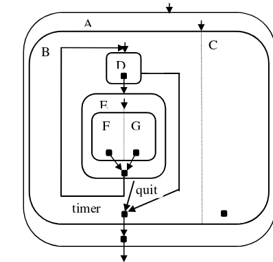
starts. When the execution of both programs terminates and when the condition timer is true the control is transferred back to D. If the condition quit becomes true, the running program(s) associated with D, or with F and G, are interrupted; the state B finishes and consequently the program associated with the state C is interrupted.
In order to describe and simulate the machine, an Ada task is associated with every state. Each of them includes the declaration of an entry start and of a global boolean variable end_task. As an example, the task F of figure 1, associated with a leaf state, is declared and defined as follows:
task F is entry start; end F; end_F: boolean := false; task body F is
begin loop
accept start;
<program associated with F> end_F := true;
end loop; end F;
For describing composite states, one or several entry calls must be performed. As an example, the concurrent composite state E is described by the following task (the quit condition is supposed to be false)
task body E is begin loop
accept start; F.start; G.start; loop
if end_F and end_G then end_F := false; end_G := false; end_E := true; exit; end if; end loop;
end loop; end E;
and the sequential composite state B by the following one
task body B is begin
accept start; D.start; loop
if exception_D or exception_E then end_B := true; exit; end if; end loop;
end B;
(the condition exception_D(E) becomes true if the external event quit happens during the execution of D(E)).
A
B C
D
E
F G
qu
[image:3.612.292.491.130.321.2]quit timer
A protected object, the type of which is interruption, is associated with every task that could be interrupted, either explicitly when some event happens - it is the case of the tasks D and E when the condition quit becomes true - or implicitly when other taks are interrupted - it is the case of the task C when the task B finishes:
protected type interruption is
procedure set_flag; procedure clear_flag; entry wait_flag; private flag: boolean := false;
end interruption;
interruption_D, interruption_E, interruption_C: interruption;
As an example, the state D is described as follows:
exception_D: boolean := false; task body D is
begin loop accept start;
interruption_D.clear_flag; select interruption_D.wait_flag;
exception_D := true; then abort
<program associated with D; it includes the sentence “ timer := false;”> end_D := true;
end select; end loop; end D;
Observe that the interruption mechanism is based on the Asynchronous Transfer of Control (ATC) construction. It is similar to the do ... watching construction of the Esterel language (F. Boussinot and R. De Simone, 1991).
The linking of the tasks is under the control of the main program:
procedure figure_1 is begin
A.start; loop
if end_A then exit; elsif end_D then end_D := false; E.start; elsif end_E and timer then end_E := false; D.start; end if; end loop;
end figure_1;
An additional task control simulates the system environment, that is to say, it generates the timer and quit conditions. For example:
task body control is begin
delay 2.0; timer := true; delay 2.0; timer := true; delay 0.25;
quit := true; interruption_D.set_flag; interruption_E.set_flag; delay 2.0; end control;
A complete description of the Program-state machine of figure 1 is given in J.-P. Deschamps, 1998a.
Observe that the tasks that are associated with non-leaf states only serve to control part of the linking of the tasks; they do not process data. A simple transformation (expansion) allows to eliminate them. The new description contains
• a set of tasks that actually process data,
• a main procedure that control the linking of the tasks.
It is the so-called Single Ada Model (J.-P. Deschamps, 1998b). As an example, the machine of figure 1 could be described as follows:
accept start;
<monitoring program> end C;
task body D is begin loop
accept start;
<data acquistion and timer setting program> end_D := true;
end loop; end D;
task body F is ... <data processing 1> ... end_F; task body G is ... <data processing 2> ... end_G; procedure figure_1 is
begin
D.start; C.start; loop
if quit then abort C; abort D; abort F; abort G; exit; elsif end_D then end_D := false; F.start; G.start;
elsif end_F and end_G and timer then end_F := false; end_G := false; D.start; end if; end loop;
end figure_1;
(in this example it is not necessary to use the ATC construct: when the event quit happens all the running programs are aborted).
The synchronization and communication between tasks can be performed by using global variables, protected objects and messages. As an example, suppose that the task F of figure 1 communicates with the tasks D and C through a protected object main_memory
protected type memory is
procedure write (address: in address_type; data: in data_type); procedure read (address: in address_type; data: out data_type); private ... end memory;
main_memory: memory;
and that the tasks F and G communicate between themselves through messages G_to_F and F_to_G. The structure of the task F could be the following one (G is supposed to be a coprocessor of F):
task body F is x1, x2: address_type; y1, y2, y3, y4: data_type; ... begin loop
accept start;
-- F gets the value of y1 that has been previously stored at address x1 by D main_memory.read (x1, y1);
<F processes y1 and generates y2> -- F sends y2 to G
G.F_to_G (y2); -- F receives y3 from G
accept G_to_F (data: in data_type) do y3 := data; end G_to_F; <F processes y3 and generates y4>
-- F stores the value of y4 at address x2; further on it will be read by C main_memory.write (x2, y4);
end_F := true; end loop; end_F;
In this example, the three above-mentioned allocation problems are stated as follows: • allocate processors to the task C, D, F and G;
• allocate a shared resource (a memory) to the protected object main_memory;
• allocate buses to the communication channels: C to main_memory, main_memory to F, F to G, G to F, F to main_memory, main_memory to C.
3.
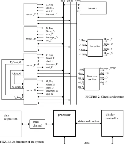
DEFINITION OF A SPECIFIC PROCESSORA second example will now be presented. It consists in synthesizing a specific processor that computes the greatest common divisor of two 16-bit natural numbers. It is part of a system the structure of which is shown in figure 3: the operands are captured by a remote circuit that communicates with the processor through a serial channel; the result is sent to a display controller through the system data bus. The operations are performed in the following way: • the data acquisition circuit periodically transmits the operands x and y to the processor; • every time that it receives new operands x and y, the processor calculates z = gcd(x, y) and
sends the result z to the display controller;
• whenever the display controller receives a new value of z, it publishes it.
The greatest common divisor calculation is based on a reiterative use of the following properties:
if x>y then gcd(x, y) = gcd(x-y, y); if x<y then gcd (x, y) = gcd(x, y-x); if x=y then gcd(x, y) = x.
display controller processor
status and control
data data
acquisition
serial channel
FIGURE 3: Structure of the system
Grant_C status
contro l data
interrupt_CDFG
start_FG
start_D
start_C C_Req
F_Grant_G
G_Req_F G_Grant_F F_Req_G
Grant_C C_Req
start_C interrupt_C
D_Req Grant_D start_D interrupt_D end_D
F_Req Grant_F start_F interrupt_F end_F
G_Req Grant_G start_G interrupt_G end_G proces._C
proces._D
proces._F
proces._G
memory
D_Req
F_Req
G_Req
Grant_D
Grant_F
Grant_G bus arbiter
quit
timer
end_D
end_F
end_G
[image:6.612.108.513.263.733.2]finite state machine
4. INITIAL SPECIFICATION
In order to simulate the processor and its environment it is necessary to have a model of the data acquisition circuit, the serial channel, the processor itself and the display controller.
4.1 Model of the serial channel
The functional model of the serial channel is made up of two packages uart and line. The first one describes the protected type interface_IO; it allows to instantiate objects accessible through four procedure calls
• write: it writes a byte into the transmitter register register_T belonging to the private part of the object;
• read: it reads a byte from the receiver register register_R belonging to the private part of the object;
• state_T: it returns a boolean value that describes the state of the transmitter register (true: it is empty; false: it contains a byte that still must be transmitted);
• state_R: it returns a boolean value that describes the state of the receiver register (true: it contains a byte that can be read; false: it is empty),
and through two entry calls
• get_out: if the transmitter register contains a byte, it is transmitted through the transmit line TxD; as a result, the transmitter register gets empty;
• put_in: if the receiver register is empty, a new byte is received from the receive line RxD; as a result, the receiver register contains a byte:
subtype byte is integer range 0 .. 255; protected type interface_IO is
procedure write (data: in byte); procedure read (data: out byte);
procedure state_T (state: out boolean); procedure state_R (state: out boolean); entry get_out (data: out byte); entry put_in (data: in byte);
private ... end interface_IO;
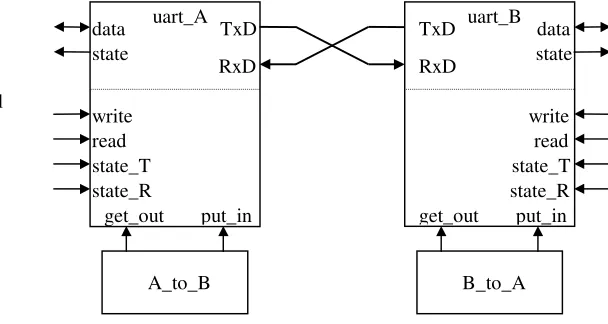
The complete serial channel is made up of two interface_IO-type objects uart_A and uart_B and of two tasks A_to_B and B_to_A that simulate the transmit/receive mechanism (figure 4). As an example, if the uart_A transmitter register contains a byte (this condition is the barrier of the get_out entry call of uart_A) then the task A_to_B gets the byte out of the register; after, if the uart_B receiver register is empty (this condition is the barrier of the put_in entry call of uart_B), the task A_to_B puts the byte into the register:
task body A_to_B is
data: byte; begin loop
uart_A.get_out (data); delay 0.5;
uart_B.put_in (data); end loop; end A_to_B;
4.2 Model of the data acquisition circuit
data uart_A uart_B
write read state_T state_R state
TxD
RxD
data
write read state_T state_R state TxD
RxD
put_in
put_in get_out
get_out
[image:7.612.204.508.474.636.2]A_to_B B_to_A
FIGURE 4: Serial
The task acquisition gets the operands x and y every 10 seconds from the keyboard of the host workstation, splits them up into two bytes (x = (x1, x0), y = (y1, y0)) and sends them to the processor through the serial channel:
subtype oper is integer range 0 .. 65535; task body acquisition is
x, y: oper; x1, x0, y1, y0: byte;
CR: character; state: boolean := false; begin loop
put ("x = "); get (x); get (CR); put ("y = "); get (y); get (CR);
x1 := x / 256; x0 := x - (256 * x1); y1 := y / 256; y0 := y - (256 * y1); -- transmit x1 to the serial channel
uart_A.state_T (state); while not (state) loop uart_A.state_T (state); end loop; uart_A.write (x1);
<same operations for x0, y1, y0> delay 10.0;
end loop; end acquisition;
4.3 Model of the processor
The corresponding task gets the operands x = (x1, x0) and y = (y1, y0) from the serial channel, calculates z = gcd(x, y) and transmits the result to the display controller by means of a message result:
task body processor is
x, y, z: oper; x1, x0, y1, y0: byte; state: boolean := false; begin loop
-- receive x1 from the serial channel
uart_B.state_R (state); while not (state) loop uart_B.state_R (state); end loop; uart_B.read (x1);
<same operations for x0, y1, y0>
x := x0 + (256 * x1); y := y0 + (256 * y1);
while x /= y loop if x >= y then x := x - y; else y := y - x; end if; end loop; z := x; display.result (z);
end loop; end processor;
4.4 Model of the display controller
This task accepts the message generated by the processor and displays the result z on the host workstation monitor:
task body display is z: oper;
begin loop
accept result (a: in oper) do z := a; end result; put ("gcd (x, y) = "); put (z); New_Line; end loop; end display;
The complete functional model is described in J.-P. Deschamps, 1997. It has been compiled and executed (Gnat compiler, New York university), and proved to be an accurate initial specification of the system.
5. THE ADA/LEP LANGUAGE
register R1, a 10-bit register R2 and an 8-bit register R3; the debug_info flag is put to true in order to enable the debugging facilities included in the alu package:
package my_alu is new alu (word_width => 5, debug_info => true); use my_alu; R1: register (one); R2: register (two); R3: register (0 .. 7);
A set of procedures are defined within the alu package; they correspond to the arithmetic-and-logic and input-output instructions of the hypothetical processors. For example:
DO_IN (a: out register; b: in io_port); DO_OUT (a: out io_port; b: in register);
DO_ADD (a: out register; b: in register; c: in register); DO_MUL (a: out register; b: in register; c: in register);
DO_DIV (a: out register; b: in register; c: in register; k: in integer); etc.
With these procedures it is possible to write assembly-like instructions. For example:
DO_IN (R1, PORT2); R1 <= PORT2 DO_ADD (R1, R2, R3); R1 <= R2 + R3 DO_DIV (R1, R2, R3, 3); R1 <= R2/R3 * 23
The jumps and branches are programmed with the GOTO and IF boolean_expression GOTO instructions of Ada. Some predefined boolean variables (flags) are included within the alu package: inp_1_sign, inp_1_zero, inp_1_odd, inp_1_even, inp_2_sign, inp_2_zero, inp_2_odd, inp_2_even, out_sign, out_zero, out_odd, out_even, carry, overflow. They all refer to the operands (inp_1, inp_2) and to the result (out) of the latest executed arithmetic-and-logic instruction.
The subroutines calls are programmed with the procedure calls of Ada. For example:
procedure square_root (a: out register; b: in register) is begin ... end square_root; square_root (R1, R2);
The protected objects must be called through io_port-type or bit-type variables. For example, suppose that the protected type memory has been defined
protected type memory is
procedure memory_access (address: in io_port; data: in out io_port; read_write: in bit); private ... end memory;
and that an object a_memory has been instantiated
a_memory: memory;
then the memory-read and memory-write operations can be programmed as follows:
a_memory (address_bus, data_bus, 0); data_bus <= M (address_bus) a_memory (address_bus, data_bus, 1); M (address_bus) <= data_bus
where address_bus and data_bus have been declared as io_port-type variables.
6. ASSEMBLY CODE
From now on all the data handled by the processor must be io_port-type, register-type or bit-type variables, so that the serial channel model must be slightly modified:
protected type interface_IO is
procedure write (data: in io_port); procedure read (data: out io_port); procedure state_TR (state: out io_port);
the state of the transmitter register is given by state(0) and the state of the receiver register by state(1).
At this point of the synthesis process some decisions must be taken concerning the processor architecture:
• An 8-bit wide data path will be used:
package processor_alu is new alu (8, true); use processor_alu;
• The processor is connected to the serial channel through an 8-bit bus serial_bus and to the display controller through a 16-bit bus data_bus:
serial_bus: io_port (one); data_bus: io_port (two);
Within the Ada/Lep program the following variables will be used:
• four 16-bit variables that store the operands (xx, yy), the final result (zz) and an intermediate result (accumulator);
• five 8-bit variables that store the operand bytes (xx1, xx0, yy1, yy0) and the serial channel status register contents (state).
The Ada/Lep description of the processor is the following one:
task body processor is
serial_bus: io_port (one); data_bus: io_port (two); accumulator, xx, yy: register (two);
xx1, xx0, yy1, yy0, state: register (one); begin
-- read xx1, xx0, yy1, yy0 from the serial channel <<label_1>> uart_B.state_TR (serial_bus); DO_IN (state, serial_bus);
IF state(1) = 0 THEN GOTO label_1; END IF; uart_B.read (serial_bus);
DO_IN (xx1, serial_bus);
<same operations for xx0, yy1, yy0> -- concatenate xx1 with xx0 and yy1 with yy0 DO_CONCAT (xx, xx1, xx0);
DO_CONCAT (yy, yy1, yy0); -- calculate the result zz
<<label_5>> DO_SUB (accumulator, xx, yy); IF out_zero THEN GOTO label_7; END IF; IF carry THEN GOTO label_6; END IF; DO_SUB (xx, xx, yy);
GOTO label_5;
<<label_6>> DO_SUB (yy, yy, xx); GOTO label_5;
<<label_7>> DO_OUT (data_bus, xx); -- transmit the result zz to the display controller display.result (data_bus);
GOTO label_1; end processor;
In order to simulate the whole system it is necessary to slightly modify the tasks acquisition and display (io_port-type or register-type variables instead of integer-type variables). The complete model is described in J.-P. Deschamps, 1997.
7. VHDL CODE
First, the processor data path architecture is defined. The following conclusions are drawn from the Ada/Lep program analysis:
• The arithmetic-and-logic unit must be able to execute the following operations: - subtraction with initial carry equal to 0 (first part of DO_SUB);
- subtraction with initial carry generated by the previous instruction execution (second part of DO_SUB);
It must generate two flags, carry and out_zero, the values of which depend on the previous instruction result (DO_SUB (accumulator, xx, yy)).
• The registers are allocated to the program variables in the following way: R0 => state; R1 => xx1, zz1; R2 => xx0, zz0; R3 => yy1; R4 => yy0.
It is not necessary to allocate a register to the variable accumulator that is never used as an operand (the DO_SUB (accumulator, xx, yy) instruction only serves to update the flag values).
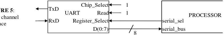
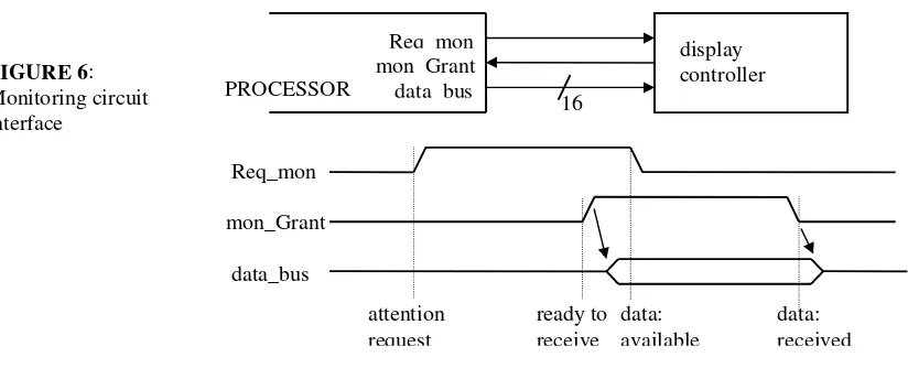
After, the communication protocols must be defined. The communication with the serial channel is shown in figure 5. It uses a single control variable serial_sel (0: status register selection; 1: receiver register selection). The communication with the display controller is shown in figure 6. It uses two control variables Req_mon (request signal) and mon_Grant (acknowledge signal).
Once again the serial channel model must be slightly modified in order to implement the chosen communication protocol:
protected type interface_IO is
procedure write (data: in io_port); procedure read (sel: in bit; data: out io_port); entry get_out (data: out io_port); entry put_in (data: in io_port);
private ... end interface_IO;
The VHDL-like description is the following one:
data_bus: io_port (0 .. 15); Req_mon: bit; mon_Grant: bit; task body processor is
serial_bus: io_port (0 .. 7); serial_sel, cy, ze: bit;
inp_latch, R0, R1, R2, R3, R4, prov: register (0 .. 7); out_latch: register (0 .. 15); subtype number is integer range 0 .. 40; cp: number;
procedure subtract (a: out register; b, c: in register) is
<this procedure calculates a = b - c - cy, and updates cy and ze> end subtract;
begin
cp := 0; Req_mon := 0; loop case cp is
-- read R1 = xx1, R2 = xx0, R3 = yy1, R4 = yy0 from the serial channel when 0 => serial_sel := 0; uart_B.read(serial_sel, serial_bus);
for i in 0 .. 7 loop inp_latch(i) := serial_bus(i); end loop; cp := cp+1; when 1 => R0 := inp_latch; cp := cp+1;
when 2 => if R0(1) = 0 then cp := 0; else cp := cp+1; end if; when 3 => serial_sel := 1; uart_B.read(serial_sel, serial_bus);
for i in 0 .. 7 loop inp_latch(i) := serial_bus(i); end loop; cp := cp+1; when 4 => R1 := inp_latch; cp := cp+1;
<same operations for R2, R3, R4> -- calculate the result R1 = zz1, R2 = zz0 when 20 => cy := 0; ze := 1; cp := cp+1; when 21 => subtract (prov, R2, R4); cp := cp+1; when 22 => subtract (prov, R1, R3); cp := cp+1;
when 23 => if ze = 1 then cp := 32; else cp := cp+1; end if; when 24 => if cy = 1 then cp := 28; else cp := cp+1; end if; when 25 => subtract (R2, R2, R4); cp := cp+1;
when 26 => subtract (R1, R1, R3); cp := cp+1; Chip_Select 1 TxD
UART Read 1
serial_sel Register_Select
RxD
serial_bus D(0:7)
8
[image:11.612.123.514.246.308.2]PROCESSOR
FIGURE 5:
when 27 => cp := 20;
when 28 => cy := 0; cp := cp+1;
when 29 => subtract (R4, R4, R2); cp := cp+1; when 30 => subtract (R3, R3, R1); cp := cp+1; when 31 => cp := 20;
-- transmit the result to the display controller
when 32 => for i in 0 .. 7 loop out_latch(i) := R1(i); end loop; cp := cp+1; when 33 => for i in 0 .. 7 loop out_latch(i+8) := R2(i); end loop; cp := cp+1; when 34 => Req_mon := 1; cp := cp+1;
when 35 => if mon_Grant = 0 then cp := 35; else cp := cp+1; end if;
when 36 => for i in 0 .. 15 loop data_bus(i) := out_latch(i); end loop; cp := cp+1; when 37 => Req_mon := 0; cp := cp+1;
when 38 => if mon_Grant = 1 then cp := 38; else cp := cp+1; end if; when 39 => data_bus :=(0,0,0,0,0,0,0,0,0,0,0,0,0,0,0,0); cp := cp+1; when 40 => cp := 0;
end case; end loop; end processor;
In order to simulate the whole system it is necessary to modify the tasks acquisition (communication with the modified serial channel model) and display (communication protocol implementation). The complete model is described in J.-P. Deschamps, 1997.
It remains to synthesize the circuit, that is to generate its nets list for some ASIC or FPGA technology. This can be done in (at least) two ways. A first method consists in generating the circuit description directly from the Ada/VHDL-like program. The circuit is made up of a data path and a microprogrammed control unit. The circuit generation work mainly consists in • decomposing the data path and the control units in blocks such as: the input and output
ports, the arithmetic-and-logic unit(s), the register bank(s), the microprogram memory, the microprogram sequencer, the microoperation decoder;
• choosing a synchronization scheme; • choosing a microinstruction format;
• synthesizing part of the blocks; for instance: the ports, the arithmetic-and-logic unit, the microprogram sequencer, the microoperation decoder; for that purpose a library of parameterized VHDL models and a logic synthesis program should be used;
• generating the microprogram memory contents;
• compiling the remaining blocks; for instance: the register bank (dual port RAM compiler), the microprogram memory (ROM compiler).
Another method would consist in (1) translating the Ada/VHDL-like description to a true VHDL program and (2) synthesizing the VHDL description. The translation to a VHDL description is relatively easy. It mainly consists in
• adding a synchronization scheme;
• adapting the Ada/VHDL-like program to the VHDL syntax and semantics rules.
In the case of the current example the chosen synchronization scheme is the following one: all the internal variables, that is inp_latch, R0 to R4, out_latch, cy, ze, and cp, are updated on the falling edge of a synchronization signal clk. For that purpose two signals x and x_in, and a guarded assignment
x <= guarded x_in;
are associated with every internal variable x; the guard condition is the falling edge of clk. The VHDL code is the following one:
entity mcd_mic is
port (serial_bus: in qit_vector(0 to 7); serial_sel:out qit; data_bus: out qit_vector(0 to 15); Req_mon: out qit; mon_Grant: in qit; reset, clk: in qit); end mcd_mic;
architecture ada of mcd_mic is
signal inp_latch, inp_latch_in, R0, R0_in, R1, R1_in, R2, R2_in, R3, R3_in, R4, R4_in: qit_vector(0 to 7);
signal out_latch, out_latch_in: qit_vector(0 to 15); signal cy, cy_in, ze, ze_in: qit; subtype number is integer range 0 to 40; signal cp, cp_in: number;
procedure subtract (signal a: out qit_vector(0 to 7); b, c: in qit_vector(0 to 7); signal cy_in, ze_in: out qit;
signal cy, ze: in qit) is .... end subtract; begin
block_label: block (clk = '0' and not clk'stable) begin
inp_latch <= guarded inp_latch_in; R0 <= guarded R0_in; R1 <= guarded R1_in; R2 <= guarded R2_in; R3 <= guarded R3_in; R4 <= guarded R4_in;
out_latch <= guarded out_latch_in; cy <= guarded cy_in; ze <= guarded ze_in; cp <= guarded cp_in when reset = '0' else 0;
end block block_label;
process (serial_bus, mon_Grant, cp) begin case cp is
when 0 => serial_sel <= '0'; inp_latch_in <= serial_bus; data_bus <= "zzzzzzzzzzzzzzzz"; Req_mon <= '0'; cp_in <= cp+1;
when 1 => R0_in <= inp_latch; cp_in <= cp+1;
when 2 => if R0(1) = '0' then cp_in <= 0; else cp_in <= cp+1; end if; when 3 => serial_sel <= '1'; inp_latch_in <= serial_bus; cp_in <= cp+1; when 4 => R1_in <= inp_latch; cp_in <= cp+1;
....
when 20 => cy_in <= '0'; ze_in <= '1'; cp_in <= cp+1;
when 21 => subtract (prov, R2, R4, cy_in, ze_in, cy, ze); cp_in <= cp+1; when 22 => subtract (prov, R1, R3, cy_in, ze_in, cy, ze); cp_in <= cp+1; when 23 => if ze = '1' then cp_in <= 32; else cp_in <= cp+1; end if; when 24 => if cy = '1' then cp_in <= 28; else cp_in <= cp+1; end if; when 25 => subtract (R2_in, R2, R4, cy_in, ze_in, cy, ze); cp_in <= cp+1; when 26 => subtract (R1_in, R1, R3, cy_in, ze_in, cy, ze); cp_in <= cp+1; when 27 => cp_in <= 20;
when 28 => cy_in <= '0'; cp_in <= cp+1;
when 29 => subtract (R4_in, R4, R2, cy_in, ze_in, cy, ze); cp_in <= cp+1; when 30 => subtract (R3_in, R3, R1, cy_in, ze_in, cy, ze); cp_in <= cp+1; when 31 => cp_in <= 20;
when 32 => for i in 0 to 7 loop out_latch_in(i) <= R1(i); end loop; cp_in <= cp+1; when 33 => for i in 0 to 7 loop out_latch_in(i+8) <= R2(i); end loop; cp_in <= cp+1; when 34 => Req_mon <= '1'; cp_in <= cp+1;
when 35 => if mon_Grant = '0' then cp_in <= 35; else cp_in <= cp+1; end if;
when 36 => for i in 0 to 15 loop data_bus(i) <= out_latch(i); end loop; cp_in <= cp+1; when 37 => Req_mon <= '0'; cp_in <= cp+1;
when 38 => if mon_Grant = '1' then cp_in <= 38; else cp_in <= cp+1; end if; when 39 => data_bus <= "zzzzzzzzzzzzzzzz"; cp_in <= cp+1;
when 40 => cp_in <= 0; end case; end process; end ada;
8. CONCLUSIONS
The main conclusion of this work is that Ada is a convenient language for specifying digital embedded systems. Two examples were presented:
display controller PROCESSOR
Req_mon mon_Grant data_bus
16
Req_mon
mon_Grant
data_bus
data: received data:
available ready to
receive attention
[image:13.612.115.527.526.693.2]request
FIGURE 6:
• The first one is a Program-state Machine. The translation to an Ada program is rather simple thanks to the use of concurrent tasks, entry calls, protected objects and asynchronous transfer of control. The advantage of using Ada, instead of a special purpose language, is the availability of a lot of development tools for generating and executing Ada programs. Furthermore, the initial specification of the tasks that will eventually be implemented in a standard processor is a program that can be compiled for that processor.
• The second example is a specific processor connected to an 8-bit serial channel and to a 16-bit system bus. Three description styles were used: initial specification, assembly-like program, VHDL-like description. They correspond to three steps of a classical top-down design methodology. Furthermore the ability of Ada to describe interface and peripheral circuits was demonstrated. An advantage of Ada is its similarity with VHDL: the translation of the VHDL-like description to a true VHDL program is straightforward.
Within the frame of the Asictan project, the main research activities are the following ones: • Incorporation of performance estimation facilities (metrics) within the Ada models, in order
to give the designer the ability to compare different system partitions and resource allocations and bindings.
• Selection and generation of high level synthesis tools allowing to directly translate an Ada/VHDL-like description to a circuit architecture.
• Prototyping of specific processors. A fast prototyping tool is under development, based on the following strategy: an Ada program, that describes the whole system (except the specific processor) and its environment, is executed on the host workstation; this program communicates with an FPGA-based prototype of the specific processor through an input-output board.
• Development of an Ada retargetable compiler (see for example C. Liem, 1997) that allows to translate an Ada program (with some restrictions) to either an assembly program for some standard processors or to a program using some subset of the complete Ada/Lep instruction set.
REFERENCES
J. Barnes (1996), Programming in Ada 95, Addison-Wesley, 1996.
G. De Micheli (1994), Synthesis and Optimization of Digital Circuits, McGraw-Hill, 1994. J.-P. Deschamps (1998a), “Descripción en Ada de Sistemas Digitales”, Cuarto Workshop IBERCHIP, Mar del Plata, 11 - 13 de Marzo de 1998.
J.-P. Deschamps (1998b), “Materialización de Sistemas Descritos por un Modelo Ada Simple”, Cuarto Workshop IBERCHIP, Mar del Plata, 11 - 13 de Marzo de 1998.
F. Boussinot and R. De Simone (1991), “The ESTEREL Language”, Proceedings of the IEEE, Vol. 79, No. 9, pp. 1293 - 1304, September 1991.
D. Gajski, F. Vahid, S. Narayan and J. Gong (1994), Specification and Design of Embedded Systems, Prentice Hall, 1994.
R.K. Gupta (1995), Co-Synthesis of Hardware and Software for Digital Embedded Systems, Kluwer Academic Publishers, 1995.
R.K. Gupta and S.Y. Liao (1997), “Using a Programming Language for Digital System Design”, IEEE Design & Test of Computers, April - June 1997, pp. 72 - 80.
C. Liem (1997), Retargetable Compilers for Embedded Core Processors, Kluwer Academic Publishers, 1997.
M. Tosini y J.-P. Deschamps (1998), “ADA/LEP - Un Lenguaje de Especificación de Procesadores”, Cuarto Workshop IBERCHIP, Mar del Plata, 11 - 13 de Marzo de 1998.
J-P Deschamps (1997),”Síntesis de un Sistema Digital a partir de una Descripción en Ada”,ISISTAN, Reporte Técnico TR034, 1997.