SPATIAL PATTERNS OF THE TRANSIENT ULTRASONIC FIELD
RADIATED BY A DUAL-TRANSDUCER NDE PROBE
PACS REFERENCES: 43.35, 43.38, 43.20
Azbaid, Abdelhalim; Ramos, Antonio; San Emeterio, Jose Luis; Sanz, Pedro Tomás Dpto. Señales, Sistemas y Tecnologías Ultrasónicas (Insto. Acústica) - CSIC
Serrano 144, 28006 Madrid Spain
Tel.: 34-91-5618806 Fax: 34-91-4117651
e-mail: [email protected]
ABSTRACT
In some Non Destructive Evaluation applications, a particular type of probe having two separate transducer elements, for emission and reception purposes, is used looking for a practical improvement in sub-surface flaw detection and lateral resolution. These probes (named dual-element transducers or twin T/R probes) are intended for an operation in which only one of the transducers is specifically radiating an ultrasonic field. In this work a T/R NDE ultrasonic probe is investigated when it is radiating into water. A preliminary analysis to check possible radiation problems associated with such probe, when it is non-conventionally operated in order to actuate as two similar emitters, is here presented. Experimental plots of field patterns generated in transient regime by both transducers, in separated and simultaneous way, are gate-detected and comparatively evaluated. Some differences between cross-sectional and longitudinal patterns produced by the two twin transducers contained inside the T/R probe are evidenced. Some possible origins of these probe asymmetries are commented.
INTRODUCTION
A specific kind of piezoelectric probe usually named “dual-element transducers” or well “twin T/R probes” (depending on different manufacturers) is frequently used in industrial applications developed in the area of the non destructive testing [1-2]. The utilisation of these special probes, radiating ultrasonic pulses in the Megahertz range, is often chosen in those ultrasonic inspections where an important improvement in sub-surface flaw detection and / or lateral resolution is needed. In fact, the use of these probes provides a very good near resolution with a small focal depth. These T/R configurations are generally applied to make a vertical inspection over the pieces under testing by means of longitudinal ultrasonic waves.
These dual probes are composed of two separate transducer elements housed in the same case, one to launch the emission pulse and the other for reception purposes. Most of theses probes incorporates a plastic delay line (perspex) in front of the piezoelectric ceramics for coupling and protection purposes. The potential T/R element cross-talk, in this type of dual-transducer structures, is limited by the incorporation of acoustical and electrical shielding into the common housing [3].
stage on the received signals. This is relevant for detection of small flaws located very close to the external surface because, in other case, the testing indications could remain buried in the noise signals induced, through electric and electromagnetic ways, by the voltage high-frequency driving spikes coming from the pulser.
A special mode of operation of such dual-transducers probes, in which the two internal elements could be operated as an emitter, is intended in [4] for a better flaws insonification. As a previous study, to confirm the viability of such operation mode, a checking of some ultrasonic field aspects in transient driving conditions must be made under this special transmitting regime. In addition, it is interesting to check the desirable similitude of the twin transducers contained into such type of dual ultrasonic probes. With this checking purpose, a commercial T/R NDE ultrasonic probe, is experimentally investigated in this paper, when it is radiating into a water tank. In particular, different transversal and longitudinal spatial patterns of the transient ultrasonic field, radiated by each one of the two transducers contained in the selected NDE probe, have been measured. Two differents driving situations are considered: transducer excitations at different times, and probe drivings performed in a simultaneous way. Some differences between the plots of each one of the internal transducers, in the very near and far field zones, will be shown and analysed along the next sections.
ANALYSIS OF SOME ULTRASONIC FIELD PATTERNS RADIATED BY A TWIN T/R NDE PROBE
Two types of scans has been performed to study the spatial field distribution of the selected T/R probe, under an impulsive excitation regime: transversal scans in a plane parallel and very close to the transducer radiating surface; and longitudinal scans performed in planes perpendicular to the common transducers boundary (probe diameter). An experimental arrangement has been disposed in order to make an accurate detection of the transient ultrasonic waves.
Experimental Set-up used for transient field measurements
In order to detect and plot the spatial distributions of the transient acoustic field produced by the dual-transducer probe, an experimental set-up has been arranged, including an automated water tank, a control electronic system to perform an accurate mechanical scanning with a needle-type broadband hydrophone, pulser-receiver-amplifier electronics suitable to obtain a good signal to noise ratio, an acquisition / A-D converter system, and a gated detector to acquire the peak values of the field signal envelopes during the spatial scanning.
We have used an own-designed HV spike generator [5] for the untuned driving of the two broad band transducers included in the NDE dual-probe analysed. Its pulse repetition frequency was synchronised to the gated detector in the reception stage.
The plots of the radiated acoustic field, over planes parallel and perpendicular to the probe emitting surface, were obtained by performing successive 2-D raster scannings in the automated water-tank with a step resolution of 20 µm in the mechanical displacements. All the electronic controlling the mechanical scannings was synchronised with the ultrasonic transceiver stage, and a pulse repetition rate relatively high was generated in order to allow a fast scanning.
The selected broad band hydrophone [6], based in a small 0.6 mm PZT piezoelectric element, has a quasi-plane frequency response in the considered megahertz range, with a sensitivity of around 0.1 µvolt / Pascal.
Transversal Scans Measurements Close to the Transducer Aperture
A transverse planar scanning was performed very close to the emitting surfaces of the probe, in order to analyse the initially radiated acoustic pattern by each transducer element. In all the measured patterns, a field of (± 10) x (± 10) mm was scanned with a step of 0.5 mm in the spatial sampling.
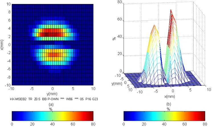
[image:3.595.107.486.468.691.2]Figure 1. Field spatial distribution measured at the plane z = 0.5 mm, with separated excitations of the probe elements: (a) transmitter (T); (b) receiver (R).
Figure 1 shows, by means of a colour scale normalised to the maximum value in each plot, the cross-sectional patterns of the pressure peak values measured at the proximity of the emitting surfaces ( z = 0.5 mm ) for both transducers, transmitter (a) and receiver (b), when they are separately driven by the HV spike generator. It can be appreciated that the T element presents a more intense field radiation level, and that both radiators have a relatively regular amplitude distribution over the aperture plane, though smoothly decaying toward the periphery of the emitting surface.
Figure 2. Spatial distribution of the transient acoustic pressure measured at the plane z = 0.5 mm when both transducers are simultaneously driven: (a) colour scale; (b) 3-D plot.
transducer can be clearly appreciated. Figure 2.b depicts this cross-sectional field distribution but in a 3-D plot, with the pressure amplitudes in the vertical axis. In this plot, the same behaviour of the Figure 2.a, with the pressure amplitudes smoothly increasing toward the probe central zone, can be seen.
It can be appreciated, by comparison with the previous Figure 1, that in spite of the transducer proximity, a very good electrical and acoustical decoupling between both radiators seems to exist. In fact, the behaviour of each element is very similar in the single and double driving cases, as can be verified by comparing the individual performance in figures 1 and 2.
From these measured transversal plots, the unique difference clearly appearing between both emitters, at their respective aperture locations, is related to the vibration amplitude at the central zone in each transducer, which is more intense in the T element.
In order to encounter other type of differences between the field emitted by both elements ( T and R ), longitudinal scannings had to be performed over a central plane perpendicular to the diameter separating both vibrating elements. In this way the direction in which the two ultrasonic beams propagates could be investigated.
Longitudinal Scans Perpendicular to Common Transducers Boundary
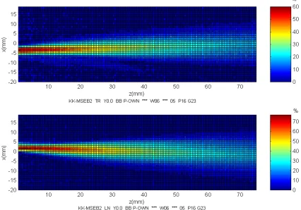
[image:4.595.88.514.433.731.2]With the aim of analysing the beam propagation associated to each element of the dual-transducer NDE probe, longitudinal scannings were performed at the plane perpendicular to the prolongation of the common transducers boundary. In all the longitudinal plots here shown, a field of ±20 x 75 mm was scanned using a step of 0.5 mm in the spatial sampling.
Figure 3 includes two plots in colour scale. They correspond to the longitudinal field distribution radiated by the emitter and receiver transducers (when this last is actuating as an emitter). A quite good evolution results for the beam propagation of both transducer, taking into account that they must diverge in opposite directions of the axis x, in order to produce a certain focusing effect.
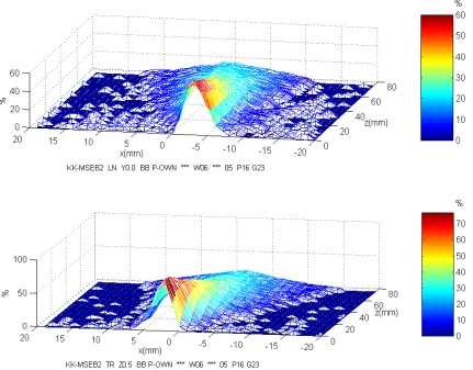
Figure 4. 3-D representation of longitudinal field patterns of Figure 3: above, R; below, T.
The 3-D representations related to the longitudinal field distribution of both transducer are depicted in Figure 4. The propagation of the main part of the ultrasonic beam of the receiver transducer is logically very similar to that observed in Figure 3, but here it can be appreciated more clearly an anomalous extra-lobe in the radiated ultrasonic field, markedly diverging toward a distinct half-plane that the principal lobe.
By analysing the experimental field patterns in figures 3 and 4, its seems that the “nominal receiver” transducer, when is emitting, presents in its field patterns the effects of some non-ideal vibrations/radiations, which are not present in the field patterns measured with the “nominal emitter” transducer. This result in the measured ultrasonic field has been observed, in spite of both transducer seem to have the same size, structure, and constructional process, also having a similar mechanical delay line added in the front of their respective ceramics.
In order to explain this rather anomalous radiation lobe, it could be thought that a different type of electrical matching had been enclosed into each transducer [7]. A study of the input electrical impedance [8] of both transducers as a function of the frequency was made trying to find some differences between the electrical characteristics of the two transducers.
CONCLUSIONS
A dual element transducer, 2 MHz T/R straight beam probe has been investigated using a non-conventional electronic driving and radiating into water. Both the transmitter T and the receiver R transducer elements have been excited separately at different times, and have also been driven simultaneously. The transient peak pressure amplitudes have been measured using a specific experimental set-up, and performing longitudinal and cross-sectional scans.
A good electrical and acoustical decoupling between the T and R transducer elements have been appreciated, with similar emission characteristics near their radiating surface, both in the single and double driving cases, having the R transducer lower vibration amplitude at the central zone than the T transducer. A small anomalous radiation lobe has been appreciated in the near ultrasonic field of the R transducer which could be related to a special parallel electrical tuning.
Acknowledgements: The work described in this paper has been supported by the Spanish R&D Project C.I.C.Y.T. - Ref. TAP99-0864.
REFERENCES
(1) Krautkramer catalogue BL1 ( 8 / 99 ) TD, Handy precision tools for ultrasonic testing, pp.14-15, 39. (1999).
(2) Panametrics catalogue P 399, Ultrasonic Transducers, pp. 6-7, 36. (1999).
(3) J. Krautkramer and H. Krautkramer, Ultrasonic Testing of Materials, Berlin. Edit. Springer-Verlag, (1983).
(4) CICYT Project, TAP99-0864, Nuevos sistemas de exploración pulsada multi-haz para control ultrasónico preciso de características internas en estructuras industriales. R & D National Plan. (5) A. Ramos, J. L. San Emeterio, and P. T. Sanz, Improvement in Transient Piezoelectric Responses of NDE Transceivers Using Selective Damping and Tuning Networks, IEEE Trans. Ultrason., Ferroelect., Freq. Cont, Vol. 47,Nº 4, pp. 826-835. 2000.
(6) J. P. Weight, Miniature ultrasonic probes. Ultrasonic Instrumentation Catalogue. East Sussex, England.
(7) A. Ramos, J.L. San Emeterio, P.T. Sanz, Electrical matching effects on the piezoelectric transduction performance of a through-transmission pulsed process, Ferroelectrics, Vol. 202, pp. 71-80, 1997.
(8) J.L. San Emeterio, A. Ramos, P. T. Sanz, La impedancia eléctrica normalizada de transductores cerámicos piezoeléctricos como herramienta de evaluación y caracterización. Bol. Soc. Esp. Cerámica y Vid., Vol. 38 [ 5 ], pp. 518-521, 1999.
(9) A. Ramos, J.L. San Emeterio y P.T. Sanz, Different tuning contributions in piezoelectric transceivers improving transient signals for ultrasonic imaging, Proceedings XI IEEE