PRUEBA DE HABILIDADES PRÁCTICAS CCNA
DIPLOMADO DE PROFUNDIZACIÓN CISCO (DISEÑO E IMPLEMENTACIÓN DE SOLUCIONES INTEGRADAS LAN / WAN)
OPCION DE GRADO
AUTOR:
HEMIR FIGUEROA COETATA
GRUPO:
203092_27
UNIVERSIDAD NACIONAL ABIERTA Y A DISTANCIA (UNAD)
ESCUELA DE CIENCIAS BASICAS TECNOLOGIA E INGENIERIA (ECBTI)
INGENIERIA DE SISTEMAS
DIPLOMADO CISCO CCNA1 Y CCNA2
PRUEBA DE HABILIDADES PRÁCTICAS CCNA
DIPLOMADO DE PROFUNDIZACIÓN CISCO (DISEÑO E IMPLEMENTACIÓN DE SOLUCIONES INTEGRADAS LAN / WAN)
OPCION DE GRADO
AUTOR:
HEMIR FIGUEROA COETATA
TUTOR:
JUAN CARLOS VESGA
UNIVERSIDAD NACIONAL ABIERTA Y A DISTANCIA (UNAD)
ESCUELA DE CIENCIAS BASICAS TECNOLOGIA E INGENIERIA (ECBTI)
INGENIERIA DE SISTEMAS DIPLOMADO CISCO CCNA1 Y CCNA2
CEAD FLORENCIA CAQUETÁ
TABLA DE CONTENIDO
OBJETIVOS ... 5
ESCENARIO Nro. 1 ... 6
Rutinas de diagnóstico… ... 7
Parte 1: Configuración del enrutamiento... 16
Parte 2: Tabla de Enrutamiento. ... 22
Parte 3: Deshabilitar la propagación del protocolo RIP ... 32
Parte 4: Verificación del protocolo RIP ... 35
Parte 5: Configurar encapsulamiento y autenticación PPP ... 37
Parte 6: Configuración de PAT. ... 41
Parte 7: Configuración del servicio DHCP ... 44
ESCENARIO Nro. 2 ... 48
1. Configurar el direccionamiento IP ... 51
2. Configurar el protocolo de enrutamiento OSPFv2… ... 55
3. Configurar VLANs, Puertos troncales, puertos de acceso, encapsulamiento, Inter- VLAN Routing y Seguridad en los Switches acorde a la topología de red establecida… ... 64
4. En el Switch 3 deshabilitar DNS lookup ... 68
5. Asignar direcciones IP a los Switches acorde a los lineamientos ... 69
6. Desactivar todas las interfaces que no sean utilizadas en el esquema de red… ... 70
7. Implementar DHCP y NAT para IPv4… ... 72
8. Configurar R1 como servidor DHCP para las VLAN 30 y 40 ... 73
9. Reservar las primeras 30 direcciones IP de las VLAN 30 y 40 para configuraciones estáticas ... 74
10. Configurar NAT en R2 para permitir que los host puedan salir a internet… ... 75
11. Configurar al menos dos listas de acceso de tipo estándar a su criterio en para restringir o permitir tráfico desde R1 o R3 hacia R2 ... 76
12. Configurar al menos dos listas de acceso de tipo extendido o nombradas a su criterio en para restringir o permitir tráfico desde R1 o R3 hacia R2… ... 77
13. ..Verificar procesos de comunicación y redireccionamiento de tráfico en los routers mediante el uso de Ping y Traceroute ... 78
INTRODUCCION
Las redes son un común denominador de la tecnología hoy en día. Sin ellas la Internet no existiría y no tendríamos el avance que hoy suponemos que tenemos gracias al surgimiento de la red de redes (INTERNET)
Cisco Packet Tracer de Cisco es un programa de simulación de redes que permite a los estudiantes experimentar con el comportamiento de la red y resolver problemas de redes mucho ante de hacer parte de la solución.
La prueba de habilidades prácticas, corresponde a una solución de un caso de networking dispuesto mediante evaluación que pone a prueba lo aprendido a lo largo del desarrollo del curso y se evidencia en este informe a manera de práctica.
En este Informe se registra la configuración de cada uno de los dispositivos, la descripción detallada del paso a paso de cada una de las etapas realizadas durante su desarrollo, el registro de los procesos de verificación de conectividad mediante el uso de comandos ping, traceroute, show ip route, entre otros.
Para el desarrollo de esta prueba de habilidades se escogió libremente la
herramienta de Simulación Packet Tracer, con la cual se resolverá cada
OBJETIVOS
GENERAL
Dar solución evidenciando el proceso paso a paso al Escenario
consistente en: Una empresa de Tecnología posee tres sucursales
distribuidas en las ciudades de Bogotá, Medellín y Bucaramanga, en donde el estudiante será el administrador de la red, el cual deberá configurar e interconectar entre sí cada uno de los dispositivos que forman parte del escenario, acorde con los lineamientos establecidos para el direccionamiento IP, protocolos de enrutamiento y demás aspectos que forman parte de la topología de red.
ESPECIFICOS
• Crear la topología física y lógica de la red del escenario a desarrollarse.
• Configurar la topología, direccionamiento ip, protocolos de enrutamiento especificada en el escenario objeto de la prueba.
• Simular cada uno de los pasos propuestos en la evaluación evidenciando el paso a paso del desarrollo de la solución.
ESCENARIO Nro. 1
Este escenario plantea el uso de RIP como protocolo de enrutamiento, considerando que se tendran rutas por defecto redistribuidas; asimismo, habilitar el encapsulamiento PPP y su autenticación.
Los routers Bogota2 y medellin2 proporcionan el servicio DHCP a su propia red LAN y a los routers 3 de cada ciudad.
DESARROLLO:
Como trabajo inicial se debe realizar lo siguiente.
Rutinas de diagnóstico y dejar los equipos listos para su configuración (asignar nombres de equipos, asignar claves de seguridad, etc).
CONFIGURACION DE ROUTER ISP (R-ISP)
en conf t
conf terminal hostname R-ISP no ip domain-lookup enable secret cisco line con 0
password cisco login
line vty 0 4 password cisco login
exit
service password-encryption
banner motd $*****ACCESO PROHIBIDO - SOLO PERSONAL AUTORIZADO*****$
int s0/0/0
ip add 209.17.220.1 255.255.255.252 clock rate 4000000
no shut
int s0/0/1
ip add 209.17.220.5 255.255.255.252 clock rate 4000000
CONFIGURACION DE ROUTER MEDELLIN1
Router(config)#hostname MEDELLIN1 MEDELLIN1(config)#no ip domain-lookup MEDELLIN1(config)#enable secret cisco MEDELLIN1(config)#line con 0
MEDELLIN1(config)#password cisco MEDELLIN1(config)#login
MEDELLIN1(config)#line vty 0 4 MEDELLIN1(config)#password cisco MEDELLIN1(config)#login
exit
MEDELLIN1(config)#service password-encryption
banner motd $*****ACCESO PROHIBIDO - SOLO PERSONAL AUTORIZADO*****$
*****AHORA CONFIGURAR LAS INTERFACES*****
MEDELLIN1(config)#
MEDELLIN1(config)#int s0/0/0
MEDELLIN1(config-if)#ip add 209.17.220.2 255.255.255.252 MEDELLIN1(config-if)#no shut
MEDELLIN1(config)#int s0/0/1
MEDELLIN1(config-if)#ip add 172.29.6.1 255.255.255.252 MEDELLIN1(config-if)#clock rate 4000000
MEDELLIN1(config-if)#no shut
MEDELLIN1(config-if)#int s0/1/0
MEDELLIN1(config-if)#ip add 172.29.6.9 255.255.255.252 MEDELLIN1(config-if)#clock rate 4000000
MEDELLIN1(config-if)#no shut
MEDELLIN1(config-if)#int s0/1/1
MEDELLIN1(config-if)#ip add 172.29.6.13 255.255.255.252 MEDELLIN1(config-if)#clock rate 4000000
CONFIGURACION DE ROUTER MEDELLIN2
hostname MEDELLIN2 no ip domain-lookup enable secret cisco line con 0
password cisco login
line vty 0 4 password cisco login
exit
service password-encryption
banner motd $*****ACCESO PROHIBIDO - SOLO PERSONAL AUTORIZADO*****$
int s0/0/0
ip add 172.29.6.2 255.255.255.252 no shut
int s0/0/1
ip add 172.29.6.5 255.255.255.252 clock rate 4000000
no shut
int g0/0
CONFIGURACION DE ROUTER MEDELLIN3
hostname MEDELLIN3 no ip domain-lookup enable secret cisco line con 0
password cisco login
line vty 0 4 password cisco login
exit
service password-encryption
banner motd $*****ACCESO PROHIBIDO - SOLO PERSONAL AUTORIZADO*****$
*****AHORA CONFIGURAR LAS INTERFACES*****
MEDELLIN2(config-if)#int s0/0/0
MEDELLIN2(config-if)#ip add 172.29.6.10 255.255.255.252 MEDELLIN2(config-if)#no shut
MEDELLIN2(config-if)#int s0/0/1
MEDELLIN2(config-if)#ip add 172.29.6.14 255.255.255.252 MEDELLIN2(config-if)#no shut
MEDELLIN2(config-if)#int s0/1/0
MEDELLIN2(config-if)#ip add 172.29.6.6 255.255.255.252 MEDELLIN2(config-if)#no shut
MEDELLIN2(config-if)#int g0/0
CONFIGURACION DE ROUTER BOGOTA1
Router#conf t
Enter configuration commands, one per line. End with CNTL/Z. Router(config)#host BOGOTA1
BOGOTA1(config)#enable secret cisco BOGOTA1(config)#line con 0
BOGOTA1(config-line)#pass cisco BOGOTA1(config-line)#login BOGOTA1(config-line)#line vty 0 4 BOGOTA1(config-line)#pass cisco BOGOTA1(config-line)#login BOGOTA1(config-line)#exit
BOGOTA1(config)#service password-encryption
BOGOTA1(config)#banner motd $*****ACCESO PROHIBIDO - SOLO PERSONAL AUTORIZADO*****$
*****AHORA CONFIGURAR LAS INTERFACES*****
BOGOTA1(config)#int s0/0/0
BOGOTA1(config-if)#ip add 209.17.220.6 255.255.255.252 BOGOTA1(config-if)#no shut
%LINK-5-CHANGED: Interface Serial0/0/0, changed state to up
BOGOTA1(config-if)#int s0/0/1
%LINEPROTO-5-UPDOWN: Line protocol on Interface Serial0/0/0, changed state to up BOGOTA1(config-if)#ip add 172.29.3.9 255.255.255.252
BOGOTA1(config-if)#clock rate 4000000 BOGOTA1(config-if)#no shut
%LINK-5-CHANGED: Interface Serial0/0/1, changed state to down
BOGOTA1(config-if)#int s0/1/0
BOGOTA1(config-if)#ip add 172.29.3.1 255.255.255.252 BOGOTA1(config-if)#clock rate 4000000
BOGOTA1(config-if)#no shut
BOGOTA1(config-if)#int s0/1/1
BOGOTA1(config-if)#ip add 172.29.3.5 255.255.255.252 BOGOTA1(config-if)#clock rate 4000000
CONFIGURACION DE ROUTER BOGOTA2
Router#conf t
Enter configuration commands, one per line. End with CNTL/Z. Router(config)#host
Router(config)#hostname BOGOTA2 BOGOTA2(config)#enable secret cisco BOGOTA2(config)#line con 0
BOGOTA2(config-line)#pass cisco BOGOTA2(config-line)#login BOGOTA2(config-line)#line vty 0 4 BOGOTA2(config-line)#pass cisco BOGOTA2(config-line)#login BOGOTA2(config-line)#exit
BOGOTA2(config)#service password-encryption
BOGOTA2(config)#banner motd $*****ACCESO PROHIBIDO - SOLO PERSONAL AUTORIZADO*****$
*****AHORA CONFIGURAR LAS INTERFACES*****
BOGOTA2(config)#int s0/0/0
BOGOTA2(config-if)#ip add 172.29.3.10 255.255.255.252 BOGOTA2(config-if)#no shut
BOGOTA2(config-if)#
%LINK-5-CHANGED: Interface Serial0/0/0, changed state to up
BOGOTA2(config-if)#int s0/0/1
BOGOTA2(config-if)#ip add 172.29.3.13 255.255.255.252 BOGOTA2(config-if)#clock rate 4000000
BOGOTA2(config-if)#no shut
%LINK-5-CHANGED: Interface Serial0/0/1, changed state to down
BOGOTA2(config-if)#int g0/0
BOGOTA2(config-if)#ip add 172.29.1.1 255.255.255.0 BOGOTA2(config-if)#no shut
%LINK-5-CHANGED: Interface GigabitEthernet0/0, changed state to up
CONFIGURACION DE ROUTER BOGOTA3
Router#conf t
Enter configuration commands, one per line. End with CNTL/Z. Router(config)#hostname BOGOTA3
BOGOTA3(config)#LINE BOGOTA3(config)#line con 0 BOGOTA3(config-line)#pass cisco BOGOTA3(config-line)#login BOGOTA3(config-line)#line vty 0 4 BOGOTA3(config-line)#pass cisco BOGOTA3(config-line)#login
BOGOTA3(config-line)#enable secret class BOGOTA3(config)#enable secret class
BOGOTA3(config)#service password-encryption
BOGOTA3(config)#banner motd $*****ACCESO PROHIBIDO - SOLO PERSONAL AUTORIZADO*****$
*****AHORA CONFIGURAR LAS INTERFACES*****
BOGOTA3(config)#INT S0/0/0
BOGOTA3(config-if)#ip add 172.29.3.2 255.255.255.252 BOGOTA3(config-if)#no shut
BOGOTA3(config-if)#INT S0/0/1
BOGOTA3(config-if)#ip add 172.29.3.6 255.255.255.252 BOGOTA3(config-if)#no shut
BOGOTA3(config)#int s0/1/0
BOGOTA3(config-if)#ip add 172.29.3.14 255.255.255.252 BOGOTA3(config-if)#no shut
BOGOTA3(config-if)#int g0/0
BOGOTA3(config-if)#ip add 172.29.0.1 255.255.255.128 BOGOTA3(config-if)#no shut
%LINK-5-CHANGED: Interface GigabitEthernet0/0, changed state to up
%LINEPROTO-5-UPDOWN: Line protocol on Interface GigabitEthernet0/0, changed state to up
BOGOTA3(config-if)#int s0/1/0
BOGOTA3(config-if)#no shut
• Realizar la conexión fisica de los equipos con base en la topología de red
• Configurar la topología de red, de acuerdo con las siguientes especificaciones.
La figura 1 permite observar la implementación de la topología de red propuesta con sus interfaces activas
Parte 1: Configuración del enrutamiento
a. Configurar el enrutamiento en la red usando el protocolo RIP versión 2, declare la red principal, desactive la sumarización automática.
MEDELLIN1 MEDELLIN1>en MEDELLIN1#conf t MEDELLIN1(config)#router rip MEDELLIN1(config-router)#version 2 MEDELLIN1(config-router)#no auto-summary
MEDELLIN1(config-router)#do show ip route connected
C 172.29.6.0/30 is directly connected, Serial0/0/1 C 172.29.6.8/30 is directly connected, Serial0/1/0 C 172.29.6.12/30 is directly connected, Serial0/1/1 C 209.17.220.0/30 is directly connected, Serial0/0/0
MEDELLIN1(config-router)#network 172.29.6.0 MEDELLIN1(config-router)#network 172.29.6.8 MEDELLIN1(config-router)#network 172.29.6.12 MEDELLIN1(config-router)#passive-interface s0/0/0 MEDELLIN2 MEDELLIN2>en MEDELLIN2#conf t MEDELLIN2(config)#router rip MEDELLIN2(config-router)#version 2 MEDELLIN2(config-router)#no auto-summary
MEDELLIN2(config-router)#do show ip route connected C 172.29.4.0/25 is directly connected, GigabitEthernet0/0 C 172.29.6.0/30 is directly connected, Serial0/0/0
MEDELLIN3 MEDELLIN3>en MEDELLIN3#conf t MEDELLIN3(config)#router rip MEDELLIN3(config-router)#version 2 MEDELLIN3(config-router)#no auto-summary
MEDELLIN3(config-router)#do show ip route connected C 172.29.4.128/25 is directly connected, GigabitEthernet0/0 C 172.29.6.4/30 is directly connected, Serial0/1/0
C 172.29.6.8/30 is directly connected, Serial0/0/0 C 172.29.6.12/30 is directly connected, Serial0/0/1 MEDELLIN3(config-router)#network 172.29.4.128 MEDELLIN3(config-router)#network 172.29.6.4 MEDELLIN3(config-router)#network 172.29.6.8 MEDELLIN3(config-router)#network 172.29.6.12 MEDELLIN3(config-router)#passive-interface g0/0 BOGOTA1 Bogota1>en Bogota1#conf t Bogota1(config)#router rip Bogota1(config-router)#version 2 Bogota1(config-router)#no auto-summary
Bogota1(config-router)#do show ip route connected C 172.29.3.0/30 is directly connected, Serial0/1/0 C 172.29.3.4/30 is directly connected, Serial0/1/1 C 172.29.3.8/30 is directly connected, Serial0/0/1 C 209.17.220.4/30 is directly connected, Serial0/0/0 Bogota1(config-router)#network 172.29.3.0
BOGOTA2 BOGOTA2>en BOGOTA2#conf t BOGOTA2(config)#router rip BOGOTA2(config-router)#version 2 BOGOTA2(config-router)#no auto-summary
BOGOTA2(config-router)#do show ip route connected C 172.29.1.0/24 is directly connected, GigabitEthernet0/0 C 172.29.3.8/30 is directly connected, Serial0/0/0
C 172.29.3.12/30 is directly connected, Serial0/0/1 BOGOTA2(config-router)#network 172.29.1.0 BOGOTA2(config-router)#network 172.29.3.8 BOGOTA2(config-router)#network 172.29.3.12 BOGOTA2(config-router)#passive-interface g0/0 BOGOTA3 BOGOTA3(config)#router rip BOGOTA3(config-router)#version 2 BOGOTA3(config-router)#no auto-summary
BOGOTA3(config-router)#do show ip route connected C 172.29.0.0/25 is directly connected, GigabitEthernet0/0 C 172.29.3.0/30 is directly connected, Serial0/0/0
C 172.29.3.4/30 is directly connected, Serial0/0/1 C 172.29.3.12/30 is directly connected, Serial0/1/0 BOGOTA3(config-router)#network 172.29.0.0
La figura 2 permite observar el protocolo RIP mostrando las redes publicadas
b. Los routers Bogota1 y Medellín deberán añadir a su configuración de enrutamiento una ruta por defecto hacia el ISP y, a su vez, redistribuirla dentro de las publicaciones de RIP.
MEDELLIN1
MEDELLIN1(config)#ip route 0.0.0.0 0.0.0.0 209.17.220.1 MEDELLIN1(config)#route rip
MEDELLIN1(config-router)#default-information originate
BOGOTA1
BOGOTA1(config)#ip route 0.0.0.0 0.0.0.0 209.17.220.5 BOGOTA1(config)#router rip
c. El router ISP deberá tener una ruta estática dirigida hacia cada red interna de Bogotá y Medellín para el caso se sumarizan las subredes de cada uno a /22.
Parte 2: Tabla de Enrutamiento.
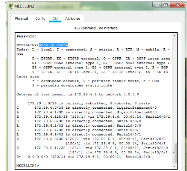
a. Verificar la tabla de enrutamiento en cada uno de los routers para comprobar las redes y sus rutas.
Al ingresar el comando show run o show ip route en cada router puede obtenerse la
informacion de enrutamiento.
En este caso vamos a utilizar el siguiente comando:
show ip route
b. Verificar el balanceo de carga que presentan los routers.
c. Obsérvese en los routers Bogotá1 y Medellín1 cierta similitud por su ubicación, por tener dos enlaces de conexión hacia otro router y por la ruta por defecto que manejan.
d. Los routers Medellín2 y Bogotá2 también presentan redes conectadas directamente y recibidas mediante RIP.
e. Las tablas de los routers restantes deben permitir visualizar rutas redundantes para el caso de la ruta por defecto.
f. El router ISP solo debe indicar sus rutas estáticas adicionales a las directamente conectadas.
Parte 3: Deshabilitar la propagación del protocolo RIP.
a. Para no propagar las publicaciones por interfaces que no lo requieran se debe deshabilitar la propagación del protocolo RIP, en la siguiente tabla se indican las interfaces de cada router que no necesitan desactivación.
Para este ejercicio, se debe deshabilitar el envío de información de enrutamiento por los interfaces de los router Medellín 2 Medellín 3, Bogotá 2 y Bogotá 3, lo cuales se dirigen hacia los hosts.
BOGOTA1
BOGOTA1#conf t
Enter configuration commands, one per line. End with CNTL/Z. BOGOTA1(config)#router rip
BOGOTA1(config-router)#version 2
OGOTA1(config-router)#passive-interface g0/0 BOGOTA1(config-router)#passive-interface g0/1 BOGOTA1(config-router)# DO WR
BOGOTA2
BOGOTA2#conf t
Enter configuration commands, one per line. End with CNTL/Z. BOGOTA2(config)#router rip BOGOTA2(config-router)#version 2 BOGOTA2(config-router)#passive-interface g0/0 BOGOTA2(config-router)#passive-interface g0/1 BOGOTA2(config-router)#DO WR Building configuration... [OK] BOGOTA3 BOGOTA3#conf t
Enter configuration commands, one per line. End with CNTL/Z. BOGOTA3(config)#router rip BOGOTA3(config-router)#version 2 BOGOTA3(config-router)#passive-interface s0/1/1 BOGOTA3(config-router)#passive-interface g0/0 BOGOTA3(config-router)#passive-interface g0/1 BOGOTA3(config-router)#do wr Building configuration... [OK] MEDELLIN1 MEDELLIN1#conf t
MEDELLIN2(config-router)#version 2
MEDELLIN2(config-router)#passive-interface g0/0 MEDELLIN2(config-router)#passive-interface g0/1 MEDELLIN2(config-router)#do wr
Building configuration... [OK]
MEDELLIN3
MEDELLIN3#conf t
Enter configuration commands, one per line. End with CNTL/Z. MEDELLIN3(config)#router rip
MEDELLIN3(config-router)#version 2
MEDELLIN3(config-router)#passive-interface s0/1/1 MEDELLIN3(config-router)#passive-interface g0/0 MEDELLIN3(config-router)#passive-interface g0/1 MEDELLIN3(config-router)#do wr
Se realiza la verificación de los protocolos a través del comando: show ip route Parte 4: Verificación del protocolo RIP.
a. Verificar y documentar las opciones de enrutamiento configuradas en los routers, como el passive interface para la conexión hacia el ISP, la versión de RIP y las interfaces que participan de la publicación entre otros datos.
b. Verificar y documentar la base de datos de RIP de cada router, donde se informa de manera detallada de todas las rutas hacia cada red.
ROUTER
RUTAS RIP
MEDELLIN1 R 172.29.4.128/25 [120/1] via 172.29.6.10, 00:00:19,
MEDELLIN2
R 172.29.6.12/30 [120/1] via 172.29.6.6, 00:00:18, Serial0/0/1 [120/1] via 172.29.6.1, 00:00:01, Serial0/0/0
R* 0.0.0.0/0 [120/1] via 172.29.6.1, 00:00:01, Serial0/0/0
MEDELLIN3
R* 0.0.0.0/0 [120/1] via 172.29.6.9, 00:00:17, Serial0/0/0 [120/1] via 172.29.6.13, 00:00:17, Serial0/0/1
BOGOTA1
R 172.29.0.0/25 [120/1] via 172.29.3.6, 00:00:08, Serial0/1/1 [120/1] via 172.29.3.2, 00:00:08, Serial0/1/0
R 172.29.1.0/24 [120/1] via 172.29.3.10, 00:00:19, Serial0/0/1 BOGOTA2 R 172.29.0.0/25 [120/1] via 172.29.3.14, 00:00:12, Serial0/0/1 R 172.29.3.0/30 [120/1] via 172.29.3.9, 00:00:09, Serial0/0/0 [120/1] via 172.29.3.14, 00:00:12, Serial0/0/1
R 172.29.3.4/30 [120/1] via 172.29.3.9, 00:00:09, Serial0/0/0 [120/1] via 172.29.3.14, 00:00:12, Serial0/0/1
R* 0.0.0.0/0 [120/1] via 172.29.3.9, 00:00:09, Serial0/0/0
BOGOTA3 R 172.29.3.8/30 [120/1] via 172.29.3.5, 00:00:24, Serial0/0/1 [120/1] via 172.29.3.1, 00:00:24, Serial0/0/0
[120/1] via 172.29.3.13, 00:00:01, Serial0/1/0
R* 0.0.0.0/0 [120/1] via 172.29.3.5, 00:00:24, Serial0/0/1 [120/1] via 172.29.3.1, 00:00:24, Serial0/0/0
Parte 5: Configurar encapsulamiento y autenticación PPP.
a. Según la topología se requiere que el enlace Medellín1 con ISP sea configurado con autenticación PAP.
En el ISP
R-ISP(config)#username MEDELLIN1 PASSWORD 1234 R-ISP(config)#INT S0/0/0
R-ISP(config-if)#encapsulation ppp R-ISP(config-if)#ppp authentication pap R-ISP(config-if)#
%LINEPROTO-5-UPDOWN: Line protocol on Interface Serial0/0/0, changed state to up
R-ISP(config-if)#ppp pap sent-username R-ISP password 1234 R-ISP(config-if)#do wr
Building configuration... [OK]
En el router MEDELLIN1
MEDELLIN(config)#username R-ISP password 1234 MEDELLIN(config)#
%LINEPROTO-5-UPDOWN: Line protocol on Interface Serial0/0/0, changed state to up
MEDELLIN(config)#int s0/0/0
MEDELLIN(config-if)#encapsulation ppp MEDELLIN(config-if)#ppp authentication pap
MEDELLIN(config-if)#ppp pap sent-username MEDELLIN1 password 1234 MEDELLIN(config-if)#DO WR
La figura 18 muestra los resultados de hacer ping entre el ISP y MEDELLIN1
b. El enlace Bogotá1 con ISP se debe configurar con autenticación CHAP.
En el ISP
R-ISP(config)#username BOGOTA1 password 1234 R-ISP(config)#int s0/0/1
R-ISP(config-if)#encapsulation ppp R-ISP(config-if)#ppp authentication chap R-ISP(config-if)#
R-ISP(config-if)# R-ISP(config-if)#end R-ISP#
%SYS-5-CONFIG_I: Configured from console by console
R-ISP#
%LINEPROTO-5-UPDOWN: Line protocol on Interface Serial0/0/1, changed state to up
En el BOGOTA1
BOGOTA1(config)#username R-ISP password 1234 BOGOTA1(config)#int s0/0/0
BOGOTA1(config-if)#encapsulation ppp BOGOTA1(config-if)#ppp authentication chap BOGOTA1(config-if)#end
BOGOTA1#
La figura 19 muestra los resultados de hacer ping entre el ISP y BOGOTA1
Parte 6: Configuración de PAT.
a. En la topología, si se activa NAT en cada equipo de salida (Bogotá1 y Medellín1), los routers internos de una ciudad no podrán llegar hasta los routers internos en el otro extremo, sólo existirá comunicación hasta los routers Bogotá1, ISP y Medellín1.
MEDELLIN1
MEDELLIN1(config)#ip nat inside source list interface s0/0/0 overload MEDELLIN1(config)#access-list 1 permit 172.29.4.0 0.0.3.255
MEDELLIN1(config-if)#int s0/0/0 MEDELLIN1(config-if)#ip nat outside MEDELLIN1(config-if)#int s0/0/1 MEDELLIN1(config-if)#ip nat inside MEDELLIN1(config-if)#int s0/1/0 MEDELLIN1(config-if)#ip nat inside MEDELLIN1(config-if)#int s0/1/1 MEDELLIN1(config-if)#ip nat inside MEDELLIN1(config-if)# MEDELLIN1(config-if)#do wr Building configuration... [OK] MEDELLIN1(config-if)# MEDELLIN1(config-if)# BOGOTA1
BOGOTA1(config)#access-list 1 permit 172.29.0.0 0.0.3.255 BOGOTA1(config)#int s0/0/0
BOGOTA1(config-if)#ip nat outside BOGOTA1(config-if)#int s0/0/1 BOGOTA1(config-if)#ip nat inside BOGOTA1(config-if)#int s0/1/0 BOGOTA1(config-if)#ip nat inside BOGOTA1(config-if)#int s0/1/1 BOGOTA1(config-if)#ip nat inside BOGOTA1(config-if)#
Figura muestra los ping desde los equipos a el ISP
b. Después de verificar lo indicado en el paso anterior proceda a configurar el NAT en el router Medellín1. Compruebe que la traducción de direcciones indique las interfaces de entrada y de salida. Al realizar una prueba de ping, la dirección debe ser traducida automáticamente a la dirección de la interfaz serial 0/1/0 del router Medellín1, cómo diferente puerto.
Figura 21
c. Proceda a configurar el NAT en el router BOGOTA1. Compruebe que la traducción de direcciones indique las interfaces de entrada y de salida. Al realizar una prueba de ping, la dirección debe ser traducida automáticamente a la dirección de la interfaz serial 0/1/0 del router Bogotá1, cómo diferente puerto.
Parte 7: Configuración del servicio DHCP.
a. Configurar la red Medellín2 y Medellín3 donde el router Medellín 2 debe ser el servidor DHCP para ambas redes Lan.
b. El router Medellín3 deberá habilitar el paso de los mensajes broadcast hacia la IP del router Medellín2.
En el router MEDELLIN2
MEDELLIN2#conf t
Enter configuration commands, one per line. End with CNTL/Z.
MEDELLIN2(config)#ip dhcp excluded-address 172.29.4.1 172.29.4.5 MEDELLIN2(config)#ip dhcp excluded-address 172.29.4.129 172.29.4.133 MEDELLIN2(config)#ip dhcp pool PRIMERA
MEDELLIN2(dhcp-config)#NEtwork 172.29.4.0 255.255.255.128 MEDELLIN2(dhcp-config)#DEfault-router 172.29.4.1
MEDELLIN2(dhcp-config)#dns-server 8.8.8.8 MEDELLIN2(dhcp-config)#exit
MEDELLIN2(config)#ip dhcp pool SEGUNDA
MEDELLIN2(dhcp-config)#NEtwork 172.29.4.128 255.255.255.128 MEDELLIN2(dhcp-config)#DEfault-router 172.29.4.129 MEDELLIN2(dhcp-config)#dns-server 8.8.8.8 MEDELLIN2(dhcp-config)#exit MEDELLIN2(config)#do wr Building configuration... [OK]
En el router MEDELLIN3
MEDELLIN3#conf t
Enter configuration commands, one per line. End with CNTL/Z. MEDELLIN3(config)#int g0/0
MEDELLIN3(config-if)#ip helper-address 172.29.6.5 MEDELLIN3(config-if)#do wr
Figura muestra el direccionamiento IP mediante DHCP al router MEDELLIN2 desde su propia red y desde la red de MEDELLIN3
c. Configurar la red Bogotá2 y Bogotá3 donde el router Medellín2 debe ser el servidor DHCP para ambas redes Lan.
d. Configure el router Bogotá1 para que habilite el paso de los mensajes Broadcast hacia la IP del router Bogotá2.
En el router BOGOTA2 se realiza la siguiente configuración
BOGOTA2#conf t
Enter configuration commands, one per line. End with CNTL/Z. BOGOTA2(config)#ip dhcp excluded-address 172.29.1.1 172.29.1.5 BOGOTA2(config)#ip dhcp excluded-address 172.29.0.1 172.29.0.5 BOGOTA2(config)#ip dhcp pool TERCERA
BOGOTA2(dhcp-config)#network 172.29.1.0 255.255.255.0 BOGOTA2(dhcp-config)#default-router 172.29.1.1
BOGOTA2(dhcp-config)#dns-server 0.0.0.0 BOGOTA2(dhcp-config)#ip dhcp pool CUARTA
BOGOTA2(dhcp-config)#network 172.29.0.0 255.255.255.0 BOGOTA2(dhcp-config)#default-router 172.29.0.1
BOGOTA2(dhcp-config)#dns-server 0.0.0.0 BOGOTA2(dhcp-config)#do wr
Figura muestra el direccionamiento IP mediante DHCP al router BOGOTA2 desde su propia red y desde la red de BOGOTA3
ESCENARIO Nro. 2
Escenario: Una empresa de Tecnología posee tres sucursales distribuidas en las
ciudades de Bogotá, Medellín y Bucaramanga, en donde el estudiante será el administrador de la red, el cual deberá configurar e interconectar entre sí cada uno de los dispositivos que forman parte del escenario, acorde con los lineamientos establecidos para el direccionamiento IP, protocolos de enrutamiento y demás aspectos que forman parte de la topología de red.
Topología de red
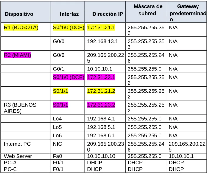
Configurar el direccionamiento IP acorde con la topología de red para cada uno de los dispositivos que forman parte del escenario.
Tabla de direccionamiento
Dispositivo Interfaz Dirección IP
Máscara de Gateway
subred predeterminad
o
R1 (BOGOTÁ) S0/1/0 (DCE) 172.31.21.1 255.255.255.25
2
N/A
G0/0 192.168.13.1 255.255.255.25
2
N/A
R2 (MIAMI) G0/0 209.165.200.22
5
255.255.255.24 8
N/A
G0/1 10.10.10.1 255.255.255.0 N/A
S0/1/0 (DCE) 172.31.23.1 255.255.255.25
2
N/A
S0/1/1 172.31.21.2 255.255.255.25
2
N/A
R3 (BUENOS AIRES)
S0/1/1 172.31.23.2 255.255.255.25
2
N/A
Lo4 192.168.4.1 255.255.255.0 N/A
Lo5 192.168.5.1 255.255.255.0 N/A
Lo6 192.168.6.1 255.255.255.0 N/A
Internet PC NIC 209.165.200.23
0
255.255.255.24 8
209.165.200.22 5
Web Server Fa0 10.10.10.10 255.255.255.0 10.10.10.1
PC-A F0/1 DHCP DHCP DHCP
TOPOLOGIA
1. Configurar el direccionamiento IP acorde con la topología de red para cada uno de los dispositivos que forman parte del escenario
Direccionamiento ip (Internet PC)
R1 (BOGOTA)
Router#conf t
Enter configuration commands, one per line. End with CNTL/Z. Router(config)#hostname BOGOTA
BOGOTA(config)#inter
BOGOTA(config)#interface s0/0/0 BOGOTA(config-if)#ip add
BOGOTA(config-if)#ip address 172.31.21.1 255.255.255.252 BOGOTA(config-if)#clock rate 64000
BOGOTA(config-if)#no sh
BOGOTA(config-if)#no shutdown
%LINK-5-CHANGED: Interface Serial0/0/0, changed state to down BOGOTA(config-if)#
BOGOTA#
%SYS-5-CONFIG_I: Configured from console by console
R2 (MIAMI)
MIAMI>en MIAMI#conf t
Enter configuration commands, one per line. End with CNTL/Z. MIAMI(config)#int loop0
MIAMI(config-if)#ip address 10.10.10.10 255.255.255.255 MIAMI(config-if)#no shutdown
MIAMI(config-if)#int s0/0/0
MIAMI(config-if)#ip address 172.31.23.1 255.255.255.252 MIAMI(config-if)#clock rate 64000
MIAMI(config-if)#no shutdown
%LINK-5-CHANGED: Interface Serial0/0/0, changed state to down MIAMI(config-if)#exit
MIAMI(config)#int s0/0/1
MIAMI(config-if)#ip address 172.31.21.2 255.255.255.252 MIAMI(config-if)#no shutdown
MIAMI(config-if)#
%LINK-5-CHANGED: Interface Serial0/0/1, changed state to up
%LINEPROTO-5-UPDOWN: Line protocol on Interface Serial0/0/1, changed state to up MIAMI(config-if)#exit
MIAMI(config)#int g0/0
se procede a configurar las interfaces para el servidor web y el proveedor de servicio de internet en el router 2
MIAMI(config)#int g0/1
MIAMI(config-if)#ip add 10.10.10.1 255.255.255.0 MIAMI(config-if)#no shutdown
Se prueba realizando ping entre R1 y R2
R3 (BUENOS AIRES)
enable config t
hostname BUENOS_AIRES int loop4 ip add 192.168.4.1 255.255.255.0 no shut int loop5
ip add 192.168.5.1 255.255.255.0 no shut int loop4
ip add 192.168.6.1 255.255.255.0 no shut int s0/0/1
2. Configurar el protocolo de enrutamiento OSPFv2 bajo los siguientes criterios:
OSPFv2 area 0
Configuration Item or Task Specification
Router ID R1 1.1.1.1
Router ID R2 5.5.5.5
Router ID R3 8.8.8.8
Configurar todas las interfaces LAN como pasivas
Establecer el ancho de banda para enlaces seriales en 256 Kb/s
Ajustar el costo en la métrica de S0/0 a 9500
CONFIGURACIÓN OSPF V2
R1 (BOGOTA)
enable
config t router ospf 1 router-id 1.1.1.1
network 192.168.99.0 0.0.0.255 area 0 network 172.31.21.0 0.0.0.3 area 0 passive-interface gi0/0 int s0/1/0
bandwidth 256 ip ospf cost 9500 int s0/1/1 bandwidth 256 passive-interface f0/0
R2 (MIAMI)
enable
config t router ospf 1 router-id 5.5.5.5
network 209.165.200.224 0.0.0.7 area 0 network 172.31.21.0 0.0.0.3 area 0
network 10.10.10.10 0.0.0.3 area 0 passive-interface gi0/0
R3 (BUENOS AIRES)
config t router ospf 1 router-id 8.8.8.8
network 172.31.23.0 0.0.0.3 area 0 network 192.168.4.0 0.0.0.255 area 0 network 192.168.5.0 0.0.0.255 area 0
network 192.168.6.0 0.0.0.255 area 0 int s0/1/1
Configuración WEB Server
Verificar información de OSPF
enable
show ip ospf neighbor
Figura 30
Visualizar lista resumida de interfaces por OSPF en donde se ilustre el costo de cada interface
show ip ospf interface
Visualisar el OSPF Process ID, Router ID, Address summarizations, Routing Networks, and passive interfaces configuradas en cada router.
3. Configurar VLANs, Puertos troncales, puertos de acceso, encapsulamiento, Inter- VLAN Routing y Seguridad en los Switches acorde a la topología de red establecida.
Configuración del switch 1
Switch>enable
Switch#erase startup-config
Erasing the nvram filesystem will remove all configuration files! Continue? [confirm] [OK]
Erase of nvram: complete
%SYS-7-NV_BLOCK_INIT: Initialized the geometry of nvram Switch#
Switch#conf t
Enter configuration commands, one per line. End with CNTL/Z. Switch(config)#host S1
S1(config)#enable secret class S1(config)#line con 0
S1(config-line)#pass cisco S1(config-line)#login S1(config-line)#line vty 0 4 S1(config-line)#pass cisco S1(config-line)#exit
S1(config)#service password-encryption
S1(config)#banner motd 'ACCESO RESTRINGIDO A PERSONAL NO AUTORIZADO' %SYS-5-CONFIG_I: Configured from console by console
S1(config)#vlan 30 S1(config-vlan)#name ADMINISTRACION S1(config-vlan)#vlan 40 S1(config-vlan)#name MERCADEO S1(config-vlan)#vlan 200 S1(config-vlan)#name MANTENIMIENTO S1(config-vlan)#int vlan 200
S1(config-if)#
%LINK-5-CHANGED: Interface Vlan200, changed state to up S1(config-if)#ip add
S1(config-if)#ip address 192.168.200.2 255.255.255.0 S1(config-if)#ip default-gateway 192.168.200.1
S1(config)#int f0/3
S1(config-if)#
%LINEPROTO-5-UPDOWN: Line protocol on Interface FastEthernet0/3, changed state to down
%LINEPROTO-5-UPDOWN: Line protocol on Interface FastEthernet0/3, changed state to up
%LINEPROTO-5-UPDOWN: Line protocol on Interface Vlan200, changed state to up S1(config-if)#switchport trunk native vlan 1
S1(config-if)#int f0/24
S1(config-if)#switchport mode trunk
S1(config-if)#switchport trunk native vlan 1 S1(config-if)#int range f0/2, f0/4-23, g0/1-2 S1(config-if-range)#switchport mode access S1(config-if-range)#int f0/1
S1(config-if)#switchport access vlan 30 S1(config-if)#int range f0/2, f0/4-23, g0/1-2 S1(config-if-range)#shut
S1(config-if-range)#shutdown
%LINK-5-CHANGED: Interface FastEthernet0/2, changed state to administratively down %LINK-5-CHANGED: Interface FastEthernet0/4, changed state to administratively down %LINK-5-CHANGED: Interface FastEthernet0/5, changed state to administratively down %LINK-5-CHANGED: Interface FastEthernet0/6, changed state to administratively down %LINK-5-CHANGED: Interface FastEthernet0/7, changed state to administratively down %LINK-5-CHANGED: Interface FastEthernet0/8, changed state to administratively down %LINK-5-CHANGED: Interface FastEthernet0/9, changed state to administratively down %LINK-5-CHANGED: Interface FastEthernet0/10, changed state to administratively down %LINK-5-CHANGED: Interface FastEthernet0/11, changed state to administratively down %LINK-5-CHANGED: Interface FastEthernet0/12, changed state to administratively down %LINK-5-CHANGED: Interface FastEthernet0/13, changed state to administratively down %LINK-5-CHANGED: Interface FastEthernet0/14, changed state to administratively down %LINK-5-CHANGED: Interface FastEthernet0/15, changed state to administratively down %LINK-5-CHANGED: Interface FastEthernet0/16, changed state to administratively down %LINK-5-CHANGED: Interface FastEthernet0/17, changed state to administratively down %LINK-5-CHANGED: Interface FastEthernet0/18, changed state to administratively down %LINK-5-CHANGED: Interface FastEthernet0/19, changed state to administratively down %LINK-5-CHANGED: Interface FastEthernet0/20, changed state to administratively down %LINK-5-CHANGED: Interface FastEthernet0/21, changed state to administratively down %LINK-5-CHANGED: Interface FastEthernet0/22, changed state to administratively down %LINK-5-CHANGED: Interface FastEthernet0/23, changed state to administratively down %LINK-5-CHANGED: Interface GigabitEthernet0/1, changed state to administratively down
Configuración del switch 3
Switch#conf t
Enter configuration commands, one per line. End with CNTL/Z. Switch(config)#host S3
S3(config)#enable secret class S3(config)#line con 0
S3(config-line)#pass cisco S3(config-line)#login S3(config-line)#line vty 0 4 S3(config-line)#pass cisco S3(config-line)#login S3(config-line)#exit
S3(config)#service password-encryption
S3(config)#banner motd 'ACCESO RESTRINGIDO A PERSONAL NO AUTORIZADO'' %SYS-5-CONFIG_I: Configured from console by console
S3(config)#vlan 30 S3(config-vlan)#name ADMINISTRACION S3(config-vlan)#vlan 40 S3(config-vlan)#name MERCADEO S3(config-vlan)#vlan 200 S3(config-vlan)#name MANTENIMIENTO S3(config-vlan)#exit
S3(config)#int vlan 200
%LINK-5-CHANGED: Interface Vlan200, changed state to up
%LINEPROTO-5-UPDOWN: Line protocol on Interface Vlan200, changed state to up S3(config-if)#ip add 192.168.200.3 255.255.255.0
S3(config-if)#no sh S3(config-if)#exit S3(config)#int vlan 200
S3(config-if)#ip default-gateway 192.168.200.1 S3(config)#int f0/3
S3(config-if)#switchport mode trunk
S3(config-if)#switchport trunk native vlan 1 S3(config-if)#int range f0/2, f0/4-24, g0/1-2 S3(config-if-range)#switchport mode access S3(config-if-range)#exit
S3(config)#int f0/1
S3(config-if)#switchport access vlan 40 S3(config-if)#int range f0/2, f0/4-24, g0/1-2 S3(config-if-range)#sh
%LINK-5-CHANGED: Interface FastEthernet0/4, changed state to administratively down %LINK-5-CHANGED: Interface FastEthernet0/5, changed state to administratively down %LINK-5-CHANGED: Interface FastEthernet0/6, changed state to administratively down %LINK-5-CHANGED: Interface FastEthernet0/7, changed state to administratively down %LINK-5-CHANGED: Interface FastEthernet0/8, changed state to administratively down %LINK-5-CHANGED: Interface FastEthernet0/9, changed state to administratively down %LINK-5-CHANGED: Interface FastEthernet0/10, changed state to administratively down %LINK-5-CHANGED: Interface FastEthernet0/11, changed state to administratively down %LINK-5-CHANGED: Interface FastEthernet0/12, changed state to administratively down %LINK-5-CHANGED: Interface FastEthernet0/13, changed state to administratively down %LINK-5-CHANGED: Interface FastEthernet0/14, changed state to administratively down %LINK-5-CHANGED: Interface FastEthernet0/15, changed state to administratively down %LINK-5-CHANGED: Interface FastEthernet0/16, changed state to administratively down %LINK-5-CHANGED: Interface FastEthernet0/17, changed state to administratively down %LINK-5-CHANGED: Interface FastEthernet0/18, changed state to administratively down %LINK-5-CHANGED: Interface FastEthernet0/19, changed state to administratively down %LINK-5-CHANGED: Interface FastEthernet0/20, changed state to administratively down %LINK-5-CHANGED: Interface FastEthernet0/21, changed state to administratively down %LINK-5-CHANGED: Interface FastEthernet0/22, changed state to administratively down %LINK-5-CHANGED: Interface FastEthernet0/23, changed state to administratively down %LINK-5-CHANGED: Interface FastEthernet0/24, changed state to administratively down %LINK-5-CHANGED: Interface GigabitEthernet0/1, changed state to administratively down
4. En el Switch 3 deshabilitar DNS lookup
5. Asignar direcciones IP a los Switches acorde a los lineamientos.
Configuración S1
S1#conf t
Enter configuration commands, one per line. End with CNTL/Z. S1(config)#int vlan 99
S1(config-if)#ip add 192.168.99.2 255.255.255.0 S1(config-if)#no sh
S1(config-if)#^Z S1#
Configuración s3
S3#conf t
Enter configuration commands, one per line. End with CNTL/Z. S3(config)#int vlan 99
S3(config-if)#ip add 192.168.99.3 255.255.255.0 S3(config-if)#no sh
6. Desactivar todas las interfaces que no sean utilizadas en el esquema de red.
int range fa0/2, fa0/4-23 shut
int range fa0/2, fa0/4-24 shut
7. Implementar DHCP y NAT para IPv4
MIAMI(config)#Interface GigabitEthernet0/0 MIAMI(config-if)#Ip nat inside
8. Configurar R1 como servidor DHCP para las VLAN 30 y 40.
Configurar DHCP pool para VLAN 30 Name: Administracion
DNS-Server: 10.10.10.11 Domain-Name: ccna-unad.com Establecer default gateway.
Configurar DHCP pool para VLAN 40 Name: Mercadeo
DNS-Server: 10.10.10.11
Domain-Name: ccna-unad.com Establecer default gateway.
BOGOTA(config)#ip dhcp pool ADMINISTRACION BOGOTA(dhcp-config)#dns-server 10.10.10.11 BOGOTA(dhcp-config)#domain-name ccna-sba.com ^
% Invalid input detected at '^' marker.
BOGOTA(dhcp-config)#default-router 192.168.30.1
BOGOTA(dhcp-config)#network 192.168.30.0 255.255.255.0 BOGOTA(dhcp-config)#exit
BOGOTA(config)#ip dhcp pool MERCADEO BOGOTA(dhcp-config)#dns-server 10.10.10.11 BOGOTA(dhcp-config)#domain-name ccna-sba.com ^
% Invalid input detected at '^' marker.
BOGOTA(dhcp-config)#default-router 192.168.40.1
BOGOTA(dhcp-config)#network 192.168.40.0 255.255.255.0 BOGOTA(dhcp-config)#^Z
BOGOTA#
9. Reservar las primeras 30 direcciones IP de las VLAN 30 y 40 para configuraciones estáticas.
10. Configurar NAT en R2 para permitir que los host puedan salir a internet
MIAMI#conf t
Enter configuration commands, one per line. End with CNTL/Z. MIAMI(config)#ip nat inside source static 10.10.10.10 209.165.200.229 MIAMI(config)#int g0/0
11. Configurar al menos dos listas de acceso de tipo estándar a su criterio en para restringir o permitir tráfico desde R1 o R3 hacia R2.
12. Configurar al menos dos listas de acceso de tipo extendido o nombradas a su criterio en para restringir o permitir tráfico desde R1 o R3 hacia R2
MIAMI#conf t
Enter configuration commands, one per line. End with CNTL/Z. MIAMI(config)#access-list 1 permit 192.168.30.0 0.0.0.255 MIAMI(config)#access-list 1 permit 192.168.40.0 0.0.0.255 MIAMI(config)#access-list 1 permit 192.168.4.0 0.0.3.255
MIAMI(config)#ip nat pool INTERNET 209.165.200.225 209.165.200.228 netmask 255.255.255.248
13. Verificar procesos de comunicación y redireccionamiento de tráfico en los routers mediante el uso de Ping y Traceroute.
CONCLUSIONES
• Se configura exitosamente la topología de red sugerida en la prueba de habilidades, aplicando los conocimientos y habilidades adquiridas en el Diplomado.
• El desarrollo de manera organizada permite disminuir errores durante la configuración de la red.
• Con la configuración de DHCP facilita la administración de las direcciones IP y ahorro de tiempo ya que no toca asignar direccionamiento individual pues. Si DHCP está activo, el servidor DHCP administra y asigna las direcciones IP sin necesidad de que intervenga el administrador. Los clientes pueden moverse a otras subredes sin necesidad de reconfiguración manual, ya que obtienen del servidor DHCP la nueva información de cliente necesaria para la nueva red.
• Mediante la configuración de las listas de acceso, permite o deniega el acceso de hosts a algunos recursos ofrecidos en red.
• Existe diferentes formas de configuraciones que permiten toda la administración remota de cada uno de los dispositivos del modo usuario, privilegiado y global.
BIBLIOGRAFIA
Configuración básica del router usando el Cisco Configuration Professional. Recuperado el 15 de Mayo del 2019 de:
https://www.cisco.com/c/es_mx/support/docs/cloud-systems-
management/configuration-professional/111999-basic-router-config- ccp-00.pdf
Curso CCNA1. Intoducción a redes..Recuperado el 17 de Mayo del 2019 de: https://1314297.netacad.com/courses/627676
Curso CCNA2. Principios básicos de routing y switching. Recuperado el 17 de Mayo del 2019 de: https://1314297.netacad.com/courses/654717
OSPF with Multi-Area Adjacency Configuration Example. Recuperado el 15 de Mayo del 2019 de:
https://www.cisco.com/c/en/us/support/docs/ip/open-shortest- path- first-ospf/118879-configure-ospf-00.html