High-brightness all semiconductor laser at 1.57 urn for space-borne
lidar measurements of atmospheric carbon dioxide: device design and
analysis of requirements
I. Esquivias , A. Consoli , M . Krakowski , M . F a u g e r o n , G. K o c h e m , M . Traub , J. B a r b e r o , P. Fiadino , X. Ai , J. Rarity , M . Q u a t r e v a l e t , G. Ehret
ABSTRACT
The availability of suitable laser sources is one of the main challenges in future space missions for accurate measurement of atmospheric C02. The main objective of the European project BRITESPACE is to demonstrate the feasibility of an all-semiconductor laser source to be used as a space-borne laser transmitter in an Integrated Path Differential Absorption (IPDA) lidar system. We present here the proposed transmitter and system architectures, the initial device design and the results of the simulations performed in order to estimate the source requirements in terms of power, beam quality, and spectral properties to achieve the required measurement accuracy. The laser transmitter is based on two InGaAsP/InP monolithic Master Oscillator Power Amplifiers (MOPAs), providing the ON and OFF wavelengths close to the selected absorption line around 1.57 urn. Each MOPA consists of a frequency stabilized Distributed Feedback (DFB) master oscillator, a modulator section, and a tapered semiconductor amplifier optimized to maximize the optical output power. The design of the space-compliant laser module includes the beam forming optics and the thermoelectric coolers.The proposed system replaces the conventional pulsed source with a modulated continuous wave source using the Random Modulation-Continuous Wave (RM-CW) approach, allowing the designed semiconductor MOPA to be applicable in such applications. The system requirements for obtaining a C02 retrieval accuracy of 1 ppmv and a spatial resolution of less than 10 meters have been defined. Envelope estimated of the returns indicate that the average power needed is of a few watts and that the main noise source is the ambient noise.
Keywords: Earth observation from space, differential absorption lidar, semiconductor lasers, random modulation continuous wave lidar, integrated master oscillator power amplifiers, laser frequency locking.
1. INTRODUCTION
Atmospheric distribution of carbon dioxide plays a fundamental role in understanding of global wanning and climate change. Observation of C02 distribution on planetary scale is then relevant for accurate modeling and prediction of Earth climate dynamics. At present, the concentrations of C02 are mainly measured in-situ at a number of surface stations that are unevenly distributed over the planet. Air-borne and space-borne missions have the potential to provide a denser and better distributed set of observations to complement this network.
In the framework of European Project BRITESPACE [1], we propose an all-semiconductor laser source for an Integrated Path Differential Absorption (IPDA) [2] lidar for column-averaged measurements of atmospheric C02 in future space mission.
IPDA lidar can provide column-averaged C02 measurement by sounding the atmosphere at two wavelengths which are relevant for the gas under study: one wavelength is set near the center of a C02 absorption line (on-line channel, X0N) and the other is set close to but off the same line (off-line channel, X0FF)- Both wavelengths are close enough to exhibit
be calculated by the power ratio of the back-scattered signals at the end of the optical path and can be converted into a column-averaged mixing ratio thanks to the knowledge of the path length from the round-trip time delay.
Typical laser sources currently used in IPDA lidars are solid state lasers working in pulsed regime, emitting ns pulses with high energy at low to medium repetition rate (typical values are 10-50 ns, -10-50 mJ, 50-200 Hz) [3, 4]. Although these laser systems have demonstrated the high average power, high laser beam quality and frequency stability required by the application, it is at the expense of a bulky system with low wall plug efficiency, which is a main concern for space-borne applications. Numata et al. [5] have investigated on hybrid Master Oscillator Power Amplifiers (MOPAs) combining a Distributed Feedback (DFB) semiconductor laser as seed laser and Erbium Doped Fiber Amplifiers working in pulsed conditions in the context of NASA mission ASCENDS. However, the use of active optical fibers in space applications requires specific attention to the radiation shielding, orbit and the duration of the flight, since it is known that fiber amplifier materials have low radiation hardness [6].
All-semiconductor laser sources are very interesting candidates for space-borne atmospheric sensing applications, due to their compactness, high efficiency, reliability, and radiation hardness. However, they cannot produce the high energy pulses needed in standard pulsed IPDA lidar. In order to circumvent this intrinsic limitation, Random Modulation CW (RM-CW) [7] lidar technique is proposed for use with semiconductor lasers in a IPDA system, as the required output power is suitable for use with semiconductor lasers. In RM-CW lidar, a Pseudo Random Binary Sequence (PRBS) is transmitted, and the received signal correlated with the original PRBS code, giving range resolved response with non-ambiguous range as determined by the number of PRBS bits.
This manuscript is organized as follows: in Section 2 the design of the laser transmitter and of the entire system is presented and detailed description is given of laser chip, laser module and FSU. In Section 3, we present the numerical modeling of the complete IPDA lidar and simulations results are presented for estimating the system performances. Finally, in Section 4, the main conclusions are summarized.
2. LASER TRANSMITTER AND SYSTEM DESIGN
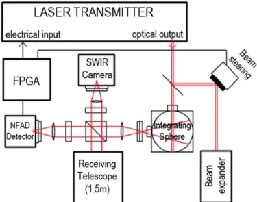
The design of the complete IPDA lidar system is shown in Fig. 1. It consists of the laser transmitter, the optics for beam transmission and reception and the control electronics. Specifically, the output beam from the transmitter is split in two branches: one is sent to the beam expander and then to the atmosphere and the other is used as reference in the comparison with the received signal, for the calculation of C02 concentration. The reflected light from Earth ground is collected by a reflective telescope with a Field of View (FOV) matching the laser beam divergence and alignment issues are addressed by using a short wave infrared (SWIR) camera.
LASER TRANSMITTER
electrical input optical output
FPGA
SWIR Camera
NFAD Detector
f<l
Receiving Telescope (1.5m)
•» TEC L A S E R C H I P 1
In
TEC
L A S E R
C H I E ^ C = l |
FSU
-«I
MOD-OFF
^
Mirror
Beam Forming Optics
V
L A S E R M O D U L E
CONTROL ELECTRONICS
optical
electrical (chip sections) electrical (TECs)
L A S E R T R A N S M I T T E R
SYSTEM CONTROL
LI DAR RECEIVER
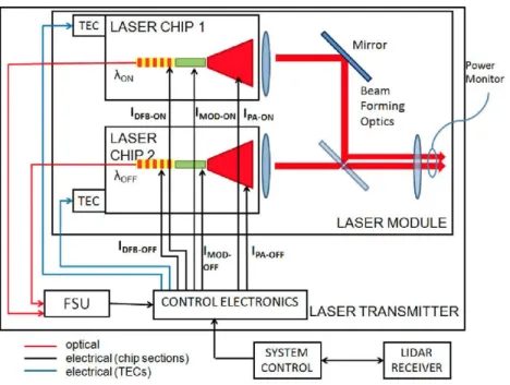
Fig. 2. Block scheme of the laser transmitter.
A very high sensitivity detector based on InGaAs negative feedback avalanche diodes (NFAD) is proposed for single photon counting of the received signal [8]. The modulation sequence and the decorrelation process required by the RM-CW technique are implemented with a Field Programmable Gate Array (FPGA).
The laser transmitter architecture is shown in Fig. 2. It consists of a space compatible Laser Module, the control electronics and the Frequency Stabilization Unit (FSU). Two Laser Chips, one for each sounding frequency (X0N, ^OFF) required for C02 detection in IPDA systems, are housed in the Laser Module, together with the beam forming optics and two power monitoring photodiodes. The back facet output of the Laser Chips are sent to the FSU through standard SMF for frequency stabilization. In the following, Laser Chips, Laser Module and FSU are described in detail.
2.1 Laser Chip
A set of two InGaAsP/InP monolithic MOP As is proposed as the main building block of the Laser Transmitter. Each MOPA is a three section device, consisting of a frequency stabilized Distributed Feedback (DFB) master oscillator, a modulator section, and a tapered amplifier. The use of this original structure aims to fulfill the performances required by the IPDA system in terms of high power, frequency stability and good beam quality. In this sense, the DFB section is accurately frequency stabilized in an external opto-electrical feedback loop through the FSU (see further in the text). The modulator section is introduced for implementation of the RM-CW technique in the proposed IPDA system. Finally, the geometry of the tapered amplifier is optimized in order to provide high brightness output beam with sufficient power and beam quality.
More in detail, three different geometries are proposed for the Laser Chip implementation, which are based on: straight,
tilted and bended designs, shown in Fig. 3. The straight geometry consists of a standard structure in which the oscillator,
modulator and amplifier sections are in-line with the propagation axis and perpendicular to the output facet (i.e. the tilt angle is 0°). The tilted and bended geometries are proposed in order to minimize undesired optical feedback from the amplifier section to the DFB oscillator. In fact, standard straight monolithically integrated MOP As are typically characterized by non linear behavior due to compound cavity effects from residual reflectivity at the amplifier output facet [9, 10].
straight MOPA 7° tilted MOPA bended MOPA
Fig 3. Straight, tilted and bended geometry designs for Laser Chip fabrication.
The design of the epitaxial structure of the devices is optimized in order to decrease the internal losses, which are relevant on InP based devices, and reduce the output beam divergence in the vertical direction. It is based on a dilute slab asymmetrical cladding approach [11] and multiple Quantum Well (QW) active region. Preliminary results on fabricated broad area lasers with the mentioned epitaxial design have shown promising results in terms of low internal losses (7.3 cm"1), low threshold current density (<480 Acm"2), low vertical divergence (32°) and high internal quantum efficiency (93%).
2.2 Laser Module
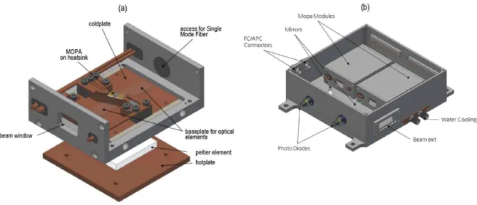
For each Laser Chip, a sub-module has been designed in order to provide electrical access, temperature control and beam forming optics for each MOPA. Figure 4 shows the design of a sub-module and the complete module, in Figs. 4 a) and b), respectively. The radiation emitted by the tapered amplifier is astigmatic, i.e. it has different source points (and different angles of divergence) in the fast axis (vertical direction) and slow axis (horizontal direction). Due to this characteristic an optical system for the collimation of a tapered amplifier must consist of two lenses [12]. We propose the use of a first aspheric lens and a second cylindrical lens. The first lens is for collimation of the fast axis and intermediate focusing of the slow axis. The second cylindrical lens collimate the slow axis and does not affect the fast axis beam. Considering also the tilted and bended geometries for Laser Chips, the emitter is tilted in slow axis in order to achieve perpendicular propagation.
(a) (b)
Mopa Modules
Fig. 4. Laser sub-module (a) and module (b).
The radiation emitted from the back facet of the DFB is expected to be diffraction limited, and therefore can be coupled into a lensed Single Mode Fiber (SMF) aligned to the DFB back facet.
right after the combining mirrors. Laser beam from the two Laser Chips are placed close each other at the Laser Module output, for minimizing footprint errors in IPDA detection.
2.3 Frequency Stabilization Unit
IPDA lidar systems require high frequency stabilization for accurate estimation of gas molecule concentration, in order to have precise measurement of the detected power ratio at the selected absorption line [2]. We propose the use of two opto-electrical feedback loops for the stabilization of the on- and off- channels emitted by the MOP As. A simple scheme, showing the selected design for the FSU, is presented in Fig. 5.
Feedback loop for CCL locking
DFB^, 'ON
^ S
C02 cellMonitoring output ^0N, ?i0FF
Feedback loop for offset frequency locking
Fig. 5. Block scheme of the proposed Frequency Stabilization Unit.
Light emitted from the back facet of the DFB section of the on- channel MOPA will be collected through a lensed SMF fiber and sent to a 50:50 fiber coupler. One of the output port of the coupler is sent to the on-channel locking feedback loop and the other is combined with the light emitted from the back facet of the off- channel MOPA with a second 50:50 fiber coupler. The on-channel MOPA will be locked to the selected C02 absorption line using a multi pass C02 reference cell and a custom feedback loop based on a commercially available (LaseLock, TEM Messtechnik GmbH) laser frequency locking equipment. A second feedback loop will be used to stabilize the beat note of the on- and off- channel signal at a fixed 10 GHz offset. The on- and off- channels frequency locking loops are schematically depicted in Fig. 4, where only the main components are shown: the C02 reference cell, the 10 GHz signal generator and the Phase Locked Loop (PLL), all based on the LaseLock equipment.
3. NUMERICAL SIMULATIONS
3.1 CW-RM IPDA lidar model
In this section, we derive the model for a RM-CW lidar from a simple analysis of a conventional pulsed system. In a IPDA pulsed system, the transmitted pulse power, PT(t), can be described for each channel, by P1(t)=PK(t)-8(t)*Gp(t),
where PK(t) is the pulse peak power, 8ft) is the Dirac function, Gp(t) is the shape of the transmitted laser pulse and * is
the convolution operator.
The received pulse power, PRft), can be written for each channel as PR(t) = PKft)Sft)*Gpft) *Gaft), where Ga(t) is the
atmosphere response function, given by Ga(t) = ri0-Sp-TonogAr-R2 -Sft-r) , with rj0 the optical efficiency of the receiver, Sp
the surface parameter (equal to reflectivity divided by K), Ar the area of the telescope, R the orbit altitude, Ton and Toff, the
on- line and off- line transmittance and rthe time delay from ground reflection.
In a CW-RM IPDA lidar, the transmitted signal is described with a random impulse train IIITft), given by IIIT(t)=y]akS(t-kTc) where ak is the PRBS, Tc is the period of the impulse train and k a positive integer. The received
Differently from a pulsed IPDA lidar, where the on- channel and the off- channel are transmitted and received sequentially, in a RM-CW IPDA lidar, both wavelength are transmitted and detected at the same time. Discrimination of each channel is obtained by shifting in time one code with respect to the other and by separate decoding at the receiver. The total received power is then given by:
P?or(t) = lZ-inr{t)*Gp{t)+I*-IIIr{t-AT)*Gp{t) (1)
where Pfn and Pji are the peak powers of the on- and off- channel, respectively, and AT is the time shift applied.
Finally, the background contribution is removed by correlating the received signal withIIIT(t) and its negated IIIT(t) and
subtracting:
PR = PTROT *IIIT(-t)-PTROT * WT{-1) (2)
3.2 Estimation of Signal to Noise Ratio
In the following sub-section, the noise performance of the system in space-borne scenarios is investigated. It has been identified that the major noise contributor of the proposed system will be ambient noise and detector dark noise. Similar to previous derivations, the Signal to Noise Ratio (SNR) will be first described for the pulsed approach. For the pulsed scheme, the received pulse energy Eon off is concentrated within a single range gate (main refection from the ground).
Signal shot noise is proportional to the square-root of the number of photoelectrons integrated in this range gate,
Non off ~ ^>e Eon off , in which §e denotes the photon energy to photoelectron number conversion coefficient (see Tab. 1). Ambient light and detector noise equivalent photoelectron numbers are represented by Namb and Ndet per range gate.
Following the shot-noise statistics, the SNR of the pulsed method can be approximated by:
K\WPul - on'off (i\
SNKon,off ~ . (3)
^0^off+Namb+Ndet
To compare the SNR of the CW-RM system with respect to the pulsed system, it will be assumed that both systems have the same average transmission power, which yields the same total received signal photoelectron numbers Non,off after
correlation. A CW-RM system under such conditions will receive less photoelectrons per range gate, as energy is spread over m (number of' l's in the PRBS) range gates, while the received photoelectrons counts per range gate are reduced by a factor of m. The number of photoelectrons for ambient light Namb and noise equivalent photoelectrons Ndet per gate
remain the same as the pulsed system. In the CW-RM system, the cross-correlation effectively accumulates the photoelectrons numbers for m range gates. Hence, a high level of noise photoelectrons m-Namb and m-Ndet per integration
time is to be expected. Therefore, the SNR of the RM-CW can be calculated as:
SNRRM-cw Non ( 4 )
,]2{N0^on +Nonoff + m-Namb +m-NM)
Note that in Eq. (4), the -.¡2 term in the noise term is caused by the subtraction of two correlations described in Eq. (2). Both Non and N0ff are in the noise term at the denominator, because both on- and off- channels are transmitted and
received simultaneously during each retrieval, as commented previously.
According to Eq. (4), for the CW-RM system to approach to the measurement precision of the pulsed system with similar average transmitting power, the ambient light level and detector noise need to be reduced.
The retrieval accuracy of the C 02 mixing ratio is obtained as:
worst case scenario, as the surface reflectivity used in calculations refers to that of the ocean (which has the lowest surface albedo). For measurements taken across vegetation, the C02 retrieval precision is improved.
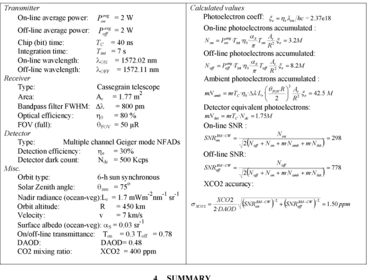
Table 1. Envelope SNR estimation for
Transmitter
On-line average power: P"^ = 2 W Off-line average power: P™g = 2 W
Chip (bit) time: Tc = 40 ns
Integration time: Tint = 7 s
On-line wavelength: X0N = 1572.02 nm Off-line wavelength: X0FF = 1572.11 nm
Receiver
Type: Cassegrain telescope
Area: Ar = 1.77 m2
Bandpass filter FWHM: AX = 800 pm Optical efficiency: r|0 = 80 % FOV (full): eF0V = 50 uR
Detector
Type: Multiple channel Geiger mode NFADs Detection efficiency: r\e = 3 0 %
Detector dark count: Ndc = 500 Kcps
Misc.
Orbit type: 6-h sun synchronous Solar Zenith angle: 8zen =75°
-2 -1 -1
Nadir radiance (ocean-veg):Lr = 1.7 mWm nm sr Orbit altitude: R =450 km
Velocity: v = 7 km/s Surface albedo (ocean-veg): as = 0.03 sr"
On/off-line transmittance: Ton = 0.3 Toff = 0.78 DAOD: DAOD= 0.48
C02 mixing ratio: XC02 = 400 ppm
a space-borne RM-CWIPDA lidar.
Calculated values
Photoelectron coeff: £ = Ve\Jhc = 2.37el8
On-line photoelectrons accumulated:
XT =p<"z.T n "^LT 4 L < 5 =3 2M "on 1 on 2mt'lo 2 on „ 2 ' e J , i l H
7T K
Off-line photoelectrons accumulated:
XT _pa*g.p .„ . 5 _ T A_e - 8 2 M
"off ~roJf Jint nil 1oJf „ 2 &e 6'Z , U 7T K
Ambient photoelectrons accumulated:
m\T -m-T -n -\1-T •[ FOV ] ' t - A^l S \4 mnamb -m Jc ' i oZ U Lr - R1 e ~
Detector equivalent photoelectrons:
mNict=m-Tc-Ndc=U5M
On-line SNR:
S\TRSM-C>r - N"" , - ?Q8
42\Nojf + Non + m-N^ + m-NiA)
Off-line SNR:
N
SNREM-CW _ "of _7 7 g
°ff ^{Kjr+Kn+nrN^+m-Nj
XC02 accuracy:
CT™ = ^DAOD^SNR"^2 + (SNRTCWY = 1-50/P»
4. SUMMARY
In this paper, we propose an all semiconductor laser source at 1.57 urn for space-borne lidar measurements of atmospheric carbon dioxide concentration. The complete design of the proposed CW-RM IPDA lidar has been presented and described in detail. Two MOP As, emitting at the sounding frequency of the on- and off- IPDA channels, are proposed as the transmitter optical sources with the required high brightness.
The complete transmitter architecture has been proposed and the laser chips, laser module and frequency stabilization unit are presented in detail. The CW-RM approach has been modeled and an estimation of the expected SNR for the entire system is presented. Promising results indicate that a C02 retrieval precision of 1.5 ppm could be achieved with an
average output power of 2 W for each channel.
ACKNOWLEDGEMENT
REFERENCES
[1] http://www.britespace.eu/
[2] G. Ehret, C. Kiemle, M. Wirth, A. Amediek, A. fix And S. Houweling., "Space-borne remote sensing of C02, CH4, and N20 by integrated path differential absorption lidar: a sensitivity analysis" Applied Physics B, 90 (3-4), 593-608 (2008).
[3] Browell, E., S. Ismail, and W. Grant, "Differential absorption lidar (DIAL) measurements from air and space" Applied Physics B, 67(4), 399-410 (1998).
[4] Fix, A., et al., "Water vapor differential absorption lidar measurements using a diode-pumped all-solid-state laser at 935 nm" Applied Physics B, 102(4), 905-915 (2011).
[5] Numata, K., et al., "Frequency stabilization of distributed-feedback laser diodes at 1572 nm for lidar measurements of atmospheric carbon dioxide" Applied Optics, 50(7), 1047-1056 (2011).
[6] Fox, B.P., et al., "Gamma-radiation-induced photodarkening in unpumped optical fibers doped with rare-earth constituents" IEEE Transactions on Nuclear Science, 57(3), 1618-1625 (2010).
[7] Ai, X., et al., "High-resolution random-modulation cw lidar" Applied Optics, 50(22), 4478-4488 (2011). [8] Ai, X., et al "Pseudo-random Single Photon Counting for Space-borne Atmospheric Sensing Applications".
IEEE Aerospace Conference 2014. Big Sky, Montana, USA.
[9] M. Spreemann, M. Lichtner, M. Radziunas, U. Bandelow, and H. Wenzel, "Measurement and simulation of distributed feedback tapered master-oscillator power-amplifiers" IEEE Journal of Quantum Electronics 45(6), 609-616 (2009).
[10] S. Bauer, O. Brox, J. Kreissl, B. Sartorius, M. Radziunas, J. Sieber, H. J. Wünsche, and F. Henneberger, "Nonlinear dynamics of semiconductor lasers with active optical feedback," Phys. Rev. E 69, 016206 (2004). [11]M. Faugeron, M. Tran, O. Parillaud, M. Chtioui, Y. Robert, E. Vinet, A. Enard, J. Jacquet, and F. Van Dijk,
"High-Power Tunable Dilute Mode DFB Laser With Low RIN and Narrow Linewidth", IEEE Photonics Technology Letters, 25(1), 7-10 (2013).
[12] Gerd Kochem; Mark Haverkamp ; Konstantin Boucke, "Frequency stabilized high brightness tapered amplifier and laser modules " Proc. SPIE 6997 (2008)