layer may be a dark-coloured coat of up to 0.1 mm in thickness. A transparent covering layer of water, glass or artificial resin makes it possible to limit a volume increase and through-depth compression directing. A usual thickness of the covering médium ranges between 2 and 4 mm or more. The láser beam applied to material shock processing shall be of a pulsed type and of high energy; the energy of an individual pulse usually ranges between some joules to some tens of joules, and exceptionally up to some 100 joules. The efficiency of transformation into the mechanical energy will increase with a high-power density and short pulse duration. This requires an accurate source and amplification of the láser beam. Typical pulse duration ranges between 0.6 and 30 nanoseconds, and power density is equal to more than 1 x 10⁹ and over 100 x 109 W/cm2. The process efficiency will be increased by short pulses of high-power density. The laser-beam diameter in practical applications usually ranges between 0.1 and 3.0 mm and more, and it is limited primarily by the laser-source power.
The effects of mechanical shock waves are similar to those of shot peening. The density of dislocations and, consequently, dynamic strength of the material will increase. LSP is essentially more expensive than shot peening, but it provides some advantages, e.g., the possibility of an accurate control of processing parameters and accomplishment of different transitions between the treated surface and the untreated one.
Shock-wave processing based on the pulsed láser has been discussed in several publications. Initially, publications discussed mainly the theoretical aspects, but the advancement of technical facilities has permitted studies on an increasingly large number of materials. Modelling of LSP was discussed, e.g., by Gámez and Ocaña (2000) and Fazal and Arif (2003), who described the key processing parameters using a model of computer simulation of the affected-layer depth and residual stresses in this layer.
Ocaña et al. (2004) discussed the influence of LSP on the increase of wear resistance of metáis and metal alloys. The comprehensive research work also discussed plasma generation and a mode of a shock-wave propagation into the subsurface layers. Berthe et al. (2000) discussed the generation of plasma and shock waves from the viewpoint of physics under the circumstances in which wave propagation was directed and amplified by means of a covering layer of water. Also, Sollier et al. (2001) dealt with a physical description of a numerical plasma model in LSP. They particularly focused on the plasma changes in the final phase of laser-beam action, when the laser-beam energy transfer to the material surface is shadowed (»breakdown plasma«).
Montross et al. (2002) discussed residual intemal stresses in a metal material after LSP. A theoretical approach to the occurrence of compressive residual stresses was supplemented with a discussion of the influence of individual parameters on the process, Le., of laser-radiation wavelength X, number of pulses, laser-spot size. Very interesting results were found in the wear of 7075-T7351 aluminium alloy after láser processing and classical processing. It was found that LSP provided an operating life that is several times longer.
2 Experimental procedure
2.1 Preparation ofspecimens and measurements
microhardness and residual stresses. The material chosen for this purpose was maraging steel with 12% of Ni and a Co-Mo-Ti system for precipitation hardening. The maraging steel was in as-delivered state which means that it was solution-annealed and homogenised by forging. The initial microstructure of samples was saturated nickel martensite with hardness of 30 HRC to 32.5 HRC.
The specimens were cut out of a rod; the discs cut of 3.5 mm in thickness were ground and then cut with a grinder to their final size, Le., 60 x 30 x 2.5 mm. Both prior to and after LSP, the following measurements were carried out at each specimen:
• surface roughness (general assessment of surface quality, measurement of mean deviation of the profile Ra)
• microhardness (HV2.0)
• through-depth profile of residual stresses (hole-drilling method) • assessment of microstructure using optical and electronic microscopes.
LSP was performed using four different combinations of basic parameters. The combination of láser beam diameter and pulse densities is shown in Table 1. Measurements from within LSP-treated zone are additionally marked with 'ob' while measurements from non-treated zone are marked with 'n'.
Table 1 Combinations of basic parameters for LSP
Designation Beam diameter [mm] Pulse density [pulses/cm ]
1 1.5 1225 2 1.5 5000 3 2.0 1225 4 2.0 5000 After LSP, precipitation hardening was performed in a classical furnace at temperatures
of 410°C, 450°C and 490°C for two hours. Precipitation annealing may drastically change the initial microstructure with precipitates that form within the nickel martensite. With the selected type of maraging steel different types of precipitated phases are present, such as Fe2Mo, Ni3Ti, Ni3Mo, TiC, TiN and others. These precipitated phases significantly change mechanical and other properties, the most evident being higher strength and hardness. Microstructure is described in more detall by Grum and Zupancic (2002) with preceding tests and results explained for conventional precipitation hardening of the discussed maraging steel.
Finally, after precipitation annealing, a third set of measurements followed. 2.2 Residual stresses after shock processing
theory of heat transfer. With pulsed heating used in such a treatment, the temperature as a function of linear coordínate x, time t, material properties, and supply of heat flow by the laser-beam can be expressed as a non-linear differential equation of the second order, as explained by Montross et al. (2002). A fast temperature increase will result in rapid expansión at the point of interaction of the láser beam with the surface, the V being the velocity of moving away of the surface, which is a result of expansión and can be determined from the energy equilibrium in the zone of interaction, and Lev is the latent heat consumed in the evaporation of the absorption layer. Considering the mode of calculation, boundary conditions and the limitations taken into account in modelling, the calculation of basic quantities may be very complex. A complete analytical solution of such an equation for non-uniform boundary conditions of evaporation is not possible; a partial solution, however, can be applied using the Laplace transformation of the equation of temperature in time.
The through-depth propagation of the mechanical shock wave in the material produces local plástic deformation at the micro level that, in turn, produces a local change of the dislocation density. The plástic deformation will occur to the depth where the shock wave can still cross the so-called Hugoniot's Elastic Limit (HEL), also dealt with by Johnson and Rhode (1971). The magnitude of the stress owing to the compressive shock-wave is conditioned exclusively by the material properties, Le., the dynamic yield strength and Poisson's ratio. A higher Poisson's ratio will require a higher shock-wave compression. As maraging steel has a similar Poisson's ratio as common steel, this means that the shock-wave compression should be approximately 70% higher than the dynamic yield strength to achieve plástic deformation.
The stresses in the surface layer can be determined according to Ballard et al. (1991). The magnitude of the residual stresses in the thin surface layer owing to shock waves depends on the material properties (Lame constants, the velocity of elastic and plástic deformation) and on the process conditions (time of compres sive-wave interaction, beam radius at the surface, shock-wave compression). Changes in the processing parameters that increase the stresses in the surface layer are primarily the lengthening of the time of interaction, increases in beam diameter and shock-wave compression. The fulfilment of these requirements is in opposition to the requirements for the achievement of a greater affected depth: thus for example, a larger beam radius will require a shorter time of interaction if the same energy density is to be kept.
In practice, the residual stresses in the surface layer owing to LSP can differ considerably and can range between 0 and the yield stress of the material concerned. The equations for calculations are considered valid under the condition that puv > 2 HEL. When this condition is fulfilled, the compression will certainly be strong enough to produce the effects desired.
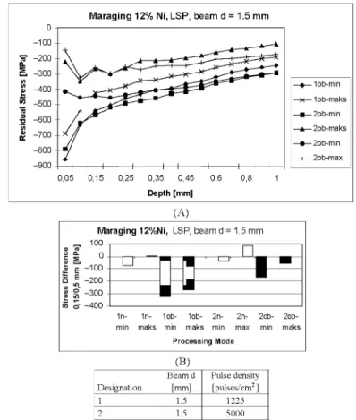
Figure 1 shows the LSP conditions, the measured residual-stress profiles and a through-depth stress gradient, the láser beam used having a diameter of 1.5 mm. The residual-stress profile after LSP was changed considerably. The stress profiles shifted to the compressive zone to depths exceeding 0.2 mm, a smaller influence being seen also in a depth exceeding 1 mm (Figure 1A). Figure 1(B) shows the differences among residual stresses in the 0.15 mm thick surface layer and those in the chosen reference depth of 0.5 mm; an essential increase in the through-depth stress gradient may be observed. An increase in compressive residual stresses is desired, but the through-depth stress gradient should not be too high because it may produce microcracks and, in exceptional cases, also peeling of the surface layer.
Figure 1 (A) Residual-stress profiles after LSP. (B) Differences among stresses in 0.15 mm thick surface layer and those in depth of 0.5 mm after LSP with 1.5 mm beam
Maraging 12% Ni, LSP, beam d = 1.5 mm
—4— 1ob-m¡n
—x— 1ob-maks —•—2ob-m¡n
A 2ob-maks
—•—2ob-m¡n —i—2ob-max
0,05 0,15 0,25 0,35 0,45 0,6 0,8 1
Depth [mm]
(A)
Maraging 12%N¡, LSP, beam d = 1.5 mm
0) " o o. S i. £ E
° J .. f>
1!
100 0 -100 -200 -300 -400
1n- 1n- 1ob- 1ob- 2n- 2n- 2ob-min maks 2ob-min maks 2ob-min max 2ob-min maks
Processing Mode
(B)
Designation 1 2
Beam d [mm]
1.5 1.5
Pulse density [pulses/cm2 ]
1225 5000
Note: Measurements from within LSP-treated zone are marked with 'ob' while measurements from non-treated zone are marked with 'n'.
The angle of the principal residual stresses can be an indicator of the changes occurring during the treatment in the surface layer. The angles of the principal stresses are, similarly to stress profiles after LSP, essentially changed with reference to the initial state. The depths where stronger changes of the angle occur are those where during LSP, changes of the stress state have occurred.
Figure 2(A) shows the residual-stress profiles and the gradient of the residual stresses in the surface layer after LSP, the laser-beam diameter being 2.0 mm. The residual-stress profile is similar to the first case, which means that no essential difference caused by the change of beam diameter could be noticed. But there is a great difference owing to the number of pulses, Le., density, during the treatment with 1225 pulses/cm2 and that of 5000 pulses/cm2. The residual stresses under Conditions 3, where the pulse density used was 1225 pulses/cm2, are absolutely smaller than those under Conditions 4, where the pulse density used was 5000 pulses/cm2. The gradients of the residual stresses in different depths (Figure 2B) are considerably greater than before LSP also in the case of the 2.0 mm láser beam. From a comparison of the data on the residual stresses, it can be inferred that the influence of the laser-beam size is comparatively small whereas the influence of pulse density on the residual stresses is very strong.
Figure 2 (A) Residual-stress profiles after LSP. (B) Differences among stresses in 0.15 mm thick surface layer and those in depth of 0.5 mm after LSP with 2.0 mm beam
0 1 0 0
ra" 2 0 0
-0.
i . 3 0 0 8 4 0 0 *> 5 0 0 -re ^ 6 0 0
-i/)
£ 7 0 0 8 0 0
-Maraging 12% Ni, LSP, beam =
.V^^^^r^s
*—'^7^--^^
/ ^-^^*^*^^
0.05 0.15 0.25 0.35 0.45 0.6 Depth [ m m ]
2.0 mm
S = 3 5 ^
I I I
—A—3ob-min
-^K—3ob-max
—#—4ob-min
-^x—4ob-max —I—4ob-min
—-— 4ob-max
0,8 1
(A)
2 ¡o 55 S" -400
Maraging 12%N¡, LSP, beam d = 2.0 mm
100 0 -•100 •200 •300 Processing Mode (B) Designa tion Beam d [mm] Pulse density [pulses/cm2] 2.0
2.0
1225 5000
The residual stresses in the surface layer, if compared to the stress in the depths of 0.50 mm and 1.00 mm respectively, are considerably higher after LSP than before processing. The differences are smaller if the surface layer of a greater thickness (0.15 mm) is compared to a smaller reference depth (0.50 mm); on the contrary, they are greater if the thin surface layer (0.10 mm) is compared to a greater reference depth (1.00 mm). High compressive stresses in the surface layer are otherwise desired, but in this case they also show a high through-depth gradient of stresses, which is not quite favourable.
The conditions in the surface layer after LSP and additional precipitation annealing are shown in Figure 3. The profiles of the principal residual stresses are lying in a completely compressive zone and can be, in the surface layer, cióse to the yield stress of the material chosen. As anticipated, a greater number of the pulses employed in LSP increases the depth affected. Figure 3 (A) shows the profiles measured of the minimum residual stresses after LSP with the 1.5 mm beam and the number of pulses being 1225 cm~2 and 5000 cm"2 and additional annealing at 410°C for two hours. A greater number of pulses produces a considerable increase of the depth affected and, consequently, a similar or even lower stress gradient in the surface layer. With the specimens treated with the 2.0 mm beam after precipitation annealing, the affected depth is much greater with a higher pulse density, and the stress gradient in the surface also increases a little, as shown in Figure 3(B). Thus it can be confirmed that a greater number of pulses during LSP with given processing parameters and material employed does not necessarily increase the magnitude of the residual stresses in the surface layer, but it has a favourable influence on the residual-stress profile and increases the depth affected. Figure 3 Residual-stress profiles after LSP and additional precipitation annealing in furnace
at 410°C/2 h
(A) Minimum stresses after LSP with (B) 2.0 mm beam and 1225 pulses/ 1.5 mm beam and 1225 pulses/cm2 cm2 (parameters 3) and (processing parameters 1) and 5000 pulses/cm2 (4) 5000 pulses/cm2 (2)
2.3 Microhardness after LSP and precipitation annealing
precipitation annealing in the furnace. Increasing of microhardness in the surface layer can be observed to a depth of approximately 0.5 mm (Figure 4A). This increase in microhardness in the surface layer after LSP is true for processing conditions with LSP (Conditions 1, 2, 3 and 4). After the additional precipitation annealing, hardness will increase both in the affected surface layer and in a greater depth. The change of microhardness is different with different modes of processing. If measurement deviations that may occur because of a small load in microhardness measurement are excluded, this may be explained by the influence on the formation of the phases precipitated, which may, owing to the effects of shock waves, precipítate at several locations with an increased density of dislocations. This results in a greater density of the precipitated phases, which are on the average smaller and increase microhardness to a smaller degree than in the greater depth.
Figure 4 Microhardness (HV2.0) after LSP (A) and after additional precipitation annealing at 410°C (B), 450°C (C) and 490°C (D) for two hours
Microhardness after LSP LSP + 4 1 0 ° C / 2 h
0,5 1 1,5 Depth [mm]
0,5 1 1,5 Depth [mm]
(A)
(B)
LSP + 450°C / 2h LSP + 490°C / 2h
600
500
400
300
200
d1 « A * * í • "
* "4« • • • * A
(C)
600
500
400
300
200
1 * ^ x 1
-r i
f * ! I
<
?rr*
\
_ • *
i
i
i
"
1 A "
0 0,5 1 1,5 2 Depth [mm]
0 0,5 1 1,5 2 Depth [mm]
(D)
The individual microhardness diagrams show stronger changes between the hardness in the depth of 0.5 mm and that in a depth exceeding 1 mm; it can be observed that shock waves produce a change of microhardness also after precipitation annealing which is, however, smaller with higher temperature of precipitation annealing.
The difference between the results obtained for the microhardness in the affected surface layer and those obtained in the core was statistically evaluated. A t-test was applied to a various number of microhardness measurements at the individual specimens in the surface layer and in the layer in the greater depth (exceeding 0.5 mm). A normal distribution of microhardness results and a mutual independence of the results of the two groups compared were presupposed. The statistical tests of the differences between the surface layer and the core showed that there was a significant difference in microhardness between the affected layer and the core both before and after precipitation annealing. For the hardness found immediately after LSP and after precipitation annealing at 410°C and 450°C significant differences were confirmed with a probability of error of 0.05. After precipitation annealing at 490°C, the probability that the difference is not significant equals 0.15.
3 Conclusions
LSP has turned out to be a very promising way of treatment in order to improve surface properties of structural and tool materials. Shock waves produce locally oriented mechanical waving, propagating through the material depth. This results in changes of the material microstructure, including through-depth changes of dislocation density owing to the effects of shock waves.
The purpose of the tests performed on 12% maraging steel was to evalúate some of the hardening effects of LSP on the thin surface layer of the chosen maraging steel. The residual stresses after LSP are shifted to the compressive zone. High valúes of the residual stresses after LSP were present down to the depth of about 0.25 mm, but changes were visible also in the depth over 0.50 mm. The pulse density increases the absolute valúes of residual stresses and makes sure that the transition from the compressive zone to the tensile one will occur in a greater depth. Consequently, owing to the greater affected depth, even lower gradients of residual stresses in the thin surface layer may be obtained.
References
Ballard, P., Fournier, J., Fabbro, R. and Frelat, J. (1991) 'Residual stresses induced by láser shocks', Journal de Physique, Vol. IV, No. 1, pp.487^-94.
Berthe, L., Sollier, A., Peyre, P., Fabbro, R. and Bartnicki, E. (2000) 'The generation of láser shock waves in a water-confinement regime with 50 ns and 150 ns XeCl excimer láser pulses', J. Phys. D: Appl. Phys., Vol. 33, pp.2142-2145.
Fazal, A. and Arif, M. (2003) 'Numerical prediction of plástic deformation and residual stresses induced by láser shock processing', Journal of Materials Processing Techn., Vol. 136, pp.120-138.
Gámez, B. and Ocaña, J.L. (2000) 'A theoretical method for the calculation of frequency- and temperature-dependent interaction constants applicable to the predictive assessment of láser materials processing', /. Phys. D: AppliedPhysics, Vol. 33, pp.305-312.
Grum, J. and Zupancic, M. (2002) 'Suitability assessment of replacement of conventional hot-working steels with maraging steel. Part 2, microstructure of maraging steel after precipitation hardening treatment', Z. Met.kd., Vol. 93, No. 2, pp.171-176.
Johnson, J.N. and Rhode, R.W. (1971) 'Dynamic deformation twinning in shock loaded iron', Journal of Applied Physics, Vol. 42, pp.4171^1182.
Montross, C.S., et al. (2002) 'Láser shock processing and its effects on microstructure and properties of metal alloys: areview', International Journal of Fatigue, Vol. 24, pp.1021-1036. Ocaña, J.L., Morales, M., Molpeceres, C , Torres, J., Porro, J.A., Gómez, G. and Rubio, C. (2004) 'Predictive assessment and experimental characterization of the inñuence of irradiation parameters on surface deformation and residual stresses in láser shock processed metallic alloys', Proceedings ofthe SPIE, Vol. 5448, pp.642-653.