DIPLOMADO DE PROFUNDIZACION CISCO PRUEBA DE HABILIDADES PRÁCTICAS CCNP
ELISEO ANGEL RODRIGUEZ SANABRIA
Diplomado de opción de grado presentado para optar el título de INGENIERO DE TELECOMUNCACIONES
DIRECTOR:
MSc. GERARDO GRANADOS ACUÑA
UNIVERSIDAD NACIONAL ABIERTA Y A DISTANCIA - UNAD ESCUELA DE CIENCIAS BÁSICAS, TECNOLOGÍA E INGENIERÍA - ECBTI INGENIERÍA DE
TELECOMUNICACIONES BARRANQUILLA
NOTA DE ACEPTACIÓN
Firma del presidente del Jurado
Firma del Jurado
Firma del Jurado
3
CONTENIDO
CONTENIDO...3
LISTA DE TABLAS ...4
LISTA DE FIGURAS ...5
INTRODUCCION...7
RESUMEN...8
DESARROLLO ...9
1. Escenario 1 ...10
2. Escenario 2 ...41
CONCLUSIONES ...84
4
LISTA DE TABLAS
5
LISTA DE FIGURAS
FIGURA 1APLICAMOS EL SCRIPT DE CONFIGURACIÓN ... 11
FIGURA 2CONFIGURACIÓN APLICADA EN R2 ... 12
FIGURA 3CONFIGURACIÓN APLICADA EN R3 ... 13
FIGURA 4CONFIGURACIÓN APLICADA EN R1. ... 13
FIGURA 5CONFIGURACIÓN APLICADA EN R2 ... 14
FIGURA 6CONFIGURACIÓN APLICADA EN R3 ... 14
FIGURA 7CONFIGURACIÓN APLICADA EN R2 ... 15
FIGURA 8CONFIGURACIÓN APLICADA EN R3 ... 15
FIGURA 9CONFIGURACIÓN APLICADA EN R2 ... 16
FIGURA 10CONFIGURACIÓN APLICADA EN R3 ... 16
FIGURA 11CONFIGURACIÓN APLICADA EN R2. ... 17
FIGURA 12CONFIGURACIÓN APLICADA EN R3 ... 17
FIGURA 13CONFIGURACIÓN APLICADA EN R1 ... 18
FIGURA 14CONFIGURACIÓN APLICADA EN R2 ... 19
FIGURA 15CONFIGURACIÓN EIGRP EN R1 SE REPLICA EN R2,R3 ... 19
FIGURA 16CONFIGURACIÓN APLICADA EN R2 ... 20
FIGURA 17CONFIGURACIÓN APLICADA EN R3 ... 20
FIGURA 18CONFIGURACIÓN APLICADA EN R2 ... 21
FIGURA 19CONFIGURACIÓN APLICADA EN R2 ... 21
FIGURA 20VERIFICACIÓN DE LOS PROTOCOLOS ... 22
FIGURA 21VERIFICACIÓN DE LOS PROTOCOLOS ... 22
FIGURA 22VERIFICACIÓN DE LOS PROTOCOLOS ... 23
FIGURA 23VERIFICACIÓN DE LOS PROTOCOLOS 1 ... 23
FIGURA 24MOSTRANDO LOS VECINOS CONECTADOS ... 24
FIGURA 25VERIFICACIÓN DE LOS PROTOCOLOS DE ENRUTAMIENTO ... 25
FIGURA 26VERIFICACIÓN DE LOS PROTOCOLOS ... 25
FIGURA 27 VERIFICACIÓN DE PROTOCOLO DE ENRUTAMIENTO VECINO ... 26
FIGURA 28 PING A TRAVÉS DE TCLSH. ... 26
FIGURA 29 CONTINUACIÓN FIG.30 ... 27
FIGURA 30 CONTINUACION FIG.30 ... 28
FIGURA 31 CONTINUACION FIG.30 ... 29
FIGURA 32 CONTINUACION FIG.30 ... 30
FIGURA 33 VERIFICACION DE RUTAS FILTRADAS ... 31
FIGURA 34 CONTINUACION FIG.33 ... 32
FIGURA 35 CONTINUACION FIG.33 ... 33
FIGURA 36 CONTINUACION FIG.33 ... 34
FIGURA 37 CONTINUACION FIG.33 ... 35
FIGURA 38 CONTINUACION FIG.33 ... 36
FIGURA 39 CONTINUACION FIG.33 ... 37
FIGURA 40 VERIFICACION DE RUTAS FILTRADAS ... 38
FIGURA 41 CONTINUACION DE FIGURA 42 ... 39
FIGURA 42APAGAR RANGO DE INTERFACES ... 42
FIGURA 43CONFIGURACIÓN APLICADA EN DLS2 ... 42
FIGURA 44CONFIGURACIÓN APLICADA EN ALS1 ... 43
FIGURA 45CONFIGURACIÓN APLICADA EN ALS2 ... 43
6
FIGURA 47 DE ACUERDO AL ESCENARIO CREAMOS ETHERCHANNEL EN LOS PUERTOS ... 44
FIGURA 48 DE ACUERDO AL ESCENARIO CREAMOS ETHERCHANNEL EN LOS PUERTOS ... 44
FIGURA 49 DE ACUERDO AL ESCENARIO CREAMOS ETHERCHANNEL EN LOS PUERTOS ... 45
FIGURA 50 DE ACUERDO AL ESCENARIO CREAMOS ETHERCHANNEL EN NEGOCIACIÓN EN LOS PUERTOS ... 45
FIGURA 51 DE ACUERDO AL ESCENARIO CREAMOS ETHERCHANNEL ACTIVO EN LOS PUERTOS ... 46
FIGURA 52 DE ACUERDO AL ESCENARIO CREAMOS ETHERCHANNEL EN NEGOCIACIÓN EN LOS PUERTOS ... 46
FIGURA 53 DE ACUERDO AL ESCENARIO CREAMOS ETHERCHANNEL ACTIVO EN LOS PUERTOS ... 47
FIGURA 54 DE ACUERDO AL ESCENARIO CREAMOS ETHERCHANNEL ACTIVO EN LOS PUERTOS ... 47
FIGURA 55 DE ACUERDO AL ESCENARIO CREAMOS ETHERCHANNEL EN NEGOCIACIÓN EN LOS PUERTOS ... 48
FIGURA 56 ASIGNACIÓN DE IP AL PUERTO PO 12 ... 48
FIGURA 57 ASIGNACIÓN DE IP AL PUERTO PO 12 ... 48
FIGURA 58 CONFIGURACIÓN DEL RANGO DE PUERTOS COMO LACP ... 49
FIGURA 59 CONFIGURACIÓN DEL RANGO DE PUERTOS COMO LACP ... 49
FIGURA 60 CONFIGURACIÓN DEL RANGO DE PUERTOS COMO LACP ... 49
FIGURA 61 CONFIGURACIÓN DEL RANGO DE PUERTOS COMO LACP ... 50
FIGURA 62 CONFIGURACIÓN DEL RANGO DE PUERTOS COMO PAGP ... 50
FIGURA 63 CONFIGURACIÓN DEL RANGO DE PUERTOS COMO PAGP ... 50
FIGURA 64 CONFIGURACIÓN DEL RANGO DE PUERTOS COMO PAGP ... 50
FIGURA 65 CONFIGURACIÓN DEL RANGO DE PUERTOS COMO PAGP ... 51
FIGURA 66 ASIGNACIÓN DE PUERTOS A LA VLAN 800 ... 51
FIGURA 67 ASIGNACIÓN DE PUERTOS A LA VLAN 800 ... 52
FIGURA 68 ASIGNACIÓN DE PUERTOS A LA VLAN 800 ... 52
FIGURA 69 ASIGNACIÓN DE PUERTOS A LA VLAN 800 ... 53
FIGURA 70 ACTIVACIÓN DE VTP VERSIÓN 3 ... 53
FIGURA 71 ACTIVACIÓN DE VTP VERSIÓN 3 ... 53
FIGURA 72FIGURA 72 ACTIVACIÓN DE VTP VERSIÓN 3 ... 54
FIGURA 73 CONFIGURACIÓN DLS1 COMO SERVIDOR PARA LAS VLAN ... 54
FIGURA 74 CONFIGURACIÓN DE COMO VTP CLIENTE ... 54
FIGURA 75 CONFIGURACIÓN DE COMO VTP CLIENTE ... 54
FIGURA 76 CREACIÓN DE VLAN´S SEGÚN TABLA 2 ... 56
FIGURA 77 COLOCAR LA VLAN 434 COMO SUSPEND... 56
FIGURA 78 CONFIGURAR VTP VERSIÓN 2 Y LAS VLAN SEGÚN TABLA 1 EN DLS2. ... 57
FIGURA 79 COLOCAR LA VLAN 434 COMO SUSPEND... 58
FIGURA 80 CREACIÓN DE LA VLAN 534 EN DLS2 ... 58
FIGURA 81 CREACIÓN SPANNING TREE ROOT... 58
FIGURA 82 CREACIÓN SPANNING TREE ROOT... 59
FIGURA 83 CONFIGURAR LOS PUERTOS COMO TRONCAL ... 59
FIGURA 84 CONFIGURAR LOS PUERTOS COMO TRONCAL ... 59
FIGURA 85 CONFIGURAR LOS PUERTOS COMO TRONCAL ... 59
FIGURA 86 CONFIGURAR LOS PUERTOS COMO TRONCAL ... 60
FIGURA 87 CONFIGURAR LAS INTERFACES COMO PUERTO DE ACCESO ... 60
FIGURA 88 CONFIGURAR LAS INTERFACES COMO PUERTO DE ACCESO ... 61
FIGURA 89 CONFIGURAR LAS INTERFACES COMO PUERTO DE ACCESO ... 62
FIGURA 90 CONFIGURAR LAS INTERFACES COMO PUERTO DE ACCESO ... 63
FIGURA 91 CONFIGURAR LAS INTERFACES COMO PUERTO DE ACCESO ... 64
FIGURA 92 VERIFICACIÓN DE LA CONFIGURACIÓN APLICADA ... 65
FIGURA 93 VERIFICACIÓN DE LA CONFIGURACIÓN APLICADA ... 65
FIGURA 94 VERIFICACIÓN DE LA CONFIGURACIÓN APLICADA ... 66
FIGURA 95 VERIFICACIÓN DE LA CONFIGURACIÓN APLICADA ... 66
FIGURA 96 VERIFICACIÓN DE LA CONFIGURACIÓN APLICADA ... 75
7
INTRODUCCION
En la presente prueba de habilidades demostraremos destrezas adquiridas a lo largo del curso en ciertos temas como son: (OSPF) el cual requiere solo unos pocos comandos relativamente simples cuando utilizándolo en una red pequeña a mediana. Sin embargo, detrás de esos comandos reside en un protocolo de enrutamiento bastante complejo, con elementos internos que pueden intimidar a los nuevos OSPF. En comparación con el Protocolo de enrutamiento de puerta de enlace interior mejorado menos complejo (EIGRP), OSPF requiere más reflexión al planificar y algunos comandos de configuración más. Adicionalmente, la subyacente complejidad de OSPF hace operando y verificar Un OSPF entre redes Más desafiante.
LACP es una alternativa basada en estándares para PAgP, definida en IEEE 802.3ad (también conocida como IEEE 802.3 Cláusula 43, "Agregación de enlaces"). Los paquetes LACP se intercambian entre conmuta a través de puertos con capacidad EtherChannel. Al igual que con PAgP, los vecinos se identifican y las capacidades del grupo de puertos se aprenden y se comparan con las capacidades del conmutador local, Sin embargo, LACP también asigna roles a los puntos finales de EtherChannel.
8
RESUMEN
En el presente trabajo se analiza la implementación del protocolo OSPFv3, EIGRP, PAgP, LACP, así como los obstáculos que los administradores de red se encuentran para la migración de redes IPv4 a redes nativas de IPv6. El movimiento hacia IPv6 está actualmente efectuado con proveedores de servicio, algunos de ellos están muy cerca de la fase de implementación. Muchas organizaciones de gobierno (en los Estados Unidos) también han recibido mandatos para migrar sus sistemas en anticipación a la necesidad de soportar el protocolo IPv6. La mayoría de las empresas y organizaciones de gobierno no están listas para implementar el IPv6, aún están en las etapas de evaluación o planeación debido a la falta de conciencia y entendimiento de cómo manejar la transición de este dispositivo. Sin embargo, eventualmente estas empresas deben hacer el cambio debido a que sus usuarios, empleados y clientes lo demandarán. Los usuarios y nuevos dispositivos que utilizarán IPv6, manejarán este proceso de transformación.
9
DESARROLLO
Escenario 1
Una empresa de confecciones posee tres sucursales distribuidas en las ciudades de Bogotá, Medellín y Bucaramanga, en donde el estudiante será el administrador de la red, el cual deberá configurar e interconectar entre sí cada uno de los dispositivos que forman parte del escenario, acorde con los lineamientos establecidos para el direccionamiento IP, protocolos de enrutamiento y demás aspectos que forman parte de la topología de red.
Topología de red
10
Introducción al Escenario 1.
Este escenario basado en habilidades (SBA) corresponde al desempeño práctico final de la formación de la Academia para el curso CCNPv7 ROUTE.
En la Parte 1, se configura los protocolos de ruteo múltiples, nombrados EIGRP, OSPFv3 para crear una red integrada. En la Parte 2, usted crea un script Tcl para probar la Conectividad Del IPv4 y del IPv6 y utiliza los comandos traceroute y show para verificar el ruteo y la selección de la trayectoria. escenario combina la configuración del dispositivo y la solución de problemas.
Objetivos.
Parte 1: Configurar los routers en la topología de acuerdo con el diagrama y las especificaciones proporcionadas.
Parte 2: Probar la red para obtener la conectividad y el control de ruta adecuados.
Parte 1: Configure la red de acuerdo con las especificaciones.
1. Configurar las interfaces con las direcciones IPv4 e IPv6 que se muestran en la topología de red.
11
Comandos que debemos ingresar
Enable (para ingresar a modo privilegiado)
conf terminal (para ingresar al modo de configuración global) hostname R1 (asignamos el nombre el dispositivo)
ipv6 unicast-routing (habilitamos ipv6 en el dispositivo) int S2/0 (ingresamos a la interfaz a configurar)
ip add 192.168.9.1 255.255.255.252 (asignamos la dirección correspondiente) no sh (encendemos la interfaz que viene apagada por defecto)
ipv6 add 2001:db8:acad:90::1/64 (asignamos la dirección ipv6 correspondiente) ipv6 add fe80::1 link-local (asignamos la dirección link local correspondiente) exit (salimos de la interfaz)
int E0/0
ip add 192.168.110.1 255.255.255.0 ipv6 add 2001:db8:acad:110::1/64 no sh
Figura 1 Aplicamos el script de configuración
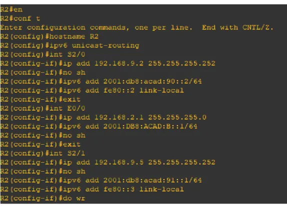
R2
en
conf terminal hostname R2 ipv6 unicast-routing int S2/0
12
ipv6 add 2001:db8:acad:90::2/64 ipv6 add fe80::2 link-local
exit int E0/0
ip add 192.168.2.1 255.255.255.0 ipv6 add 2001:db8:acad:b::1/64 no sh
exit int S2/1
ip add 192.168.9.5 255.255.255.252 no sh
ipv6 add 2001:db8:acad:91::1/64 ipv6 add fe80::3 link-local
Figura 2 Configuración aplicada en R2
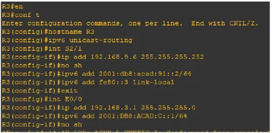
R3
en conf t
13
ip add 192.168.9.6 255.255.255.252 no sh
ipv6 add 2001:db8:acad:91::2/64 ipv6 add fe80::3 link-local
exit int E0/0
ip add 192.168.3.1 255.255.255.0 ipv6 add 2001:db8:acad:c::1/64 no sh
Figura 3 Configuración aplicada en R3
2. Ajustar el ancho de banda a 128 kbps sobre cada uno de los enlaces seriales ubicados en R1, R2, y R3 y ajustar la velocidad de reloj de las conexiones de DCE según sea apropiado.
R1
int S2/0 (ingresamos a la interfaz a configurar)
clock rate 128000 (asignamos el dispositivo como DCE) bandwidth 128 (asignamos el ancho de banda a la interfaz)
Figura 4 Configuración aplicada en R1.
14
int S2/1
clock rate threshold 128000 (asignamos el dispositivo como DCE) bandwidth 128
int S2/0
bandwidth 128
Figura 5 Configuración aplicada en R2
R3
int S2/1
bandwidth 128
Figura 6 Configuración aplicada en R3
3. En R2 y R3 configurar las familias de direcciones OSPFv3 para IPv4 e IPv6. Utilice el identificador de enrutamiento 2.2.2.2 en R2 y 3.3.3.3 en R3 para ambas familias de direcciones.
R2
router ospfv3 1 (ingresamos al protocolo de enrutamiento según escenario) address-family ipv4 unicast
router-id 2.2.2.2 exit-address-family
address-family ipv6 unicast router-id 2.2.2.2
15
Figura 7 Configuración aplicada en R2
R3
router ospfv3 1
address-family ipv4 unicast router-id 3.3.3.3
passive-interface E0/0 exit-address-family
address-family ipv6 unicast router-id 3.3.3.3
passive-interface E0/0 exit-address-family
Figura 8 Configuración aplicada en R3
4. En R2, configurar la interfaz E0/0 en el área 1 de OSPF y la conexión serial entre R2 y R3 en OSPF área 0.
R2
int Et0/0
ospfv3 1 ipv4 area 1 ospfv3 1 ipv6 area 1 int s2/1
16
ospfv3 1 ipv6 area 0
Figura 9 Configuración aplicada en R2
5. En R3, configurar la interfaz E0/0 y la conexión serial entre R2 y R3 en OSPF área 0.
R3
int Et0/0
ospfv3 1 ipv4 area 0 ospfv3 1 ipv6 area 0 int s2/1
ospfv3 1 ipv4 area 0 ospfv3 1 ipv6 area 0
Figura 10 Configuración aplicada en R3
6. Configurar el área 1 como un área totalmente Stubby.
R2
router ospfv3 1
address-family ipv4 unicast area 1 stub no-summary exit-address-family
17
Figura 11 Configuración aplicada en R2.
Propagar rutas por defecto de IPv4 y IPv6 en R3 al interior del dominio OSPFv3. Nota: Es importante tener en cuenta que una ruta por defecto es diferente a la definición de rutas estáticas.
R3
configure terminal router ospfv3 1
address-family ipv4 unicast
default-information originate always exit-address-family
address-family ipv6 unicast
default-information originate always exit-address-family
Figura 12 Configuración aplicada en R3
8. Realizar la configuración del protocolo EIGRP para IPv4 como IPv6. Configurar la interfaz F0/0 de R1 y la conexión entre R1 y R2 para EIGRP con el sistema autónomo 101. Asegúrese de que el resumen automático está desactivado.
R1
router eigrp DUAL-STACK
18
af-interface Et0/0 passive-interface exit-af-interface topology base exit-af-topology
network 192.168.9.0 0.0.0.3 network 192.168.110.0 0.0.0.3 eigrp router-id 1.1.1.1
exit-address-family
address-family ipv6 unicast autonomous-system 6 af-interface Et0/0
passive-interface exit-af-interface topology base exit-af-topology eigrp router-id 1.1.1.1 exit-address-family no auto-summary
Figura 13 Configuración aplicada en R1
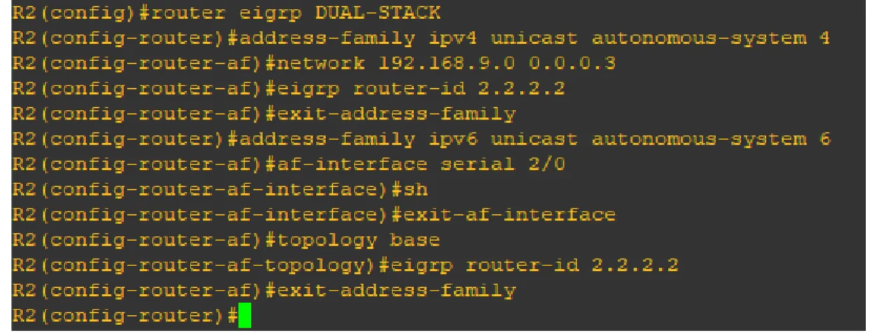
R2
router eigrp DUAL-STACK
address-family ipv4 unicast autonomous-system 4 network 192.168.9.0 0.0.0.3
19
exit-address-family
address-family ipv6 unicast autonomous-system 6 af-interface serial 2/0
sh
exit-af-interface topology base
eigrp router-id 2.2.2.2 exit-address-family
Figura 14 Configuración aplicada en R2
9. Configurar las interfaces pasivas para EIGRP según sea apropiado.
En R2, configurar la redistribución mutua entre OSPF y EIGRP para IPv4 e IPv6. Asignar métricas apropiadas cuando sea necesario.
R1
router eigrp 10
passive-interface Et0/0
Figura 15 Configuración EIGRP en R1 se Replica en R2, R3
R2
router eigrp 10
20
Figura 16 Configuración aplicada en R2
R3
router eigrp 10
passive-interface Et0/0
Figura 17 Configuración aplicada en R3
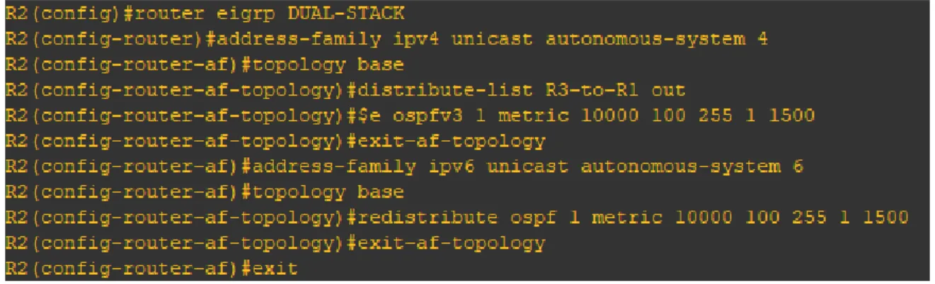
10. En R2, configurar la redistribución mutua entre OSPF y EIGRP para IPv4 e IPv6. Asignar métricas apropiadas cuando sea necesario.
R2
router eigrp DUAL-STACK
address-family ipv4 unicast autonomous-system 4 topology base
distribute-list R3-to-R1 out
redistribute ospfv3 1 metric 10000 100 255 1 1500 exit-af-topology
address-family ipv6 unicast autonomous-system 6 topology base
redistribute ospf 1 metric 10000 100 255 1 1500 exit-af-topology
21
Figura 18 Configuración aplicada en R2
11. En R2, de hacer publicidad de la ruta 192.168.3.0/24 a R1 mediante una lista de distribución y ACL.
R2
ip access-list standard R3-to-R1 remark ACL to filter 192.168.3.0/24 deny 192.168.3.0 0.0.0.255
permit any
Figura 19 Configuración aplicada en R2
Parte 2: Pruebe la conectividad de red y el control de ruta.
a. Registrar las tablas de enrutamiento en cada uno de los routers, acorde con los parámetros de configuración establecidos en el escenario propuesto.
22
Figura 20 Verificación de los protocolos
Figura 21 Verificación de los protocolos
23
Figura 22 Verificación de los protocolos
24
Figura 24 Mostrando los vecinos conectados
25
Figura 25 Verificación de los protocolos de enrutamiento
26
Figura 27 verificación de protocolo de enrutamiento vecino
b. Verificar comunicación entre routers mediante el comando ping y traceroute.
R1
27
28
R2
Figura 30 continuacion fig. 30
29
30
R3
31
c. Verificar que las rutas filtradas no están presentes en las tablas de enrutamiento de los routers correctas.
R1
32
33
R2
34
35
36
37
R3
38
39
Figura 41 continuacion de figura 42
40
DESARROLLO
Escenario 2
Una empresa de comunicaciones presenta una estructura Core acorde a la topología de red, en donde el estudiante será el administrador de la red, el cual deberá configurar e interconectar entre sí cada uno de los dispositivos que forman parte del escenario, acorde con los lineamientos establecidos para el direccionamiento IP, etherchannels, VLANs y demás aspectos que forman parte del escenario propuesto.
Topología de red
41 Figura 1 Escenario 2
Introducción al Escenario 2
Este escenario basado en habilidades (SBA) es el desempeño práctico final para la formación de la Academia para el curso CCNPv7 SWITCH.
En la Parte 1, se crea la red física. En la parte 2, usted configura diversas características tales como trunking, EtherChannel, VTP, VLANs, SVI, links ruteados, y HSRP. En la Parte 3, usted crea un script Tcl para probar la Conectividad IP y utiliza los comandos show para verificar las opciones configuradas. Este escenario combina la configuración del dispositivo y la solución de problemas.
Objetivos
Parte 1: Construir la topología de red física.
Parte 2: Configurar los switches en la topología de acuerdo con el diagrama y las especificaciones proporcionadas.
42
Tabla 2 tablas de direccionamiento de cada dispositivo y sus respectivas interfaces
Parte 1: Configurar la red de acuerdo con las especificaciones.
a. Apagar todas las interfaces en cada switch.
DLS1#en (para ingresar a modo privilegiado)
DLS1#conf t (para ingresar al modo de configuración global)
DLS1(config)#int range Et0/0-3,Et1/0-2 (ingresamos al rango de interfaces a configurar)
DLS1(config-if-range)#shutdown (apagamos las interfaces según el escenario)
DLS1(config-if-range)#
Figura 42 Apagar rango de interfaces
DLS2#conf t
DLS2(config)#int range Et0/0-3,Et1/0-2 DLS2(config-if-range)#shutdown
43
ALS1#conf t
ALS1(config)#int range Et0/0-3,Et1/0-2 ALS1(config-if-range)#shutdown
Figura 44 Configuración aplicada en ALS1
ALS2#conf t
ALS2(config)#int range Et0/0-3,Et1/0-2 ALS2(config-if-range)#shutdown
Figura 45 Configuración aplicada en ALS2
b. Asignar un nombre a cada switch acorde al escenario establecido.
DLS1(config)#hostname DLS1
DLS2(config)#hostname DLS2
ALS1(config)#hostname ALS1
AlS2(config)#hostname ALS2
c. Configurar los puertos troncales y Port-channels tal como se muestra en el diagrama.
1) La conexión entre DLS1 y DLS2 será un EtherChannel capa-3 utilizando LACP. Para DLS1 se utilizará la dirección IP 10.12.12.1/30 y para DLS2 utilizará 10.12.12.2/30.
DLS1(config)#int range Et1/0-1 DLS1(config-if-range)#no switchport
DLS1(config-if-range)#channel-group 12 mode active DLS1(config-if-range)#no shutdown
44
Figura 46 de acuerdo al escenario creamos EtherChannel en los puertos
DLS1(config)#int range Et0/0-1 DLS1(config-if-range)#no switchport
DLS1(config-if-range)#channel-group 1 mode active DLS1(config-if-range)#no shutdown
Figura 47 de acuerdo al escenario creamos EtherChannel en los puertos
DLS1(config)#int range Et0/2-3 DLS1(config-if-range)#no switchport
DLS1(config-if-range)#channel-group 4 mode desirable DLS1(config-if-range)#no shut
45
DLS2(config)#int range Et1/0-1 DLS2(config-if-range)#no switchport
DLS2(config-if-range)#channel-group 12 mode active DLS2(config-if-range)#no shut
Figura 49 de acuerdo al escenario creamos EtherChannel en los puertos
DLS2(config)#int range Et0/0-1 DLS2(config-if-range)#no switchport
DLS2(config-if-range)#channel-group 2 mode active DLS2(config-if-range)#no sh
46
DLS2(config)#int range Et0/2-3 DLS2(config-if-range)#no switchport
DLS2(config-if-range)#channel-group 3 mode desirable DLS2(config-if-range)#no shutdown
Figura 51 de acuerdo al escenario creamos EtherChannel activo en los puertos
ALS1(config)#int range Et0/0-1 ALS1(config-if-range)#no switchport
ALS1(config-if-range)#channel-group 1 mode active ALS1(config-if-range)#no shtutdown
Figura 52 de acuerdo al escenario creamos EtherChannel en negociación en los puertos
ALS1(config)#int range Et0/2-3 ALS1(config-if-range)#no switchport
47
Figura 53 de acuerdo al escenario creamos EtherChannel activo en los puertos
ALS2(config)#int range Et0/2-3 ALS2(config-if-range)#no switchport
ALS2(config-if-range)#channel-group 4 mode desirable ALS2(config-if-range)#no shut
48
ALS2(config-if-range)#int range Et0/0-1 ALS2(config-if-range)#no switchport
ALS2(config-if-range)#channel-group 2 mode active ALS2(config-if-range)#no shutdown
Figura 55 de acuerdo al escenario creamos EtherChannel en negociación en los puertos
DLS1(config)#int port-channel 12
DLS1(config-if)#ip address 10.12.12.1 255.255.255.252
Figura 56 asignación de ip al puerto po 12
DLS2(config)#int port-channel 12
DLS2(config-if)#ip address 10.12.12.2 255.255.255.252
49
2) Los Port-channels en las interfaces Fa0/7 y Fa0/8 utilizarán LACP.
DLS1(config-if)#int range Et0/0-1 DLS1(config-if-range)#no switchport
DLS1(config-if-range)#channel-group 1 mode active DLS1(config-if-range)#no shutdown
Figura 58 configuración del rango de puertos como LACP
ALS1(config)#int range Et0/0-1 ALS1(config-if-range)#no switchport
ALS1(config-if-range)#channel-group 1 mode active ALS1(config-if-range)#no shtutdown
Figura 59 configuración del rango de puertos como LACP
DLS2(config)#int range Et0/0-1
DLS2(config-if-range)#channel-group 2 mode active DLS2(config-if-range)#no shut
50
ALS2(config-if-range)#int range Et0/0-1
ALS2(config-if-range)#channel-group 2 mode active ALS2(config-if-range)#no shutdown
Figura 61 configuración del rango de puertos como LACP
3) Los Port-channels en las interfaces F0/9 y fa0/10 utilizará PAgP.
DLS1(config)#int range Et0/2-3
DLS1(config-if-range)#channel-group 4 mode desirable DLS1(config-if-range)#no shut
Figura 62 configuración del rango de puertos como PAgP
DLS2(config)#int range Et0/2-3
DLS2(config-if-range)#channel-group 3 mode desirable DLS2(config-if-range)#no shutdown
Figura 63 configuración del rango de puertos como PAgP
ALS1(config)#int range Et0/2-3
ALS1(config-if-range)#channel-group 3 mode desirable ALS1(config-if-range)#no shut
51
ALS2(config)#int range Et0/2-3
ALS2(config-if-range)#channel-group 4 mode desirable ALS2(config-if-range)#no shutdown
Figura 65 configuración del rango de puertos como PAgP
4) Todos los puertos troncales serán asignados a la VLAN 800 como la VLAN nativa.
DLS1(config)#int range Et0/0-3
DLS1(config-if-range)#switchport trunk encapsulation dot1q DLS1(config-if-range)#switchport trunk native vlan 800 DLS1(config-if-range)#switchport mode trunk
DLS1(config-if-range)#switchport nonegotiate DLS1(config-if-range)#no shutdown
52
DLS2(config)#int range Et0/0-3
DLS2(config-if-range)#switchport trunk encapsulation dot1q DLS2(config-if-range)#switchport trunk native vlan 800 DLS2(config-if-range)#switchport mode trunk
DLS2(config-if-range)#switchport nonegotiate DLS2(config-if-range)#no shutdown
Figura 67 asignación de puertos a la vlan 800
ALS1(config)#int range Et0/0-3
ALS1(config-if-range)#switchport trunk encapsulation dot1q ALS1(config-if-range)#switchport trunk native vlan 800 ALS1(config-if-range)#switchport mode trunk
ALS1(config-if-range)#switchport nonegotiate ALS1(config-if-range)#no shutdown
53
ALS2(config)#int range Et0/0-3
ALS2(config-if-range)#switchport trunk encapsulation dot1q ALS2(config-if-range)#switchport trunk native vlan 800 ALS2(config-if-range)#switchport mode trunk
ALS2(config-if-range)#switchport nonegotiate ALS2(config-if-range)#no shutdown
Figura 69 asignación de puertos a la vlan 800
d. Configurar DLS1, ALS1, y ALS2 para utilizar VTP versión 3
DLS1(config)#vtp domain UNAD DLS1(config)#vtp version 3
DLS1(config)#vtp password cisco123
Figura 70 activación de vtp versión 3
ALS1(config)#vtp domain UNAD ALS1(config)#vtp version 3
ALS1(config)#vtp password cisco123
54
ALS2(config)#vtp domain UNAD ALS2(config)#vtp version 3
ALS2(config)#vtp password cisco123
Figura 72 Figura 72 activación de vtp versión 3
2) Configurar DLS1 como servidor principal para las VLAN.
DLS1#vtp primary vlan
Figura 73 configuración DLS 1 como servidor para las vlan
3) Configurar ALS1 y ALS2 como clientes VTP.
ALS1(config)#vtp mode client
Figura 74 configuración de como vtp cliente
ALS2(config)#vtp mode client
55
e. Configurar en el servidor principal las siguientes VLAN:
Tabla 3 Vlan a crear con sus nombres
56
Figura 76 creación de vlan´s según tabla 2
f. En DLS1, suspender la VLAN 434.
DLS1(config)#vlan 434
DLS1(config-vlan)#name ESTACIONAMIENTO DLS1(config-vlan)#state suspend
57
g. Configurar DLS2 en modo VTP transparente VTP utilizando VTP versión 2, y configurar en DLS2 las mismas VLAN que en DLS1.
DLS2(config)#vtp version 2
DLS2(config)#vtp mode transparent
58
h. Suspender VLAN 434 en DLS2.
DLS2(config)#vlan 434
DLS2(config-vlan)#name ESTACIONAMIENTO DLS2(config-vlan)#state suspend
Figura 79 colocar la vlan 434 como suspend
i. En DLS2, crear VLAN 567 con el nombre de CONTABILIDAD. La VLAN de CONTABILIDAD no podrá estar disponible en cualquier otro Switch de la red.
DLS2(config)#vlan 567
DLS2(config-vlan)#name CONTABILIDAD DLS2(config-vlan)#exit
Figura 80 creación de la vlan 534 en DLS 2
j. Configurar DLS1 como Spanning tree root para las VLAN 1, 12, 434, 800, 1010, 1111 y 3456 y como raíz secundaria para las VLAN 123 y 234.
DLS1(config)#spanning-tree vlan 1,12,434,800,1010,1111,3456 root primary DLS1(config)#spanning-tree vlan 123,234 root secondary
59
k. Configurar DLS2 como Spanning tree root para las VLAN 123 y 234 y como una raíz secundaria para las VLAN 12, 434, 800, 1010, 1111 y 3456.
DLS2(config)#spanning-tree vlan 123,234 root primary
DLS2(config)#spanning-tree vlan 1,12,434,800,1010,1111,3456 root secondary
Figura 82 creación Spanning tree root
l. Configurar todos los puertos como troncales de tal forma que solamente las VLAN que se han creado se les permitirá circular a través de éstos puertos.
DLS1(config)#int range Et0/0-3
DLS1(config-if-range)#switchport trunk allowed vlan 12,123,234,800,1010,1111,3456
Figura 83 configurar los puertos como troncal
DLS2(config)#int range Et0/0-3
DLS2(config-if-range)# switchport trunk allowed vlan 12,123,234,800,1010,1111,3456
Figura 84 configurar los puertos como troncal
ALS1(config)#int range Et0/0-3
ALS1(config-if-range)# switchport trunk allowed vlan 12,123,234,800,1010,1111,3456
60
ALS2(config)#int range Et0/0-3
ALS2(config-if-range)# switchport trunk allowed vlan 12,123,234,800,1010,1111,3456
Figura 86 configurar los puertos como troncal
m. Configurar las siguientes interfaces como puertos de acceso, asignados a las VLAN de la siguiente manera:
DLS1(config)#int Et1/2
DLS1(config-if)#switchport host
DLS1(config-if)#switchport mode access DLS1(config-if)#switchport access vlan 3456 DLS1(config-if)#no shutdown
61
DLS1(config-if)#int Et1/3
DLS1(config-if)#switchport host
DLS1(config-if)#switchport mode access DLS1(config-if)#switchport access vlan 1111 DLS1(config-if)#no shutdown
Figura 88 configurar las interfaces como puerto de acceso
DLS2(config)#int Et1/2
DLS2(config-if)#switchport mode access DLS2(config-if)#switchport access vlan 12 DLS2(config-if)#switchport host
DLS2(config-if)#no shut DLS2(config-if)#int Et1/2
DLS2(config-if)#switchport host
DLS2(config-if)#switchport mode access DLS2(config-if)#switchport access vlan 1010 DLS2(config-if)#no shutdown
DLS2(config-if)#int Et1/3
DLS2(config-if)#switchport host
DLS2(config-if)#switchport mode access DLS2(config-if)#switchport access vlan 1111 DLS2(config-if)#no shutdown
DLS2(config-if)#int range Et2/1-2 DLS2(config-if-range)#switchport host
62
Figura 89 configurar las interfaces como puerto de acceso
ALS1(config)#int Et1/2
ALS1(config-if)#switchport host
ALS1(config-if)#switchport mode access ALS1(config-if)#switchport access vlan 123 ALS1(config-if)#switchport access vlan 1010 ALS1(config-if)#no shutdown
ALS1(config-if)#int Et1/3
ALS1(config-if)#switchport host
63
Figura 90 configurar las interfaces como puerto de acceso
ALS2(config)#int Et1/2
ALS2(config-if)#switchport host
ALS2(config-if)#switchport mode access ALS2(config-if)#switchport access vlan 234 ALS2(config-if)#no shutdown
ALS2(config-if)#int Et1/3
ALS2(config-if)#switchport host
64
65
Part 2: conectividad de red de prueba y las opciones configuradas.
a. Verificar la existencia de las VLAN correctas en todos los switches y la asignación de puertos troncales y de acceso.
Figura 92 verificación de la configuración aplicada
66
Figura 94 verificación de la configuración aplicada
67
Anexo de script de configuración aplicada a los dispositivos DLS1.
DLS1 configuracion.
spanning-tree mode pvst
spanning-tree extend system-id
spanning-tree vlan 1,12,434,800,1010,1111,3456 priority 24576 spanning-tree vlan 123,234 priority 28672
!
vlan internal allocation policy ascending !
ip tcp synwait-time 5 !
interface Port-channel12 no switchport
ip address 10.12.12.1 255.255.255.252 !
interface Port-channel1 no switchport
no ip address !
interface Port-channel4 no switchport
no ip address !
interface Ethernet0/0
switchport trunk allowed vlan 12,123,234,800,1010,1111,3456 switchport trunk encapsulation dot1q
switchport trunk native vlan 800 switchport nonegotiate
switchport mode trunk duplex auto
!
interface Ethernet0/1
switchport trunk allowed vlan 12,123,234,800,1010,1111,3456 switchport trunk encapsulation dot1q
switchport trunk native vlan 800 switchport nonegotiate
switchport mode trunk duplex auto
!
interface Ethernet0/2
switchport trunk allowed vlan 12,123,234,800,1010,1111,3456 switchport trunk encapsulation dot1q
68
switchport nonegotiate switchport mode trunk duplex auto
!
interface Ethernet0/3
switchport trunk allowed vlan 12,123,234,800,1010,1111,3456 switchport trunk encapsulation dot1q
switchport trunk native vlan 800 switchport nonegotiate
switchport mode trunk duplex auto
!
interface Ethernet1/0 no switchport
no ip address duplex auto
channel-group 12 mode active !
interface Ethernet1/1 no switchport
no ip address duplex auto
channel-group 12 mode active !
interface Ethernet1/2
switchport access vlan 3456 switchport mode access spanning-tree portfast !
interface Ethernet1/3
switchport access vlan 1111 switchport mode access spanning-tree portfast
DLS2 configuracion.
vtp domain UNAD vtp mode transparent
no ip icmp rate-limit unreachable !
no ip domain-lookup ip cef
no ipv6 cef !
69
spanning-tree extend system-id
spanning-tree vlan 1,12,434,800,1010,1111,3456 priority 28672 spanning-tree vlan 123,234 priority 24576
!
vlan internal allocation policy ascending ! vlan 12 name EJECUTIVOS ! vlan 123 name MANTENIMIENTO ! vlan 234 name HUESPEDES ! vlan 434 name ESTACIONAMIENTO state suspend ! vlan 567 name CONTABILIDAD ! vlan 800 name NATIVA ! vlan 1010 name VOZ ! vlan 1111 name VIDEONET ! vlan 3456 name ADMINISTRACION !
ip tcp synwait-time 5 !
interface Port-channel3 no switchport
no ip address !
interface Port-channel2 no switchport
no ip address !
70
no switchport
ip address 10.12.12.2 255.255.255.252 !
interface Ethernet0/0
switchport trunk allowed vlan 12,123,234,800,1010,1111,3456 switchport trunk encapsulation dot1q
switchport trunk native vlan 800 switchport nonegotiate
switchport mode trunk duplex auto
!
interface Ethernet0/1
switchport trunk allowed vlan 12,123,234,800,1010,1111,3456 switchport trunk encapsulation dot1q
switchport trunk native vlan 800 switchport nonegotiate
switchport mode trunk duplex auto
!
interface Ethernet0/2
switchport trunk allowed vlan 12,123,234,800,1010,1111,3456 switchport trunk encapsulation dot1q
switchport trunk native vlan 800 switchport nonegotiate
switchport mode trunk duplex auto
!
interface Ethernet0/3
switchport trunk allowed vlan 12,123,234,800,1010,1111,3456 switchport trunk encapsulation dot1q
switchport trunk native vlan 800 switchport nonegotiate
switchport mode trunk duplex auto
!
interface Ethernet1/0 no switchport
no ip address duplex auto
channel-group 12 mode active !
interface Ethernet1/1 no switchport
71
channel-group 12 mode active !
interface Ethernet1/2
switchport access vlan 1010 switchport mode access spanning-tree portfast !
interface Ethernet1/3
switchport access vlan 1111 switchport mode access spanning-tree portfast !
interface Ethernet2/0 !
interface Ethernet2/1
switchport access vlan 567 switchport mode access spanning-tree portfast !
interface Ethernet2/2
switchport access vlan 567 switchport mode access spanning-tree portfast
ALS 1 configuracion
interface Port-channel3 no switchport
no ip address !
interface Port-channel1 no switchport
no ip address !
interface Ethernet0/0
switchport trunk allowed vlan 12,123,234,800,1010,1111,3456 switchport trunk encapsulation dot1q
switchport trunk native vlan 800 switchport nonegotiate
switchport mode trunk duplex auto
!
interface Ethernet0/1
72
switchport trunk native vlan 800 switchport nonegotiate
switchport mode trunk duplex auto
!
interface Ethernet0/2
switchport trunk allowed vlan 12,123,234,800,1010,1111,3456 switchport trunk encapsulation dot1q
switchport trunk native vlan 800 switchport nonegotiate
switchport mode trunk duplex auto
!
interface Ethernet0/3
switchport trunk allowed vlan 12,123,234,800,1010,1111,3456 switchport trunk encapsulation dot1q
switchport trunk native vlan 800 switchport nonegotiate
switchport mode trunk duplex auto ! interface Ethernet1/0 shutdown ! interface Ethernet1/1 shutdown ! interface Ethernet1/2
switchport access vlan 1010 switchport mode access spanning-tree portfast !
interface Ethernet1/3
switchport access vlan 1111 switchport mode access spanning-tree portfast ALS 2 configuracion.
interface Port-channel2 no switchport
no ip address !
interface Port-channel4 no switchport
73
!
interface Ethernet0/0
switchport trunk allowed vlan 12,123,234,800,1010,1111,3456 switchport trunk encapsulation dot1q
switchport trunk native vlan 800 switchport nonegotiate
switchport mode trunk duplex auto
!
interface Ethernet0/1
switchport trunk allowed vlan 12,123,234,800,1010,1111,3456 switchport trunk encapsulation dot1q
switchport trunk native vlan 800 switchport nonegotiate
switchport mode trunk duplex auto
!
interface Ethernet0/2
switchport trunk allowed vlan 12,123,234,800,1010,1111,3456 switchport trunk encapsulation dot1q
switchport trunk native vlan 800 switchport nonegotiate
switchport mode trunk duplex auto
!
interface Ethernet0/3
switchport trunk allowed vlan 12,123,234,800,1010,1111,3456 switchport trunk encapsulation dot1q
switchport trunk native vlan 800 switchport nonegotiate
switchport mode trunk duplex auto ! interface Ethernet1/0 shutdown ! interface Ethernet1/1 shutdown ! interface Ethernet1/2
switchport access vlan 234 switchport mode access spanning-tree portfast !
74
switchport access vlan 1111 switchport mode access spanning-tree portfast !
interface Ethernet2/0 !
interface Ethernet2/1 !
interface Ethernet2/2 !
interface Ethernet2/3 !
interface Ethernet3/0 !
interface Ethernet3/1 !
interface Ethernet3/2 !
interface Ethernet3/3 !
75
b. Verificar que el EtherChannel entre DLS1 y ALS1 está configurado correctamente
Figura 96 verificación de la configuración aplicada
76
c. Verificar la configuración de Spanning tree entre DLS1 o DLS2 para cada VLAN.
DLS1#show spanning-tree
VLAN0001
Spanning tree enabled protocol ieee Root ID Priority 24577
Address aabb.cc00.0100 This bridge is the root
Hello Time 2 sec Max Age 20 sec Forward Delay 15 sec
Bridge ID Priority 24577 (priority 24576 sys-id-ext 1) Address aabb.cc00.0100
Hello Time 2 sec Max Age 20 sec Forward Delay 15 sec Aging Time 300 sec
Interface Role Sts Cost Prio.Nbr Type
--- ---- --- --- --- --- Et2/0 Desg FWD 100 128.9 Shr
Et2/1 Desg FWD 100 128.10 Shr Et2/2 Desg FWD 100 128.11 Shr Et2/3 Desg FWD 100 128.12 Shr Et3/0 Desg FWD 100 128.13 Shr Et3/1 Desg FWD 100 128.14 Shr Et3/2 Desg FWD 100 128.15 Shr Et3/3 Desg FWD 100 128.16 Shr
VLAN0012
Spanning tree enabled protocol ieee Root ID Priority 24588
Address aabb.cc00.0100 This bridge is the root
Hello Time 2 sec Max Age 20 sec Forward Delay 15 sec
Bridge ID Priority 24588 (priority 24576 sys-id-ext 12) Address aabb.cc00.0100
Hello Time 2 sec Max Age 20 sec Forward Delay 15 sec Aging Time 300 sec
Interface Role Sts Cost Prio.Nbr Type
--- ---- --- --- --- --- Et0/2 Desg FWD 100 128.3 Shr
77
VLAN0123
Spanning tree enabled protocol ieee Root ID Priority 24699
Address aabb.cc00.0200 Cost 200
Port 3 (Ethernet0/2)
Hello Time 2 sec Max Age 20 sec Forward Delay 15 sec
Bridge ID Priority 28795 (priority 28672 sys-id-ext 123) Address aabb.cc00.0100
Hello Time 2 sec Max Age 20 sec Forward Delay 15 sec Aging Time 300 sec
Interface Role Sts Cost Prio.Nbr Type
--- ---- --- --- --- --- Et0/2 Root FWD 100 128.3 Shr
Et0/3 Altn BLK 100 128.4 Shr
VLAN0234
Spanning tree enabled protocol ieee Root ID Priority 24810
Address aabb.cc00.0200 Cost 200
Port 3 (Ethernet0/2)
Hello Time 2 sec Max Age 20 sec Forward Delay 15 sec
Bridge ID Priority 28906 (priority 28672 sys-id-ext 234) Address aabb.cc00.0100
Hello Time 2 sec Max Age 20 sec Forward Delay 15 sec Aging Time 300 sec
Interface Role Sts Cost Prio.Nbr Type
--- ---- --- --- --- --- Et0/2 Root FWD 100 128.3 Shr
Et0/3 Altn BLK 100 128.4 Shr
VLAN0800
Spanning tree enabled protocol ieee Root ID Priority 25376
Address aabb.cc00.0100 This bridge is the root
Hello Time 2 sec Max Age 20 sec Forward Delay 15 sec
78
Hello Time 2 sec Max Age 20 sec Forward Delay 15 sec Aging Time 300 sec
Interface Role Sts Cost Prio.Nbr Type
--- ---- --- --- --- --- Et0/2 Desg FWD 100 128.3 Shr
Et0/3 Desg FWD 100 128.4 Shr
VLAN1010
Spanning tree enabled protocol ieee Root ID Priority 25586
Address aabb.cc00.0100 This bridge is the root
Hello Time 2 sec Max Age 20 sec Forward Delay 15 sec
Bridge ID Priority 25586 (priority 24576 sys-id-ext 1010) Address aabb.cc00.0100
Hello Time 2 sec Max Age 20 sec Forward Delay 15 sec Aging Time 300 sec
Interface Role Sts Cost Prio.Nbr Type
--- ---- --- --- --- --- Et0/2 Desg FWD 100 128.3 Shr
Et0/3 Desg FWD 100 128.4 Shr
VLAN1111
Spanning tree enabled protocol ieee Root ID Priority 25687
Address aabb.cc00.0100 This bridge is the root
Hello Time 2 sec Max Age 20 sec Forward Delay 15 sec
Bridge ID Priority 25687 (priority 24576 sys-id-ext 1111) Address aabb.cc00.0100
Hello Time 2 sec Max Age 20 sec Forward Delay 15 sec Aging Time 300 sec
Interface Role Sts Cost Prio.Nbr Type
--- ---- --- --- --- --- Et0/2 Desg FWD 100 128.3 Shr
79
VLAN3456
Spanning tree enabled protocol ieee Root ID Priority 28032
Address aabb.cc00.0100 This bridge is the root
Hello Time 2 sec Max Age 20 sec Forward Delay 15 sec
Bridge ID Priority 28032 (priority 24576 sys-id-ext 3456) Address aabb.cc00.0100
Hello Time 2 sec Max Age 20 sec Forward Delay 15 sec Aging Time 300 sec
Interface Role Sts Cost Prio.Nbr Type
--- ---- --- --- --- --- Et0/2 Desg FWD 100 128.3 Shr
Et0/3 Desg FWD 100 128.4 Shr Et1/2 Desg FWD 100 128.7 Shr Edge
DLS2#show spanning-tree
VLAN0001
Spanning tree enabled protocol ieee Root ID Priority 28673
Address aabb.cc00.0200 This bridge is the root
Hello Time 2 sec Max Age 20 sec Forward Delay 15 sec
Bridge ID Priority 28673 (priority 28672 sys-id-ext 1) Address aabb.cc00.0200
Hello Time 2 sec Max Age 20 sec Forward Delay 15 sec Aging Time 300 sec
Interface Role Sts Cost Prio.Nbr Type
--- ---- --- --- --- --- Et2/0 Desg FWD 100 128.9 Shr
Et2/3 Desg FWD 100 128.12 Shr Et3/0 Desg FWD 100 128.13 Shr Et3/1 Desg FWD 100 128.14 Shr Et3/2 Desg FWD 100 128.15 Shr Et3/3 Desg FWD 100 128.16 Shr
VLAN0012
Spanning tree enabled protocol ieee Root ID Priority 24588
80
Cost 200
Port 1 (Ethernet0/0)
Hello Time 2 sec Max Age 20 sec Forward Delay 15 sec
Bridge ID Priority 28684 (priority 28672 sys-id-ext 12) Address aabb.cc00.0200
Hello Time 2 sec Max Age 20 sec Forward Delay 15 sec Aging Time 300 sec
Interface Role Sts Cost Prio.Nbr Type
--- ---- --- --- --- --- Et0/0 Root FWD 100 128.1 Shr
Et0/1 Altn BLK 100 128.2 Shr Et0/2 Desg FWD 100 128.3 Shr Et0/3 Desg FWD 100 128.4 Shr
VLAN0123
Spanning tree enabled protocol ieee Root ID Priority 24699
Address aabb.cc00.0200 This bridge is the root
Hello Time 2 sec Max Age 20 sec Forward Delay 15 sec
Bridge ID Priority 24699 (priority 24576 sys-id-ext 123) Address aabb.cc00.0200
Hello Time 2 sec Max Age 20 sec Forward Delay 15 sec Aging Time 300 sec
Interface Role Sts Cost Prio.Nbr Type
--- ---- --- --- --- --- Et0/0 Desg FWD 100 128.1 Shr
Et0/1 Desg FWD 100 128.2 Shr Et0/2 Desg FWD 100 128.3 Shr Et0/3 Desg FWD 100 128.4 Shr
VLAN0234
Spanning tree enabled protocol ieee Root ID Priority 24810
Address aabb.cc00.0200 This bridge is the root
Hello Time 2 sec Max Age 20 sec Forward Delay 15 sec
Bridge ID Priority 24810 (priority 24576 sys-id-ext 234) Address aabb.cc00.0200
81
Aging Time 300 sec
Interface Role Sts Cost Prio.Nbr Type
--- ---- --- --- --- --- Et0/0 Desg FWD 100 128.1 Shr
Et0/1 Desg FWD 100 128.2 Shr Et0/2 Desg FWD 100 128.3 Shr Et0/3 Desg FWD 100 128.4 Shr
VLAN0567
Spanning tree enabled protocol ieee Root ID Priority 33335
Address aabb.cc00.0200 This bridge is the root
Hello Time 2 sec Max Age 20 sec Forward Delay 15 sec
Bridge ID Priority 33335 (priority 32768 sys-id-ext 567) Address aabb.cc00.0200
Hello Time 2 sec Max Age 20 sec Forward Delay 15 sec Aging Time 300 sec
Interface Role Sts Cost Prio.Nbr Type
--- ---- --- --- --- --- Et2/1 Desg FWD 100 128.10 Shr Edge
Et2/2 Desg FWD 100 128.11 Shr Edge
VLAN0800
Spanning tree enabled protocol ieee Root ID Priority 25376
Address aabb.cc00.0100 Cost 200
Port 1 (Ethernet0/0)
Hello Time 2 sec Max Age 20 sec Forward Delay 15 sec
Bridge ID Priority 29472 (priority 28672 sys-id-ext 800) Address aabb.cc00.0200
Hello Time 2 sec Max Age 20 sec Forward Delay 15 sec Aging Time 300 sec
Interface Role Sts Cost Prio.Nbr Type
--- ---- --- --- --- --- Et0/0 Root FWD 100 128.1 Shr
82
VLAN1010
Spanning tree enabled protocol ieee Root ID Priority 25586
Address aabb.cc00.0100 Cost 200
Port 1 (Ethernet0/0)
Hello Time 2 sec Max Age 20 sec Forward Delay 15 sec
Bridge ID Priority 29682 (priority 28672 sys-id-ext 1010) Address aabb.cc00.0200
Hello Time 2 sec Max Age 20 sec Forward Delay 15 sec Aging Time 300 sec
Interface Role Sts Cost Prio.Nbr Type
--- ---- --- --- --- --- Et0/0 Root FWD 100 128.1 Shr
Et0/1 Altn BLK 100 128.2 Shr Et0/2 Desg FWD 100 128.3 Shr Et0/3 Desg FWD 100 128.4 Shr Et1/2 Desg FWD 100 128.7 Shr Edge
VLAN1111
Spanning tree enabled protocol ieee Root ID Priority 25687
Address aabb.cc00.0100 Cost 200
Port 1 (Ethernet0/0)
Hello Time 2 sec Max Age 20 sec Forward Delay 15 sec
Bridge ID Priority 29783 (priority 28672 sys-id-ext 1111) Address aabb.cc00.0200
Hello Time 2 sec Max Age 20 sec Forward Delay 15 sec Aging Time 300 sec
Interface Role Sts Cost Prio.Nbr Type
--- ---- --- --- --- --- Et0/0 Root FWD 100 128.1 Shr
83
VLAN3456
Spanning tree enabled protocol ieee Root ID Priority 28032
Address aabb.cc00.0100 Cost 200
Port 1 (Ethernet0/0)
Hello Time 2 sec Max Age 20 sec Forward Delay 15 sec
Bridge ID Priority 32128 (priority 28672 sys-id-ext 3456) Address aabb.cc00.0200
Hello Time 2 sec Max Age 20 sec Forward Delay 15 sec Aging Time 300 sec
Interface Role Sts Cost Prio.Nbr Type
--- ---- --- --- --- --- Et0/0 Root FWD 100 128.1 Shr
84
CONCLUSIONES
En la ejecución del trabajo final practico tipo de prueba de habilidades CCNP se pudieron aplicar en gran escala cada una de las de las destrezas y conocimientos que se obtuvieron a lo largo del diplomado, aplicándolas en los escenarios propuestos buscando siempre un entorno acorde al estándar de la industria basado en casos.
Se realizaron las configuraciones a la medida de cada uno de los ejercicios, estableciendo los protocolos de enrutamiento a gran escala y direccionamiento de IP tanto en ipv4 como en ipv6, por los que se adquirieron grandes destrezas en los manejos de dispositivos como routers y switches, con sus respectivos servicios.
Demostrando así que se pudieron dar soluciones a las dificultades que se obtuvieron en el desarrollo de la prueba de habilidades prácticas y un excelente manejo del programa de GNS3 , y el SmartLabs.
Todos los protocolos de enrutamiento tienen el mismo propósito: conocer sobre redes remotas y adaptarse rápidamente cuando ocurre un cambio en la topología. El método que usa un protocolo de enrutamiento para lograr su propósito depende del algoritmo que use y de las características operativas de ese protocolo. Las operaciones de un protocolo de enrutamiento dinámico varían según el tipo de protocolo de enrutamiento y el protocolo de enrutamiento en sí.
85
BIBLIOGRÁFIA
Teare, D., Vachon B., Graziani, R. (2015). CISCO Press (Ed). Basic Network and Routing Concepts. Implementing Cisco IP Routing (ROUTE) Foundation Learning
Guide CCNP ROUTE 300-101. Recuperado de
https://1drv.ms/b/s!AmIJYei-NT1IlnMfy2rhPZHwEoWx
Teare, D., Vachon B., Graziani, R. (2015). CISCO Press (Ed). EIGRP Implementation. Implementing Cisco IP Routing (ROUTE) Foundation Learning
Guide CCNP ROUTE 300-101. Recuperado de
https://1drv.ms/b/s!AmIJYei-NT1IlnMfy2rhPZHwEoWx
Teare, D., Vachon B., Graziani, R. (2015). CISCO Press (Ed). OSPF Implementation. Implementing Cisco IP Routing (ROUTE) Foundation Learning
Guide CCNP ROUTE 300-101. Recuperado de
https://1drv.ms/b/s!AmIJYei-NT1IlnMfy2rhPZHwEoWx
Teare, D., Vachon B., Graziani, R. (2015). CISCO Press (Ed). Manipulating Routing Updates. Implementing Cisco IP Routing (ROUTE) Foundation Learning Guide
CCNP ROUTE 300-101. Recuperado de https://1drv.ms/b/s!AmIJYei-
Froom, R., Frahim, E. (2015). CISCO Press (Ed). Spanning Tree Implementation. Implementing Cisco IP Switched Networks (SWITCH) Foundation Learning Guide
CCNP SWITCH 300-115. Recuperado de
https://1drv.ms/b/s!AmIJYei-NT1IlnWR0hoMxgBNv1CJ
Froom, R., Frahim, E. (2015). CISCO Press (Ed). InterVLAN Routing. Implementing Cisco IP Switched Networks (SWITCH) Foundation Learning Guide CCNP SWITCH
300-115. Recuperado de https://1drv.ms/b/s!AmIJYei-NT1IlnWR0hoMxgBNv1CJ
Froom, R., Frahim, E. (2015). CISCO Press (Ed). Fundamentals Review. Implementing Cisco IP Switched Networks (SWITCH) Foundation Learning Guide
CCNP SWITCH 300-115. Recuperado de
https://1drv.ms/b/s!AmIJYei-NT1IlnWR0hoMxgBNv1CJ
Froom, R., Frahim, E. (2015). CISCO Press (Ed). Campus Network Architecture. Implementing Cisco IP Switched Networks (SWITCH) Foundation Learning Guide
56CCNP SWITCH 300-115. Recuperado de
https://1drv.ms/b/s!AmIJYei-NT1IlnWR0hoMxgBNv1CJ
Amberg, E. (2014). CCNA 1 Powertraining : ICND1/CCENT (100-101). Heidleberg:
86