DIPLOMADO DE PROFUNDIZACIÓN CISCO
DISEÑO E IMPLEMENTACIÓN DE REDES INTEGRADAS LAN / WAN
LADY MARCELA CADENA PRIETO
UNIVERSIDAD NACIONAL ABIERTA Y A DISTANCIA UNAD ESCUELA DE CIENCIAS BÁSICAS, TECNOLOGÍA E INGENIERÍA
INGENIERÍA DE SISTEMAS FUSAGASUGÁ
DIPLOMADO DE PROFUNDIZACIÓN CISCO
DISEÑO E IMPLEMENTACIÓN DE REDES INTEGRADAS LAN / WAN
LADY MARCELA CADENA PRIETO
Informe Prueba de Habilidades Prácticas CCNA Para optar al título de
Ingeniero de Sistemas
Director: Doctor Juan Carlos Vesga Tutor: Ingeniero José Ignacio Cardona
UNIVERSIDAD NACIONAL ABIERTA Y A DISTANCIA UNAD ESCUELA DE CIENCIAS BÁSICAS, TECNOLOGÍA E INGENIERÍA
INGENIERÍA DE SISTEMAS FUSAGASUGÁ
Tabla de contenido
Glosario ... 8
Resumen ... 9
Introducción ... 10
Objetivos ... 11
Objetivo General ... 11
Objetivos Específicos ... 11
Topologia de red Escenario 1 ... 12
Configuración inicial ... 13
Configuración Router ISP ... 13
Configuración Router Medellín 1 ... 13
Configuración Router Medellín 2 ... 14
Configuración Router Medellín 3 ... 15
Configuración Router Bogotá 1... 15
Configuración Router Bogotá 2... 16
Configuración Router Bogotá 3... 17
Configuración Direccionamiento IP ... 17
Direccionamiento Router ISP ... 17
Direccionamiento Router Bogotá 1 ... 18
Direccionamiento Router Bogotá 2 ... 19
Direccionamiento Router Bogotá 3 ... 19
Direccionamiento Router Medellín 1 ... 20
Direccionamiento Router Medellín 2 ... 21
Direccionamiento Router Medellín 3 ... 22
Configuración Enrutamiento RIP ... 22
Enrutamiento RIP Bogotá 1 ... 22
Enrutamiento RIP Bogotá 2 ... 23
Enrutamiento RIP Bogotá 3 ... 24
Enrutamiento RIP Medellín 1 ... 24
Enrutamiento RIP Medellín 2 ... 25
Enrutamiento RIP Medellín 3 ... 25
Ruta hacia ISP y redistribución publicaciones de RIP ... 26
Bogotá 1 ... 26
Medellín 1 ... 27
Configuración ruta estática ISP ... 28
Enrutamiento estático ISP ... 29
Tabla de enrutamiento ... 29
Diagnostico de Enrutamiento ... 30
Balanceo de carga Bogotá ... 32
Balanceo de carga Medellín ... 33
Deshabilitar propagación de protocolo RIP ... 34
Configurar encapsulamiento y autenticación PPP ... 35
Autenticación PAT Medellín 1 ... 35
Autenticación PAT ISP ... 35
Autenticación chat Bogotá 1- ISP ... 36
Configuración PAT ... 37
Bogotá 1 ... 38
Medellín 1 ... 38
Configuración Servicio DHCP ... 39
DHCP Medellín 2 ... 39
Router Medellín 3 ... 40
Router Bogotá 2 ... 41
Router Bogotá 3 ... 41
Topología de red Escenario 2 ... 44
Configuración inicial ... 44
Router R1 ... 44
Router R2 ... 45
Router R3 ... 46
Switch S1 ... 47
Switch S3 ... 47
Direccionamiento IP ... 48
Router R1 ... 48
Router R2 ... 49
Router R3 ... 50
Protocolo de enrutamiento OSPFv2 ... 52
Enrutamiento OSPFv2 Router 1 ... 52
Enrutamiento OSPFv2 Router 2 ... 53
Enrutamiento OSPFv2 Router 3 ... 53
Verificación de información de OSPF ... 54
Tablas de enrutamiento ... 56
Lista resumida de interfaces OSPF ... 56
OSPF process ID ... 57
Configuración Vlans ... 59
Configuración Vlan Switch S1 ... 59
Configuración Vlan Switch S3 ... 59
Deshabilitar DNS lookup ... 60
Configuración puertos troncales ... 60
Switch S1 ... 60
Switch S3 ... 62
Configuración de encapsulación ... 64
Router R1 ... 64
Direccionamiento IP Switch ... 65
Switch S1 ... 65
Switch S3 ... 66
Switch S1 ... 66
Switch S3 ... 67
Implementación DHCP y NAT para IPv4 ... 67
Router R2 ... 67
Configuración R1 como servidor DHCP ... 68
Router R1 ... 68
Configuración NAT en R2 ... 68
Configuración listas acceso tipo estándar ... 68
Configuración listas acceso tipo extendido ... 70
Verificación procesos de comunicación y redireccionamiento ... 71
Conclusiones ... 72
Bibliografía y Cibergrafía ... 73
Lista de gráficos
Gráfico No. 1: Topología Escenario 1 ... 12
Gráfico No. 2: Diagnóstico de enrutamiento IP Bogotá 1 ... 27
Gráfico No. 3: Diagnóstico de enrutamiento IP Medellín ... 27
Gráfico No. 4: Diagnóstico de enrutamiento Bogotá 1 ... 30
Gráfico No. 5: Diagnóstico de enrutamiento Bogotá 2 ... 30
Gráfico No. 6: Diagnóstico de enrutamiento Bogotá 3 ... 31
Gráfico No. 7: Diagnóstico de enrutamiento Medellín 1 ... 31
Gráfico No. 8: Diagnóstico de enrutamiento Medellín 2 ... 31
Gráfico No. 9: Diagnóstico de enrutamiento Medellín 3 ... 32
Gráfico No. 10: Balanceo de carga y redundancia Bogotá 3 ... 32
Gráfico No. 11: Diagnóstico de enrutamiento Bogotá 3 ... 33
Gráfico No. 12: Balanceo de carga y redundancia Medellín 3 ... 33
Gráfico No. 13: Diagnóstico de enrutamiento Medellín 3 ... 33
Gráfico No. 14: Diagnóstico de enrutamiento ISP ... 34
Gráfico No. 15: Prueba de diagnostico Ping Medellín 1 - ISP ... 36
Gráfico No. 16: Prueba de diagnóstico ping ISP – Bogotá 1 ... 37
Gráfico No. 17: Configuración DHCP Pc0 ... 40
Gráfico No. 17: Configuración DHCP Pc1 ... 40
Gráfico No. 18: Configuración DHCP Pc2 ... 42
Gráfico No. 19: Configuración DHCP Pc3 ... 42
Gráfico No. 20: Prueba diagnóstico ping Pc2 – Pc3 ... 42
Gráfico No. 21: Prueba de diagnóstico ping extremo a extremo ... 43
Gráfico No. 22: Direccionamiento IP – PC Internet ... 51
Gráfico No. 23: Prueba de configuración OSPF router 1 ... 54
Gráfico No. 24: Prueba de configuración OSPF router 2 ... 55
Gráfico No. 25: Prueba de configuración OSPF router 3 ... 55
Gráfico No. 26: Tabla de enrutamiento OSPF router R1 ... 56
Gráfico No. 27: Tabla de enrutamiento OSPF router R2 ... 56
Gráfico No. 28: Tabla de enrutamiento OSPF router R3 ... 57
Gráfico No. 29: Tabla de protocolos OSPF router R1 ... 57
Gráfico No. 30: Tabla de protocolos OSPF router R2 ... 58
Gráfico No. 31: Tabla de protocolos OSPF router R3 ... 58
Gráfico No. 32: Prueba diagnóstico ping R1-R2 ... 71
Gráfico No. 33: Prueba diagnóstico ping R2 – Pc Internet ... 71
Lista de tablas
Tabla No. 1: Tabla de sumarización Bogotá ... 28
Tabla No. 2: Tabla de sumarización Medellín ... 28
Tabla No. 3: Tabla de enrutamiento escenario 1 ... 30
Tabla No. 4: Interfaces a deshabilitar de cada router ... 34
Tabla No. 5: Tabla de direccionamiento IP Escenario 2 ... 48
Tabla No. 6: Tabla de configuración OSPF v2 area 0 ... 52
Glosario
Direccionamiento IP: La dirección IP es el identificador del dispositivo dentro de una red y debe ser único dentro de los límites de dicha red. El uso, formato, tipos y demás características del direccionamiento IP están incluidos en lo que se conoce como protocolo IP (Internet Protocol).
Enrutamiento RIP: Es un protocolo de enrutamiento del tipo vector distancia. Los protocolos de enrutamiento vector distancia calculan la mejor ruta para encaminar los paquetes IP hacia su destino correspondiente utilizando como métrica el número de saltos (Hop Count).
Enrutamiento estático: Es un método manual que requiere que el administrador indique explícitamente en cada equipo las redes que puede alcanzar y por qué camino hacerlo.
Balanceo de carga y redundancia: Este tipo de configuración tiene la ventaja de que si se cae un proveedor todo el tráfico sea redirigido por el ISP activo, o si ambos funcionan correctamente dividir todas las conexiones salientes por ambos servicios.
Protocolo de encapsulamiento PPP: Es un método para encapsular datagramas a través de enlaces seriales PPP, el cual utiliza un control de enlace de datos de alto nivel (hdlc).
DHCP: El protocolo de configuración dinámica de host (en inglés: Dynamic Host Configuration Protocol, también conocido por sus siglas de DHCP) es un protocolo de red de tipo cliente/servidor mediante el cual un servidor DHCP asigna dinámicamente una dirección IP y otros parámetros de configuración de red a cada dispositivo en una red para que puedan comunicarse con otras redes IP.
Protocolo de enrutamiento OSPF: Open Shortest Path First (OSPF), Primer Camino Más Corto, es un protocolo de red para encaminamiento jerárquico de pasarela interior o Interior Gateway Protocol (IGP), que usa el algoritmo Dijkstra, para calcular la ruta más corta entre dos nodos.
Vlan: Es un acrónimo que deriva de una expresión inglesa: virtual LAN. Esa expresión, por su parte, alude a una sigla ya que LAN significa Local Area Network. De este modo, podemos afirmar que la idea de VLAN refiere a una red de área local (lo que conocemos como LAN) de carácter virtual.
Resumen
La evolución de la tecnología y el uso de medios de comunicación, ha conllevado a que diariamente se estructuren diferentes herramientas, con el fin de garantizar que los usuarios puedan acceder a todos los servicios que las tecnologías de la información y la comunicación brindan actualmente.
Aun así ningún dispositivo o medio tendría tanto beneficio, si no existieran las redes. Es por esto que en el presente informe se da a conocer cómo un especialista debería configurar una serie de equipos, para garantizar que una red transmita información de un punto a otro.
Introducción
Teniendo en cuenta que una red es definida como un sistema a través del cual se comparte recursos e información, gracias a un conjunto de hardware y software que sirve como medio para la transferencia de datos, es importante conocer cuáles son los tipos de redes que existen y el alcance de las mismas.
Entre las redes más comunes están la red LAN y WAN siendo estas una red de área local y red de área amplia, respectivamente. Para poder configurar cualquiera de éstas dos redes es necesario acceder a los dispositivos usando una serie de comandos, que permiten no solo ingresar al software de los equipos, sino modificar su funcionamiento a partir de este. En toda red, se requiere configurar las NIC de los equipos, los switchs, los routers, los servidores y cualquier otro elemento que componga la infraestructura, principalmente en cuanto al direccionamiento IP el cuál se constituye en uno de los elementos más importantes para establecer la comunicación.
Objetivos
Objetivo General
Configurar cada uno de los escenarios propuestos, para lograr la transferencia de información en el entorno de red, poniendo en práctica los módulos vistos en el diseño e implementación de redes integradas Lan y Wan.
Objetivos específicos
Efectuar la configuración de alistamiento para cada dispositivo.
Realizar la conexión física de los equipos de acuerdo a la topología de red.
Crear la tabla de enrutamiento de cada uno de los escenarios propuestos
Configurar el enrutamiento en cada uno de los dispositivos que conforman la infraestructura de red
Aplicar los diferentes protocolos de red de acuerdo a lo solicitado
Establecer rutas estáticas y/o dinámicas de acuerdo al Proveedor de servicios de Internet.
Configurar la autenticación PAT
Especificar las características del servicio DHCP y configurar los dispositivos de acuerdo a lo requerido.
Evaluación – Prueba de habilidades prácticas CCNA
Escenario 1
Una empresa posee sucursales distribuidas en las ciudades de Bogotá y Medellín, en donde el estudiante será el administrador de la red, el cual deberá configurar e interconectar entre sí cada uno de los dispositivos que forman parte del escenario, acorde con los lineamientos establecidos para el direccionamiento IP, protocolos de enrutamiento y demás aspectos que forman parte de la topología de red.
Topología de red
Gráfico No. 1: Topología
1. Configuración Inicial
1.1. Configuración Router Isp
Router>enable Router#config t
Enter configuration commands, one per line. End with CNTL/Z. Router(config)#no ip domain-lookup
Router(config)#hostname ISP ISP(config)#enable secret class ISP(config)#line console 0 ISP(config-line)#password cisco ISP(config-line)#login
ISP(config-line)#exit ISP(config)#line vty 0 4
ISP(config-line)#password cisco ISP(config-line)#login
ISP(config-line)#exit
ISP(config)#service password-encryption ISP(config)#banner motd #
Enter TEXT message. End with the character '#'.
**** Servicio Restringido - Solo se permite acceso a personal autorizado **** # ISP(config)#exit
ISP#
%SYS-5-CONFIG_I: Configured from console by console ISP#copy running-config startup-config
Destination filename [startup-config]? Building configuration...
[OK] ISP# ISP#exit
1.2. Configuración Router Medellin 1
MEDELLIN_1>enable Password:
MEDELLIN_1#config t
Enter configuration commands, one per line. End with CNTL/Z. MEDELLIN_1(config)#no ip domain-lookup
MEDELLIN_1(config-line)#exit MEDELLIN_1(config)#line vty 0 4
MEDELLIN_1(config-line)#password cisco MEDELLIN_1(config-line)#login
MEDELLIN_1(config-line)#exit
MEDELLIN_1(config)#service password-encryption MEDELLIN_1(config)#banner motd #
Enter TEXT message. End with the character '#'.
**** Servicio Restringido - Solo se permite acceso a personal autorizado **** # MEDELLIN_1(config)#exit
MEDELLIN_1#
%SYS-5-CONFIG_I: Configured from console by console MEDELLIN_1#copy running-config startup-config
Destination filename [startup-config]? Building configuration...
[OK]
MEDELLIN_1#exit
1.3. Configuración Router Medellin 2
Router>enable Router#config t
Enter configuration commands, one per line. End with CNTL/Z. Router(config)#no ip domain-lookup
Router(config)#hostname MEDELLIN_2 MEDELLIN_2(config)#enable secret class MEDELLIN_2(config)#line console 0
MEDELLIN_2(config-line)#password cisco MEDELLIN_2(config-line)#login
MEDELLIN_2(config-line)#exit MEDELLIN_2(config)#line vty 0 4
MEDELLIN_2(config-line)#password cisco MEDELLIN_2(config-line)#login
MEDELLIN_2(config-line)#exit
MEDELLIN_2(config)#service password-encryption MEDELLIN_2(config)#banner motd #
Enter TEXT message. End with the character '#'.
*** Servicio Restringido - Solo se permite acceso a personal autorizado **** # MEDELLIN_2(config)#exit
MEDELLIN_2#
%SYS-5-CONFIG_I: Configured from console by console MEDELLIN_2#copy running-config startup-config
[OK]
MEDELLIN_2#exit
1.4. Configuración Router Medellín 3
Router>enable Router#config t
Enter configuration commands, one per line. End with CNTL/Z. Router(config)#no ip domain-lookup
Router(config)#hostname MEDELLIN_3 MEDELLIN_3(config)#enable secret class MEDELLIN_3(config)#line console 0 MEDELLIN_3(config-line)#password cisco MEDELLIN_3(config-line)#login
MEDELLIN_3(config-line)#exit MEDELLIN_3(config)#line vty 0 4
MEDELLIN_3(config-line)#password cisco MEDELLIN_3(config-line)#login
MEDELLIN_3(config-line)#exit
MEDELLIN_3(config)#service password-encryption MEDELLIN_3(config)#banner motd #
Enter TEXT message. End with the character '#'.
**** Servicio restringido - Solo se permite acceso a personal autorizado **** # MEDELLIN_3(config)#exit
MEDELLIN_3#
%SYS-5-CONFIG_I: Configured from console by console MEDELLIN_3#copy running-config startup-config
Destination filename [startup-config]? Building configuration...
[OK]
MEDELLIN_3#exit
1.5. Configuración Router Bogotá 1
Router>enable Router#config t
Enter configuration commands, one per line. End with CNTL/Z. Router(config)#no ip domain-lookup
BOGOTA_1(config-line)#exit BOGOTA_1(config)#line vty 0 4
BOGOTA_1(config-line)#password cisco BOGOTA_1(config-line)#login
BOGOTA_1(config-line)#exit
BOGOTA_1(config)#service password-encryption BOGOTA_1(config)#banner motd #
Enter TEXT message. End with the character '#'.
**** Servicio restringido - Solo se permite acceso a personal autorizado **** # BOGOTA_1(config)#exit
BOGOTA_1#
%SYS-5-CONFIG_I: Configured from console by console BOGOTA_1#copy running-config startup-config
Destination filename [startup-config]? Building configuration...
[OK]
BOGOTA_1#exit
1.6. Configuración Router Bogotá 2
Router>enable Router#config t
Enter configuration commands, one per line. End with CNTL/Z. Router(config)#no ip domain-lookup
Router(config)#hostname BOGOTA_2 BOGOTA_2(config)#enable secret class BOGOTA_2(config)#line console 0 BOGOTA_2(config-line)#password cisco BOGOTA_2(config-line)#login
BOGOTA_2(config-line)#exit BOGOTA_2(config)#line vty 0 4
BOGOTA_2(config-line)#password cisco BOGOTA_2(config-line)#login
BOGOTA_2(config-line)#exit
BOGOTA_2(config)#service password-encryption BOGOTA_2(config)#banner motd #
Enter TEXT message. End with the character '#'.
**** Servicio restringido - solo se permite acceso a personal autorizado **** # BOGOTA_2(config)#exit
BOGOTA_2#
%SYS-5-CONFIG_I: Configured from console by console BOGOTA_2#copy running-config startup-config
[OK]
BOGOTA_2#exit
1.7. Configuración Router Bogotá 3
Router>enable Router#config t
Enter configuration commands, one per line. End with CNTL/Z. Router(config)#no ip domain-lookup
Router(config)#hostname BOGOTA_3 BOGOTA_3(config)#enable secret class BOGOTA_3(config)#line console 0 BOGOTA_3(config-line)#password cisco BOGOTA_3(config-line)#login
BOGOTA_3(config-line)#exit BOGOTA_3(config)#line vty 0 4
BOGOTA_3(config-line)#password cisco BOGOTA_3(config-line)#login
BOGOTA_3(config-line)#exit
BOGOTA_3(config)#service password-encryption BOGOTA_3(config)#banner motd #
Enter TEXT message. End with the character '#'.
**** Servicio restringido - Solo se permite acceso a personal autorizado **** # BOGOTA_3(config)#exit
BOGOTA_3#
%SYS-5-CONFIG_I: Configured from console by console BOGOTA_3#copy running-config startup-config
Destination filename [startup-config]? Building configuration...
[OK]
BOGOTA_3#exit
2. CONFIGURACIÓN DIRECCIONAMIENTO IP
2.1. Direccionamiento Router Isp
ISP>enable Password: ISP#config t
Enter configuration commands, one per line. End with CNTL/Z. ISP(config)#int s0/0/0
ISP(config-if)#no shutdown
%LINK-5-CHANGED: Interface Serial0/0/0, changed state to down ISP(config-if)#int s0/0/1
ISP(config-if)#ip address 209.17.220.5 255.255.255.252 ISP(config-if)#clock rate 2000000
ISP(config-if)#no shutdown
%LINK-5-CHANGED: Interface Serial0/0/1, changed state to down ISP(config-if)#end
ISP#
%SYS-5-CONFIG_I: Configured from console by console ISP#copy running-config startup-config
Destination filename [startup-config]? Building configuration...
[OK] ISP#exit
2.2. Direccionamiento Router Bogotá 1
BOGOTA_1>enable Password:
BOGOTA_1#config t
Enter configuration commands, one per line. End with CNTL/Z. BOGOTA_1(config)#int s0/0/0
BOGOTA_1(config-if)#ip address 209.17.220.6 255.255.255.252 BOGOTA_1(config-if)#no shutdown
BOGOTA_1(config-if)#no shutdown BOGOTA_1(config-if)#int s0/0/1
BOGOTA_1(config-if)#ip address 172.29.3.9 255.255.255.252 BOGOTA_1(config-if)#clock rate 2000000
BOGOTA_1(config-if)#no shutdown
%LINK-5-CHANGED: Interface Serial0/0/1, changed state to down BOGOTA_1(config-if)#int s0/1/0
BOGOTA_1(config-if)#ip address 172.29.3.1 255.255.255.252 BOGOTA_1(config-if)#clock rate 2000000
BOGOTA_1(config-if)#no shutdown
%LINK-5-CHANGED: Interface Serial0/1/0, changed state to down BOGOTA_1(config-if)#int s0/1/1
BOGOTA_1(config-if)#ip address 172.29.3.5 255.255.255.252 BOGOTA_1(config-if)#clock rate 2000000
BOGOTA_1(config-if)#no shutdown
%LINK-5-CHANGED: Interface Serial0/1/1, changed state to down BOGOTA_1(config-if)#end
BOGOTA_1#
BOGOTA_1#copy running-config startup-config Destination filename [startup-config]?
Building configuration... [OK]
BOGOTA_1#exit
2.3. Direccionamiento Router Bogotá 2
BOGOTA_2>enable Password:
BOGOTA_2#config t
Enter configuration commands, one per line. End with CNTL/Z. BOGOTA_2(config)#int s0/0/0
BOGOTA_2(config-if)#ip address 172.29.3.10 255.255.255.252 BOGOTA_2(config-if)#no shutdown
%LINK-5-CHANGED: Interface Serial0/0/0, changed state to down BOGOTA_2(config-if)#int s0/0/1
BOGOTA_2(config-if)#ip address 172.29.3.13 255.255.255.252 BOGOTA_2(config-if)#clock rate 2000000
BOGOTA_2(config-if)#no shutdown
%LINK-5-CHANGED: Interface Serial0/0/1, changed state to down BOGOTA_2(config-if)#int g0/0
BOGOTA_2(config-if)#ip address 172.29.1.1 255.255.255.0 BOGOTA_2(config-if)#no shutdown
BOGOTA_2(config-if)#
%LINK-5-CHANGED: Interface GigabitEthernet0/0, changed state to up BOGOTA_2(config-if)#end
BOGOTA_2#
%SYS-5-CONFIG_I: Configured from console by console BOGOTA_2#copy running-config startup-config
Destination filename [startup-config]? Building configuration...
[OK]
BOGOTA_2#exit
2.4. Direccionamiento Router Bogotá 3
BOGOTA_3>enable Password:
Password:
BOGOTA_3#config t
BOGOTA_3(config-if)#ip address 172.29.3.2 255.255.255.252 BOGOTA_3(config-if)#no shutdown
%LINK-5-CHANGED: Interface Serial0/0/0, changed state to down BOGOTA_3(config-if)#int s0/0/1
BOGOTA_3(config-if)#ip address 172.29.3.6 255.255.255.252 BOGOTA_3(config-if)#no shutdown
%LINK-5-CHANGED: Interface Serial0/0/1, changed state to down BOGOTA_3(config-if)#int s0/1/0
BOGOTA_3(config-if)#ip address 172.29.3.14 255.255.255.252 BOGOTA_3(config-if)#no shutdown
%LINK-5-CHANGED: Interface Serial0/1/0, changed state to down BOGOTA_3(config-if)#int g0/0
BOGOTA_3(config-if)#ip address 172.29.0.1 255.255.255.0 BOGOTA_3(config-if)#no shutdown
BOGOTA_3(config-if)#
%LINK-5-CHANGED: Interface GigabitEthernet0/0, changed state to up BOGOTA_3(config-if)#end
BOGOTA_3#
%SYS-5-CONFIG_I: Configured from console by console BOGOTA_3#copy running-config startup-config
Destination filename [startup-config]? Building configuration...
[OK]
BOGOTA_3#exit
2.5. Direccionamiento Router Medellín 1
MEDELLIN_1>enable Password:
MEDELLIN_1#config t
Enter configuration commands, one per line. End with CNTL/Z. MEDELLIN_1(config)#int s0/0/0
MEDELLIN_1(config-if)#ip address 209.17.220.2 255.255.255.252 MEDELLIN_1(config-if)#no shutdown
%LINK-5-CHANGED: Interface Serial0/0/0, changed state to down MEDELLIN_1(config-if)#int s0/0/1
MEDELLIN_1(config-if)#ip address 172.29.6.1 255.255.255.252 MEDELLIN_1(config-if)#clock rate 2000000
MEDELLIN_1(config-if)#no shutdown
%LINK-5-CHANGED: Interface Serial0/0/1, changed state to down MEDELLIN_1(config-if)#int s0/1/0
MEDELLIN_1(config-if)#ip address 172.29.6.9 255.255.255.252 MEDELLIN_1(config-if)#clock rate 2000000
%LINK-5-CHANGED: Interface Serial0/1/0, changed state to down MEDELLIN_1(config-if)#int s0/1/1
MEDELLIN_1(config-if)#ip address 172.29.6.13 255.255.255.252 MEDELLIN_1(config-if)#clock rate 2000000
MEDELLIN_1(config-if)#no shutdown
%LINK-5-CHANGED: Interface Serial0/1/1, changed state to down MEDELLIN_1(config-if)#end
MEDELLIN_1#
%SYS-5-CONFIG_I: Configured from console by console MEDELLIN_1#copy running-config startup-config
Destination filename [startup-config]? Building configuration...
[OK]
MEDELLIN_1#exit
2.6. Direccionamiento Router Medellín 2
MEDELLIN_2>enable Password:
MEDELLIN_2#config t
Enter configuration commands, one per line. End with CNTL/Z. MEDELLIN_2(config)#int s0/0/0
MEDELLIN_2(config-if)#ip address 172.29.6.2 255.255.255.252 MEDELLIN_2(config-if)#no shutdown
%LINK-5-CHANGED: Interface Serial0/0/0, changed state to down MEDELLIN_2(config-if)#int s0/0/1
MEDELLIN_2(config-if)#ip address 172.29.6.5 255.255.255.252 MEDELLIN_2(config-if)#clock rate 2000000
MEDELLIN_2(config-if)#no shutdown
%LINK-5-CHANGED: Interface Serial0/0/1, changed state to down MEDELLIN_2(config-if)#int g0/0
MEDELLIN_2(config-if)#ip address 172.29.4.1 255.255.255.128 MEDELLIN_2(config-if)#no shutdown
MEDELLIN_2(config-if)#
%LINK-5-CHANGED: Interface GigabitEthernet0/0, changed state to up MEDELLIN_2(config-if)#end
MEDELLIN_2#
%SYS-5-CONFIG_I: Configured from console by console MEDELLIN_2#copy running-config startup-config
Destination filename [startup-config]? Building configuration...
[OK]
2.7. Direccionamiento Router Medellín 3
MEDELLIN_3>enable Password:
MEDELLIN_3#config t
Enter configuration commands, one per line. End with CNTL/Z. MEDELLIN_3(config)#int s0/0/0
MEDELLIN_3(config-if)#ip address 172.29.6.10 255.255.255.252 MEDELLIN_3(config-if)#no shutdown
%LINK-5-CHANGED: Interface Serial0/0/0, changed state to down MEDELLIN_3(config-if)#int s0/0/1
MEDELLIN_3(config-if)#ip address 172.29.6.14 255.255.255.252 MEDELLIN_3(config-if)#no shutdown
%LINK-5-CHANGED: Interface Serial0/0/1, changed state to down MEDELLIN_3(config-if)#int s0/1/0
MEDELLIN_3(config-if)#ip address 172.29.6.6 255.255.255.252 MEDELLIN_3(config-if)#no shutdown
%LINK-5-CHANGED: Interface Serial0/1/0, changed state to down MEDELLIN_3(config-if)#int g0/0
MEDELLIN_3(config-if)#ip address 172.29.4.129 255.255.255.128 MEDELLIN_3(config-if)#no shutdown
MEDELLIN_3(config-if)#
%LINK-5-CHANGED: Interface GigabitEthernet0/0, changed state to up MEDELLIN_3(config-if)#end
MEDELLIN_3#
%SYS-5-CONFIG_I: Configured from console by console MEDELLIN_3#copy running-config startup-config
Destination filename [startup-config]? Building configuration...
[OK]
MEDELLIN_3#exit
3. Configuración del enrutamiento
3.1. Configurar el enrutamiento en la red usando el protocolo RIP versión 2, declare la red principal, desactive la sumarización automática.
3.1.1. Enrutamiento Rip Versión 2 - Bogotá 1
BOGOTA_1>enable Password:
BOGOTA_1#config t
BOGOTA_1(config)#router rip
BOGOTA_1(config-router)#version 2
BOGOTA_1(config-router)#no auto-summary
BOGOTA_1(config-router)#do show ip route connected C 172.29.3.0/30 is directly connected, Serial0/1/0
C 172.29.3.4/30 is directly connected, Serial0/1/1 C 172.29.3.8/30 is directly connected, Serial0/0/1 C 209.17.220.4/30 is directly connected, Serial0/0/0 BOGOTA_1(config-router)#network 172.29.3.0 BOGOTA_1(config-router)#network 172.29.3.4 BOGOTA_1(config-router)#network 172.29.3.8 BOGOTA_1(config-router)#passive-interface s0/0/0 BOGOTA_1(config-router)#end
BOGOTA_1#
%SYS-5-CONFIG_I: Configured from console by console BOGOTA_1#copy running-config startup-config
Destination filename [startup-config]? Building configuration...
[OK]
BOGOTA_1#exit
3.1.2. Enrutamiento Rip Versión 2 - Bogotá 2
BOGOTA_2>enable Password:
BOGOTA_2#config t
Enter configuration commands, one per line. End with CNTL/Z. BOGOTA_2(config)#router rip
BOGOTA_2(config-router)#version 2
BOGOTA_2(config-router)#no auto-summary
BOGOTA_2(config-router)#do show ip route connected C 172.29.3.8/30 is directly connected, Serial0/0/0 C 172.29.3.12/30 is directly connected, Serial0/0/1 BOGOTA_2(config-router)#network 172.29.1.0 BOGOTA_2(config-router)#network 172.29.3.8 BOGOTA_2(config-router)#network 172.29.3.12 BOGOTA_2(config-router)#passive-interface g0/0 BOGOTA_2(config-router)#end
BOGOTA_2#
%SYS-5-CONFIG_I: Configured from console by console BOGOTA_2#copy running-config startup-config
Destination filename [startup-config]? Building configuration...
BOGOTA_2#exit
3.1.3. Enrutamiento Rip Versión 2 - Bogotá 3
BOGOTA_3>enable Password:
BOGOTA_3#config t
Enter configuration commands, one per line. End with CNTL/Z. BOGOTA_3(config)#router rip
BOGOTA_3(config-router)#version 2
BOGOTA_3(config-router)#no auto-summary
BOGOTA_3(config-router)#do show ip route connected C 172.29.3.0/30 is directly connected, Serial0/0/0 C 172.29.3.4/30 is directly connected, Serial0/0/1 C 172.29.3.12/30 is directly connected, Serial0/1/0 BOGOTA_3(config-router)#network 172.29.0.0 BOGOTA_3(config-router)#network 172.29.3.0 BOGOTA_3(config-router)#network 172.29.3.4 BOGOTA_3(config-router)#network 172.29.3.12 BOGOTA_3(config-router)#passive-interface g0/0 BOGOTA_3(config-router)#end
BOGOTA_3#
%SYS-5-CONFIG_I: Configured from console by console BOGOTA_3#copy running-config startup-config
Destination filename [startup-config]? Building configuration...
[OK]
BOGOTA_3#exit
3.1.4. Enrutamiento Rip Versión 2 – Medellín 1
MEDELLIN_1>enable Password:
MEDELLIN_1#config t
Enter configuration commands, one per line. End with CNTL/Z. MEDELLIN_1(config)#router rip
MEDELLIN_1(config-router)#version 2
MEDELLIN_1(config-router)#no auto-summary
MEDELLIN_1(config-router)#do show ip route connected C 172.29.6.0/30 is directly connected, Serial0/0/1
MEDELLIN_1(config-router)#network 172.29.4.0 MEDELLIN_1(config-router)#network 172.29.6.0 MEDELLIN_1(config-router)#network 172.29.6.4 MEDELLIN_1(config-router)#passive-interface g0/0 MEDELLIN_1(config-router)#end
MEDELLIN_1#
%SYS-5-CONFIG_I: Configured from console by console MEDELLIN_1#copy running-config startup-config
Destination filename [startup-config]? Building configuration...
[OK]
MEDELLIN_1#exit
3.1.5. Enrutamiento Rip Versión 2 – Medellín 2
MEDELLIN_2>enable Password:
MEDELLIN_2#config t
Enter configuration commands, one per line. End with CNTL/Z. MEDELLIN_2(config)#router rip
MEDELLIN_2(config-router)#version 2
MEDELLIN_2(config-router)#no auto-summary
MEDELLIN_2(config-router)#do show ip route connected C 172.29.6.0/30 is directly connected, Serial0/0/0
C 172.29.6.4/30 is directly connected, Serial0/0/1 MEDELLIN_2(config-router)#network 172.29.4.0 MEDELLIN_2(config-router)#network 172.29.6.0 MEDELLIN_2(config-router)#network 172.29.6.4 MEDELLIN_2(config-router)#passive-interface g0/0 MEDELLIN_2(config-router)#end
MEDELLIN_2#
%SYS-5-CONFIG_I: Configured from console by console MEDELLIN_2#copy running-config startup-config
Destination filename [startup-config]? Building configuration...
[OK]
MEDELLIN_2#exit
3.1.6. Enrutamiento Rip Versión 2 – Medellín 3
MEDELLIN_3>enable Password:
Enter configuration commands, one per line. End with CNTL/Z. MEDELLIN_3(config)#router rip
MEDELLIN_3(config-router)#version 2
MEDELLIN_3(config-router)#no auto-summary
MEDELLIN_3(config-router)#do show ip route connected C 172.29.6.4/30 is directly connected, Serial0/1/0
C 172.29.6.8/30 is directly connected, Serial0/0/0 C 172.29.6.12/30 is directly connected, Serial0/0/1
MEDELLIN_3(config-router)#network 172.29.4.128 MEDELLIN_3(config-router)#network 172.29.6.4 MEDELLIN_3(config-router)#network 172.29.6.8 MEDELLIN_3(config-router)#network 172.29.6.12 MEDELLIN_3(config-router)#passive-interface g0/0 MEDELLIN_3(config-router)#end
MEDELLIN_3#
%SYS-5-CONFIG_I: Configured from console by console
MEDELLIN_3#copy running-config startup-config Destination filename [startup-config]?
Building configuration... [OK]
MEDELLIN_3#exit
3.2. Los routers Bogota1 y Medellín deberán añadir a su configuración de enrutamiento una ruta por defecto hacia el ISP y, a su vez, redistribuirla dentro de las publicaciones de RIP.
3.2.1. Bogotá 1
BOGOTA_1>enable Password:
BOGOTA_1#config t
Enter configuration commands, one per line. End with CNTL/Z. BOGOTA_1(config)#ip route 0.0.0.0 0.0.0.0 209.17.220.5 BOGOTA_1(config)#router rip
BOGOTA_1(config-router)#default-information originate BOGOTA_1(config-router)#end
BOGOTA_1#
%SYS-5-CONFIG_I: Configured from console by console BOGOTA_1#copy running-config startup-config
Destination filename [startup-config]? Building configuration...
BOGOTA_1#exit
Gráfico No. 2: Diagnostico de enrutamiento IP Router Bogota
Fuente: Elaboración propia
3.2.2. Medellín 1
MEDELLIN_1>enable Password:
MEDELLIN_1#config t
Enter configuration commands, one per line. End with CNTL/Z. MEDELLIN_1(config)#ip route 0.0.0.0 0.0.0.0 209.17.220.1 MEDELLIN_1(config)#router rip
MEDELLIN_1(config-router)#default-information originate MEDELLIN_1(config-router)#end
MEDELLIN_1#
%SYS-5-CONFIG_I: Configured from console by console MEDELLIN_1#copy running-config startup-config
Destination filename [startup-config]? Building configuration...
[OK]
MEDELLIN_1#exit
Gráfico No. 3: Diagnostico de enrutamiento IP Router Medellín 1
3.3. El router ISP deberá tener una ruta estática dirigida hacia cada red interna de Bogotá y Medellín para el caso se sumarizan las subredes de cada uno a /22.
La sumarización de rutas las cuales se conocen como superredes o supernetting buscan reducir significativamente las entradas en la tabla de enrutamiento, resumiendo la información de direccionamiento en un solo bloque ip1.
Tabla No. 1: Tabla de Sumarización Bogotá
Tabla No. 1: Tabla de sumarización Bogotá
Fuente: Elaboración propia
Tabla No. 2: Tabla de Sumarización Medellín
Tabla No. 2: Tabla de sumarización Medellín
Fuente: Elaboración propia
1 Colomes, Paulo (2010). Sumarización de rutas (superredes o supernetting) y rutas por defecto (default routes). Redescisco.net. http://www.redescisco.net/sitio/2010/06/26/sumarizacion-de-rutas-superredes-o-supernetting-y-rutas-por-defecto-default-routes/
IP/SUB RED
172.29.0.0/24 1 0 1 0 1 1 0 0 0 0 0 1 1 1 0 1 0 0 0 0 0 0 0 0 0 0 0 0 0 0 0 0
172.29.1.0/24 1 0 1 0 1 1 0 0 0 0 0 1 1 1 0 1 0 0 0 0 0 0 0 1 0 0 0 0 0 0 0 0
172.29.3.12/30 1 0 1 0 1 1 0 0 0 0 0 1 1 1 0 1 0 0 0 0 0 0 1 1 0 0 0 0 1 1 0 0
172.29.3.8/30 1 0 1 0 1 1 0 0 0 0 0 1 1 1 0 1 0 0 0 0 0 0 1 1 0 0 0 0 1 0 0 0
172.29.3.4/30 1 0 1 0 1 1 0 0 0 0 0 1 1 1 0 1 0 0 0 0 0 0 1 1 0 0 0 0 0 1 0 0
172.29.3.0/30 1 0 1 0 1 1 0 0 0 0 0 1 1 1 0 1 0 0 0 0 0 0 1 1 0 0 0 0 0 0 0 0
172.29.0.0/22 1 0 1 0 1 1 0 0 0 0 0 1 1 1 0 1 0 0 0 0 0 0 0 0 0 0 0 0 0 0 0 0
DIRECCIONES EN BINARIO
POSICIÓN DE BITS COMÚNES EN AMBAS SUBREDES
IP/SUB RED
172.29.4.0/25 1 0 1 0 1 1 0 0 0 0 0 1 1 1 0 1 0 0 0 0 0 1 0 0 0 0 0 0 0 0 0 0
172.29.4.128/25 1 0 1 0 1 1 0 0 0 0 0 1 1 1 0 1 0 0 0 0 0 1 0 0 1 0 0 0 0 0 0 0
172.29.6.4/30 1 0 1 0 1 1 0 0 0 0 0 1 1 1 0 1 0 0 0 0 0 1 1 0 0 0 0 0 0 1 0 0
172.29.6.0/30 1 0 1 0 1 1 0 0 0 0 0 1 1 1 0 1 0 0 0 0 0 1 1 0 0 0 0 0 0 0 0 0
172.29.6.8/30 1 0 1 0 1 1 0 0 0 0 0 1 1 1 0 1 0 0 0 0 0 1 1 0 0 0 0 0 1 0 0 0
172.29.6.12/30 1 0 1 0 1 1 0 0 0 0 0 1 1 1 0 1 0 0 0 0 0 1 1 0 0 0 0 0 1 1 0 0
172.29.4.0/22 1 0 1 0 1 1 0 0 0 0 0 1 1 1 0 1 0 0 0 0 0 1 0 0 0 0 0 0 0 0 0 0
DIRECCIONES EN BINARIO
3.3.1. Enrutamiento Estático Isp
ISP>enable Password: ISP#config t
Enter configuration commands, one per line. End with CNTL/Z. ISP(config)#ip route 172.29.4.0 255.255.252.0 209.17.220.2 ISP(config)#ip route 172.29.0.0 255.255.252.0 209.17.220.6 ISP(config)#end
ISP#
%SYS-5-CONFIG_I: Configured from console by console ISP#copy running-config startup-config
Destination filename [startup-config]? Building configuration...
[OK] ISP#exit
3.4. Tabla de Enrutamiento.
3.4.1. Verificar la tabla de enrutamiento en cada uno de los routers para comprobar las redes y sus rutas.
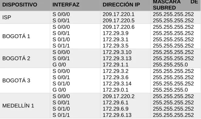
Tabla No. 3: Tabla de enrutamiento
DISPOSITIVO INTERFAZ DIRECCIÓN IP MÁSCARA DE
SUBRED
ISP S 0/0/0
MEDELLÍN 2
S 0/0/0 S 0/0/1 G 0/0
172.29.6.2 172.29.6.5 172.29.4.1
255.255.255.252 255.255.255.252 255.255.255.128
MEDELLÍN 3
S 0/0/0 S 0/0/1 S 0/1/0 G 0/0
172.29.6.10 172.29.6.14 172.29.6.6 172.29.4.129
255.255.255.252 255.255.255.252 255.255.255.252 255.255.255.128
PC0 (50 HOST) NIC DHCP DHCP
PC1 (40 HOST) NIC DHCP DHCP
PC2 (150 HOST) NIC DHCP DHCP
PC3 (200 HOST) NIC DHCP DHCP
Tabla No. 3: Tabla de enrutamiento
Fuente: Elaboración propia
3.4.2. Diagnostico de enrutamiento
Router Bogotá 1
Grafico No. 4: Diagnostico de enrutamiento Bogotá 1
Fuente: Elaboración propia
Router Bogotá 2
Grafico No. 5: Diagnostico de enrutamiento Bogotá 2
Router Bogotá 3
Grafico No. 6: Diagnostico de enrutamiento Bogotá 3
Fuente: Elaboración propia
Router Medellín 1
Grafico No. 7: Diagnostico de enrutamiento Medellín 1
Fuente: Elaboración propia
Router Medellín 2
Grafico No. 8: Diagnostico de enrutamiento Medellín 2
Router Medellín 3
Grafico No. 9: Diagnostico de enrutamiento Medellín 3
Fuente: Elaboración propia
3.5. Verificar el balanceo de carga que presentan los routers.
3.5.1. Balanceo de Carga y Redundancia en Bogota 3 – Bogotá 1 / 3 Respectivamente
Grafico No. 10: Balanceo de carga y redundancia Bogotá 3
Grafico No. 11: Diagnostico de enrutamiento Bogotá 3
Fuente: Elaboración propia
3.5.2. Balanceo de Carga y Redundancia Medellín 3 – Medellín 1 / 3 Respectivamente
Grafico No. 12: Balanceo de carga y redundancia Medellín 3
Fuente: Elaboración propia
Grafico No. 13: Diagnostico de enrutamiento Medellín 3
3.6. Obsérvese en los routers Bogotá1 y Medellín1 cierta similitud por su ubicación, por tener dos enlaces de conexión hacia otro router y por la ruta por defecto que manejan.
3.7. Los routers Medellín2 y Bogotá2 también presentan redes conectadas directamente y recibidas mediante RIP.
3.8. Las tablas de los routers restantes deben permitir visualizar rutas redundantes para el caso de la ruta por defecto.
3.9. El router ISP solo debe indicar sus rutas estáticas adicionales a las directamente conectadas.
Grafico No. 14: Diagnostico de enrutamiento ISP
Fuente: Elaboración propia
4. Deshabilitar la propagación del protocolo RIP.
4.1. Para no propagar las publicaciones por interfaces que no lo requieran se debe deshabilitar la propagación del protocolo RIP, en la siguiente tabla se indican las interfaces de cada router que no necesitan desactivación.
ROUTER INTERFAZ
Bogota1 SERIAL0/0/1; SERIAL0/1/0;
SERIAL0/1/1
Bogota2 SERIAL0/0/0; SERIAL0/0/1
Bogota3 SERIAL0/0/0; SERIAL0/0/1;
SERIAL0/1/0
Medellín1 SERIAL0/0/0; SERIAL0/0/1;
SERIAL0/1/1
Medellín2 SERIAL0/0/0; SERIAL0/0/1
Medellín3 SERIAL0/0/0; SERIAL0/0/1;
SERIAL0/1/0
ISP No lo requiere
Tabla No. 4: Interfaces a desactivar de cada Router
4.2. Verificación del protocolo RIP.
4.2.1. Verificar y documentar las opciones de enrutamiento
configuradas en los routers, como el passive interface para la conexión hacia el ISP, la versión de RIP y las interfaces que participan de la publicación entre otros datos.
4.2.2. Verificar y documentar la base de datos de RIP de cada router, donde se informa de manera detallada de todas las rutas hacia cada red.
5. Configurar encapsulamiento y autenticación PPP.
5.1. Según la topología se requiere que el enlace Medellín1 con ISP sea configurado con autenticación PAT.
Medellín 1
MEDELLIN_1>enable Password:
MEDELLIN_1#config t
Enter configuration commands, one per line. End with CNTL/Z. MEDELLIN_1(config)#username ISP password cisco
MEDELLIN_1(config)#int s0/0/0
MEDELLIN_1(config-if)#encapsulation ppp MEDELLIN_1(config-if)#
%LINEPROTO-5-UPDOWN: Line protocol on Interface Serial0/0/0, changed state to down
MEDELLIN_1(config-if)#ppp pap sent-username MEDELLIN_1 password cisco MEDELLIN_1(config-if)#end
MEDELLIN_1#
%SYS-5-CONFIG_I: Configured from console by console MEDELLIN_1#copy running-config startup-config
Destination filename [startup-config]? Building configuration...
[OK]
MEDELLIN_1#exit
Isp
ISP>enable Password: ISP#config t
Enter configuration commands, one per line. End with CNTL/Z. ISP(config)#username MEDELLIN_1 password cisco
ISP(config-if)#encapsulation ppp ISP(config-if)#
%LINEPROTO-5-UPDOWN: Line protocol on Interface Serial0/0/0, changed state to up
ISP(config-if)#ppp pap sent-username ISP password cisco ISP(config-if)#end
ISP#
%SYS-5-CONFIG_I: Configured from console by console ISP#copy running-config startup-config
Destination filename [startup-config]? Building configuration...
[OK] ISP#exit
Grafico No. 14: Prueba de diagnostico Ping Medellín 1 - ISP
Fuente: Elaboración propia
5.2. El enlace Bogotá1 con ISP se debe configurar con autenticación CHAT.
Bogotá 1
BOGOTA_1>enable Password:
BOGOTA_1#config t
Enter configuration commands, one per line. End with CNTL/Z. BOGOTA_1(config)#username ISP password cisco
BOGOTA_1(config)#int s0/0/0
BOGOTA_1(config-if)#encapsulation ppp BOGOTA_1(config-if)#
%LINEPROTO-5-UPDOWN: Line protocol on Interface Serial0/0/0, changed state to down
BOGOTA_1(config-if)#ppp authentication chap BOGOTA_1(config-if)#end
BOGOTA_1#
%SYS-5-CONFIG_I: Configured from console by console BOGOTA_1#copy running-config startup-config
Building configuration... [OK]
BOGOTA_1#exit
Isp
ISP>enable Password: ISP#config t
Enter configuration commands, one per line. End with CNTL/Z. ISP(config)#username BOGOTA_1 password cisco
ISP(config)#int s0/0/1
ISP(config-if)#encapsulation ppp ISP(config-if)#ppp authentication chap ISP(config-if)#end
ISP#
%SYS-5-CONFIG_I: Configured from console by console ISP#copy running-config startup-config
Destination filename [startup-config]? Building configuration...
[OK] ISP#exit
Grafico No. 15: Prueba de diagnostico Ping ISP – Bogotá 1
Fuente: Elaboración propia
6. Configuración de PAT.
6.1. En la topología, si se activa NAT en cada equipo de salida (Bogotá1 y Medellín1), los routers internos de una ciudad no podrán llegar hasta los routers internos en el otro extremo, sólo existirá comunicación hasta los routers Bogotá1, ISP y Medellín1.
a la dirección de la interfaz serial 0/1/0 del router Medellín1, cómo diferente puerto.
6.3. Proceda a configurar el NAT en el router Bogotá1. Compruebe que la traducción de direcciones indique las interfaces de entrada y de salida. Al realizar una prueba de ping, la dirección debe ser traducida automáticamente a la dirección de la interfaz serial 0/1/0 del router Bogotá1, cómo diferente puerto.
Bogotá 1
BOGOTA_1>enable Password:
BOGOTA_1#config t
Enter configuration commands, one per line. End with CNTL/Z.
BOGOTA_1(config)#ip nat inside source list 1 interface s0/0/0 overload BOGOTA_1(config)#access-list 1 permit 172.29.0.0 0.0.3.255
BOGOTA_1(config)#int s0/0/0 BOGOTA_1(config-if)#ip nat outside BOGOTA_1(config-if)#int s0/0/1 BOGOTA_1(config-if)#ip nat inside BOGOTA_1(config-if)#int s0/1/0 BOGOTA_1(config-if)#ip nat inside BOGOTA_1(config-if)#int s0/1/1 BOGOTA_1(config-if)#ip nat inside BOGOTA_1(config-if)#end
BOGOTA_1#
%SYS-5-CONFIG_I: Configured from console by console BOGOTA_1#copy running-config startup-config
Destination filename [startup-config]? Building configuration...
[OK]
BOGOTA_1#exit
Medellín 1
MEDELLIN_1>enable Password:
MEDELLIN_1#config t
Enter configuration commands, one per line. End with CNTL/Z.
MEDELLIN_1(config)#ip nat inside source list 1 interface s0/0/0 overload MEDELLIN_1(config)#access-list 1 permit 172.29.4.0 0.0.3.255
MEDELLIN_1(config-if)#ip nat inside MEDELLIN_1(config-if)#int s0/1/0 MEDELLIN_1(config-if)#ip nat inside MEDELLIN_1(config-if)#int s0/1/1 MEDELLIN_1(config-if)#ip nat inside MEDELLIN_1(config-if)#end
MEDELLIN_1#
%SYS-5-CONFIG_I: Configured from console by console MEDELLIN_1#copy running-config startup-config
Destination filename [startup-config]? Building configuration...
[OK]
MEDELLIN_1#exit
7. Configuración del servicio DHCP.
7.1. Configurar la red Medellín2 y Medellín3 donde el router Medellín 2 debe ser el servidor DHCP para ambas redes Lan.
7.2. El router Medellín3 deberá habilitar el paso de los mensajes broadcast hacia la IP del router Medellín2.
DHCP en Medellín 2
MEDELLIN_2>enable Password:
MEDELLIN_2#config t
Enter configuration commands, one per line. End with CNTL/Z.
MEDELLIN_2(config)#ip dhcp excluded-address 172.29.4.1 172.29.4.5 MEDELLIN_2(config)#ip dhcp excluded-address 172.29.4.129 172.29.4.133 MEDELLIN_2(config)#ip dhcp pool MEDELLIN_2
MEDELLIN_2(dhcp-config)#network 172.29.4.0 255.255.255.128 MEDELLIN_2(dhcp-config)#default-router 172.29.4.1
MEDELLIN_2(dhcp-config)#dns-server 8.8.8.2 MEDELLIN_2(dhcp-config)#exit
MEDELLIN_2(config)#ip dhcp pool MEDELLIN_3
MEDELLIN_2(dhcp-config)#network 172.29.4.128 255.255.255.128 MEDELLIN_2(dhcp-config)#default-router 172.29.4.129
MEDELLIN_2(dhcp-config)#dns-server 8.8.8.2 MEDELLIN_2(dhcp-config)#exit
MEDELLIN_2(config)#end MEDELLIN_2#
%SYS-5-CONFIG_I: Configured from console by console MEDELLIN_2#copy running-config startup-config
Building configuration... [OK]
MEDELLIN_2#exit
Configuración Router Medellín 3
MEDELLIN_3>enable Password:
MEDELLIN_3#config t
Enter configuration commands, one per line. End with CNTL/Z. MEDELLIN_3(config)#int g0/0
MEDELLIN_3(config-if)#ip helper-address 172.29.6.5 MEDELLIN_3(config-if)#end
MEDELLIN_3#
%SYS-5-CONFIG_I: Configured from console by console MEDELLIN_3#copy running-config startup-config
Destination filename [startup-config]? Building configuration...
[OK]
MEDELLIN_3#exit
Dhcp en Pc0
Grafico No. 16: Configuración DHCP PC0
Fuente: Elaboración propia
DHCP en Pc1
Grafico No. 17: Configuración DHCP PC1
7.3. Configurar la red Bogotá2 y Bogotá3 donde el router Medellín2 debe ser el servidor DHCP para ambas redes Lan.
7.4. Configure el router Bogotá1 para que habilite el paso de los mensajes Broadcast hacia la IP del router Bogotá2.
Configuración Router Bogotá 2
BOGOTA_2>enable Password:
BOGOTA_2#config t
Enter configuration commands, one per line. End with CNTL/Z.
BOGOTA_2(config)#ip dhcp excluded-address 172.29.1.1 172.29.1.5 BOGOTA_2(config)#ip dhcp excluded-address 172.29.0.1 172.29.0.5 BOGOTA_2(config)#ip dhcp pool BOGOTA_2
BOGOTA_2(dhcp-config)#network 172.29.1.0 255.255.255.0 BOGOTA_2(dhcp-config)#default-router 172.29.1.1
BOGOTA_2(dhcp-config)#dns-server 8.8.8.2
BOGOTA_2(dhcp-config)#ip dhcp pool BOGOTA_3
BOGOTA_2(dhcp-config)#network 172.29.0.0 255.255.255.0 BOGOTA_2(dhcp-config)#default-router 172.29.0.1
BOGOTA_2(dhcp-config)#dns-server 8.8.8.2 BOGOTA_2(dhcp-config)#end
BOGOTA_2#
%SYS-5-CONFIG_I: Configured from console by console BOGOTA_2#copy running-config startup-config
Destination filename [startup-config]? Building configuration...
[OK]
BOGOTA_2#exit
Configuración Router Bogotá 3
BOGOTA_3>enable Password:
BOGOTA_3#config t
Enter configuration commands, one per line. End with CNTL/Z. BOGOTA_3(config)#int g0/0
BOGOTA_3(config-if)#ip helper-address 172.29.3.13 BOGOTA_3(config-if)#end
BOGOTA_3#
%SYS-5-CONFIG_I: Configured from console by console BOGOTA_3#copy running-config startup-config
[OK]
BOGOTA_3#exit
DHCP en Pc2
Grafico No. 18: Configuración DHCP PC2
Fuente: Elaboración propia
DHCP en Pc3
Grafico No. 19: Configuración DHCP PC3
Fuente: Elaboración propia
Verificación Conectividad de Pc2 Y Pc3
Grafico No. 20: Prueba diagnóstico ping PC2 – PC3
Comprobación de conexión extremo a extremo luego de haber restringido la comunicación entre los equipos de Bogotá y Medellín
Grafico No. 21: Prueba diagnóstico ping Extremo – Extremo
Escenario 2
Escenario: Una empresa de Tecnología posee tres sucursales distribuidas en las ciudades de Miami, Bogotá y Buenos Aires, en donde el estudiante será el administrador de la red, el cual deberá configurar e interconectar entre sí cada uno de los dispositivos que forman parte del escenario, acorde con los lineamientos establecidos para el direccionamiento IP, protocolos de enrutamiento y demás aspectos que forman parte de la topología de red.
8. Configurar el direccionamiento IP acorde con la topología de red para cada uno de los dispositivos que forman parte del escenario.
8.1. Configuración Inicial
Router R1
Enter configuration commands, one per line. End with CNTL/Z. Router(config)#no ip domain-lookup
Router(config)#hostname R1 R1(config)#enable secret class R1(config)#line console 0 R1(config-line)#password cisco R1(config-line)#login
R1(config-line)#exit R1(config)#line vty 0 4
R1(config-line)#password cisco R1(config-line)#login
R1(config-line)#exit
R1(config)#service password-encryption R1(config)#banner motd #
Enter TEXT message. End with the character '#'.
*** Servicio restringido - Solo se permite acceso a personal autorizado*** # R1(config)#exit
R1#
%SYS-5-CONFIG_I: Configured from console by console
R1#copy running-config startup-config Destination filename [startup-config]? Building configuration...
[OK] R1#exit
Router R2
Router>enable Router#config t
Enter configuration commands, one per line. End with CNTL/Z. Router(config)#no ip domain-lookup
Router(config)#hostname R2 R2(config)#enable secret class R2(config)#line console 0 R2(config-line)#password cisco R2(config-line)#login
R2(config-line)#exit R2(config)#line vty 0 4
R2(config-line)#password cisco R2(config-line)#login
R2(config-line)#exit
Enter TEXT message. End with the character '#'.
*** Servicio restringido - Solo se permite acceso a personal autorizado **** # R2(config)#exit
R2#
%SYS-5-CONFIG_I: Configured from console by console R2#copy running-config startup-config
Destination filename [startup-config]? Building configuration...
[OK] R2#exit
Router R3
Router>enable Router#config t
Enter configuration commands, one per line. End with CNTL/Z. Router(config)#no ip domain-lookup
Router(config)#hostname R3 R3(config)#enable secret class R3(config)#line console 0 R3(config-line)#password cisco R3(config-line)#login
R3(config-line)#exit R3(config)#line vty 0 4
R3(config-line)#password cisco R3(config-line)#login
R3(config-line)#exit
R3(config)#service password-encryption R3(config)#banner motd #
Enter TEXT message. End with the character '#'.
*** Servicio restringido - Solo se permite acceso a personal autorizado *** # R3(config)#exit
R3#
%SYS-5-CONFIG_I: Configured from console by console R3#copy running-config startup-config
Destination filename [startup-config]? Building configuration...
Switch S1
Switch>enable Switch#config t
Enter configuration commands, one per line. End with CNTL/Z. Switch(config)#no ip domain-lookup
Switch(config)#hostname S1 S1(config)#enable secret class S1(config)#line console 0 S1(config-line)#password cisco S1(config-line)#login
S1(config-line)#exit S1(config)#line vty 0 4
S1(config-line)#password cisco S1(config-line)#login
S1(config-line)#exit
S1(config)#service password-encryption S1(config)#banner motd #
Enter TEXT message. End with the character '#'.
**** Servicio restringido - Solo se permite acceso a personal autorizado **** # S1(config)#exit
S1#
%SYS-5-CONFIG_I: Configured from console by console S1#copy running-config startup-config
Destination filename [startup-config]? Building configuration...
[OK] S1#exit
Switch S3
Switch>enable Switch#config t
Enter configuration commands, one per line. End with CNTL/Z. Switch(config)#no ip domain-lookup
Switch(config)#hostname S3 S3(config)#enable secret class S3(config)#line console 0 S3(config-line)#password cisco S3(config-line)#login
S3(config-line)#exit S3(config)#line vty 0 4
S3(config-line)#exit
S3(config)#service password-encryption S3(config)#banner motd #
Enter TEXT message. End with the character '#'.
*** Servicio Restringido - Solo se permite acceso a personal autorizado *** # S3(config)#exit
S3#
%SYS-5-CONFIG_I: Configured from console by console S3#copy running-config startup-config
Destination filename [startup-config]? Building configuration...
[OK] S3#exit
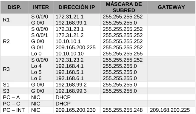
Tabla de direccionamiento IP
DISP. INTER DIRECCIÓN IP MÁSCARA DE
SUBRED GATEWAY
R1 S 0/0/0 G 0/0 172.31.21.1 192.168.99.1 255.255.255.252 255.255.255.0 R2 S 0/0/0 S 0/0/1 G 0/0 G 0/1 Lo 0 172.31.23.1 172.31.21.2 10.10.10.1 209.165.200.225 10.10.10.10 255.255.255.252 255.255.255.252 255.255.255.252 255.255.255.252 255.255.255.255 R3 S 0/0/0 Lo 4 Lo 5 Lo 6 172.31.23.2 192.168.4.1 192.168.5.1 192.168.6.1 255.255.255.252 255.255.255.0 255.255.255.0 255.255.255.0 S1 G 0/0 192.168.99.2 255.255.255.0 S3 G 0/0 192.168.99.3 255.255.255.0
PC – A NIC DHCP
PC – C NIC DHCP
PC – INT NIC 209.165.200.230 255.255.255.248 209.168.200.225
Tabla No. 5: Tabla de direccionamiento IP
Fuente: Elaboración propia
8.2. Direccionamiento IP
Router R1
Enter configuration commands, one per line. End with CNTL/Z. R1(config)#interface s0/0/0
R1(config-if)#description connection to MIAMI R1(config-if)#clock rate 2000000
R1(config-if)#ip address 172.31.21.1 255.255.255.252 R1(config-if)#no shutdown
R1(config-if)#exit
R1(config)#interface G0/0
R1(config-if)#ip address 192.168.99.1 255.255.255.0 R1(config-if)#no shutdown
R1(config-if)#
%LINK-5-CHANGED: Interface GigabitEthernet0/0, changed state to up R1(config-if)#exit
R1(config)#ip route 0.0.0.0 0.0.0.0 s0/0/0
%Default route without gateway, if not a point-to-point interface, may impact performance
R1(config)#end R1#
%SYS-5-CONFIG_I: Configured from console by console R1#copy running-config startup-config
Destination filename [startup-config]? Building configuration...
[OK] R1#exit
Router R2
R2>enable Password: R2#config t
Enter configuration commands, one per line. End with CNTL/Z. R2(config)#interface s0/0/0
R2(config-if)#description connection to BOGOTA R2(config-if)#ip address 172.31.23.1 255.255.255.252 R2(config-if)#clock rate 2000000
R2(config-if)#no shutdown R2(config-if)#exit
R2(config)#interface s0/0/1
R2(config-if)#description connection to BUENOS AIRES R2(config-if)#no clock rate
R2(config-if)#ip address 172.31.21.2 255.255.255.252 R2(config-if)#no shutdown
R2(config-if)#exit
R2(config-if)#description connection to INTERNET PC R2(config-if)#ip address 10.10.10.1 255.255.255.252 R2(config-if)#no shutdown
R2(config-if)#exit
R2(config)#interface g0/1
R2(config-if)#description connection to WEB SERVER R2(config-if)#ip address 209.165.200.225 255.255.255.252 R2(config-if)#no shutdown
R2(config-if)#
%LINK-5-CHANGED: Interface GigabitEthernet0/1, changed state to up R2(config-if)#exit
R2(config)#int loopback 0
R2(config-if)#ip address 10.10.10.10 255.255.255.255 R2(config-if)#description web server simulado
R2(config-if)#exit
R2(config)#ip route 0.0.0.0 0.0.0.0 g0/1
%Default route without gateway, if not a point-to-point interface, may impact performance
R2(config)#exit R2#
%SYS-5-CONFIG_I: Configured from console by console R2#copy running-config startup-config
Destination filename [startup-config]? Building configuration...
[OK] R2#exit
Router R3
R3>enable Password: R3#config t
Enter configuration commands, one per line. End with CNTL/Z. R3(config)#interface s0/0/0
R3(config-if)#description connection to MIAMI R3(config-if)#no clock rate
R3(config-if)#ip address 172.31.23.2 255.255.255.252 R3(config-if)#exit
R3(config)#int loopback 4 R3(config-if)#
%LINK-5-CHANGED: Interface Loopback4, changed state to up
R3(config-if)#ip address 192.168.4.1 255.255.255.0 R3(config-if)#exit
R3(config)#int loopback 5 R3(config-if)#
%LINK-5-CHANGED: Interface Loopback5, changed state to up
%LINEPROTO-5-UPDOWN: Line protocol on Interface Loopback5, changed state to up
R3(config-if)#ip address 192.168.5.1 255.255.255.0 R3(config-if)#exit
R3(config)#int loopback 6 R3(config-if)#
%LINK-5-CHANGED: Interface Loopback6, changed state to up
%LINEPROTO-5-UPDOWN: Line protocol on Interface Loopback6, changed state to up
R3(config-if)#ip address 192.168.6.1 255.255.255.0 R3(config-if)#exit
R3(config)#ip route 0.0.0.0 0.0.0.0 s0/0/0
%Default route without gateway, if not a point-to-point interface, may impact performance
R3(config)#end R3#
%SYS-5-CONFIG_I: Configured from console by console R3#copy running-config startup-config
Destination filename [startup-config]? Building configuration...
[OK] R3#exit
Pc – Internet
Grafico No. 22: Direccionamiento IP PC – Internet
9. Configurar el protocolo de enrutamiento OSPFv2 bajo los siguientes criterios:
OSPFv2 area 0
Configuration Item or Task Specification
Router ID R1 1.1.1.1
Router ID R2 5.5.5.5
Router ID R3 8.8.8.8
Configurar todas las interfaces LAN como pasivas
Establecer el ancho de banda para enlaces
seriales en 256 Kb/s
Ajustar el costo en la métrica de S0/0 a 9500
Tabla No. 6: Tabla de Configuración OSPF v2 area 0
Fuente: Universidad Nacional Abierta y a Distancia UNAD
9.1. Enrutamiento OSPFv2
Router R1
R1>enable Password: R1#config t
Enter configuration commands, one per line. End with CNTL/Z. R1(config)#router ospf 1
R1(config-router)#router-id 1.1.1.1
R1(config-router)#network 172.31.21.0 0.0.0.3 area 0 R1(config-router)#network 172.31.23.0 0.0.0.3 area 0 R1(config-router)#network 10.10.10.0 0.0.0.255 area 0 R1(config-router)#do write
Building configuration... [OK]
R1(config-router)#passive-interface g0/0 R1(config-router)#exit
R1(config)#interface s0/0/0 R1(config-if)#bandwidth 256 R1(config-if)#ip ospf cost 9600 R1(config-if)#end
R1#
Destination filename [startup-config]? Building configuration...
[OK] R1#exit
Router R2
R2>enable Password: R2#config t
Enter configuration commands, one per line. End with CNTL/Z. R2(config)#router ospf 1
R2(config-router)#router-id 5.5.5.5
R2(config-router)#network 172.31.21.0 0.0.0.3 area 0 R2(config-router)#network 172.31.23.0 0.0.0.3 area 0 R2(config-router)#network 10.10.10.0 0.0.0.255 area 0 R2(config-router)#passive-interface g0/1
R2(config-router)#exit R2(config)#interface s0/0/0 R2(config-if)#bandwidth 256 R2(config-if)#ip ospf cost 9500 R2(config-if)#end
R2#
%SYS-5-CONFIG_I: Configured from console by console R2#copy running-config startup-config
Destination filename [startup-config]? Building configuration...
[OK] R2#exit
Router R3
R3>enable Password: R3#config t
Enter configuration commands, one per line. End with CNTL/Z. R3(config)#router ospf 1
R3(config-router)#router-id 8.8.8.8
R3(config-router)#network 172.31.23.0 0.0.0.3 area 0 R3(config-router)#network 192.168.4.0 0.0.3.255 area 0 R3(config-router)#passive-interface lo4
R3(config-router)#exit R3(config)#interface s0/0/0 R3(config-if)#bandwidth 256 R3(config-if)#ip ospf cost 9500 R3(config-if)#end
R3#
%SYS-5-CONFIG_I: Configured from console by console R3#copy running-config startup-config
Destination filename [startup-config]? Building configuration...
[OK] R3#exit
9.2. Verificación de información de OSPF en cada router
Router R1
Grafico No. 23: Prueba de configuración OSPF Router 1
Router R2
Grafico No. 24: Prueba de configuración OSPF Router 2
Fuente: Elaboración propia
Router R3
Grafico No. 25: Prueba de configuración OSPF Router 3
9.3. Visualizar tablas de enrutamiento y routers conectados por OSPFv2 9.4. Visualizar lista resumida de interfaces por OSPF en donde se ilustre el
costo de cada interface
Router R1
Grafico No. 26: Tabla de enrutamiento OSPF Router R1
Fuente: Elaboración propia
Router R2
Grafico No. 27: Tabla de enrutamiento OSPF Router R2
Router R3
Grafico No. 28: Tabla de enrutamiento OSPF Router R3
Fuente: Elaboración propia
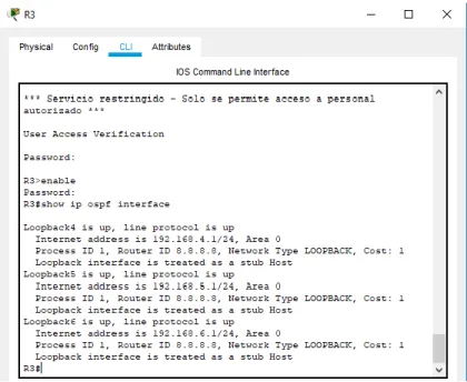
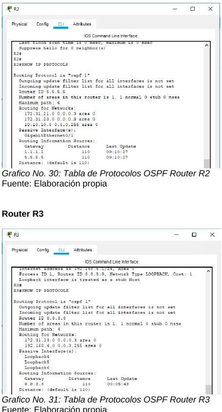
9.5. Visualizar el OSPF Process ID, Router ID, Address summarizations, Routing Networks, and passive interfaces configuradas en cada router.
ROUTER R1
Grafico No. 29: Tabla de Protocolos OSPF Router R1
Router R2
Grafico No. 30: Tabla de Protocolos OSPF Router R2
Fuente: Elaboración propia
Router R3
Grafico No. 31: Tabla de Protocolos OSPF Router R3
9.6. Configurar VLANs, Puertos troncales, puertos de acceso, encapsulamiento, Inter-VLAN Routing y Seguridad en los Switches acorde a la topología de red establecida.
Vlan´S Switch S1
S1>enable Password: S1#config t
Enter configuration commands, one per line. End with CNTL/Z. S1(config)#vlan 30
S1(config-vlan)#name ADMINISTRATION S1(config-vlan)#exit
S1(config)#vlan 40
S1(config-vlan)#name MERCADEO S1(config-vlan)#exit
S1(config)#vlan 200
S1(config-vlan)#name MANTENIMIENTO S1(config-vlan)#exit
S1(config)#end S1#
%SYS-5-CONFIG_I: Configured from console by console S1#copy running-config startup-config
Destination filename [startup-config]? Building configuration...
[OK] S1#exit
Vlan´S Switch S3
S3>enable Password: S3#config t
Enter configuration commands, one per line. End with CNTL/Z. S3(config)#vlan 30
S3(config-vlan)#name ADMINISTRATION S3(config-vlan)#exit
S3(config)#vlan 40
S3(config-vlan)#name MERCADEO S3(config-vlan)#exit
S3(config)#vlan 200
S3(config-vlan)#name MANTENIMIENTO S3(config-vlan)#exit
S3#
%SYS-5-CONFIG_I: Configured from console by console S3#copy running-config startup-config
Destination filename [startup-config]? Building configuration...
[OK] S3#exit
9.7. En el Switch 3 deshabilitar DNS lookup
S3>enable Password: S3#config t
Enter configuration commands, one per line. End with CNTL/Z. S3(config)#no ip domain-lookup
S3(config)#end S3#
%SYS-5-CONFIG_I: Configured from console by console S3#copy running-config startup-config
Destination filename [startup-config]? Building configuration...
[OK] S3#exit
9.8. Configuración de puertos troncales
Switch S1
S1>enable Password: S1#config t
Enter configuration commands, one per line. End with CNTL/Z. S1(config)#int f0/3
S1(config-if)#switchport mode trunk S1(config-if)#
%LINEPROTO-5-UPDOWN: Line protocol on Interface FastEthernet0/3, changed state to down
%LINEPROTO-5-UPDOWN: Line protocol on Interface FastEthernet0/3, changed state to up
S1(config-if)#switchport trunk native vlan 1 S1(config-if)#int f0/24
%LINEPROTO-5-UPDOWN: Line protocol on Interface FastEthernet0/24, changed state to down
%LINEPROTO-5-UPDOWN: Line protocol on Interface FastEthernet0/24, changed state to up
S1(config-if)#switchport trunk native vlan 1 S1(config-if)#no shutdown
S1(config-if)#int range fa0/1-2, fa0/4-24 S1(config-if-range)#switchport mode access S1(config-if-range)#int f0/1
S1(config-if)#switchport mode access S1(config-if)#switchport access vlan 30 S1(config-if)#int range fa0/1-2, fa0/4-24 S1(config-if-range)#shutdown
%LINK-5-CHANGED: Interface FastEthernet0/2, changed state to administratively down
%LINK-5-CHANGED: Interface FastEthernet0/4, changed state to administratively down
%LINK-5-CHANGED: Interface FastEthernet0/5, changed state to administratively down
%LINK-5-CHANGED: Interface FastEthernet0/6, changed state to administratively down
%LINK-5-CHANGED: Interface FastEthernet0/7, changed state to administratively down
%LINK-5-CHANGED: Interface FastEthernet0/8, changed state to administratively down
%LINK-5-CHANGED: Interface FastEthernet0/9, changed state to administratively down
%LINK-5-CHANGED: Interface FastEthernet0/10, changed state to administratively down
%LINK-5-CHANGED: Interface FastEthernet0/11, changed state to administratively down
%LINK-5-CHANGED: Interface FastEthernet0/12, changed state to administratively down
%LINK-5-CHANGED: Interface FastEthernet0/13, changed state to administratively down
%LINK-5-CHANGED: Interface FastEthernet0/14, changed state to administratively down
%LINK-5-CHANGED: Interface FastEthernet0/15, changed state to administratively down
%LINK-5-CHANGED: Interface FastEthernet0/16, changed state to administratively down