DIPLOMADO DE PROFUNDIZACIÓN CISCO (DISEÑO E IMPLEMENTACIÓN DE SOLUCIONES INTEGRADAS LAN / WAN
ANDRES FRANCISCO ANACONA
UNIVERSIDAD NACIONAL ABIERTA Y A DISTANCI ESCUELA CIENCIAS BASICAS E INGENIERÍA
INGENIERIA DE TELECOMUNICACIONES BOGOTA D.C.
PRUEB DE HABILIDADES CCNA CISCO
ANDRES FRANCISCO ANACONA
Diplomado de profundizacion para optar al título de Ingeniero de Telecomunaciones
Ingeniero Juan Carlos Vesga
UNIVERSIDAD NACIONAL ABIERTA Y A DISTANCI ESCUELA CIENCIAS BASICAS E INGENIERÍA
INGENIERIA DE TELECOMUNICACIONES BOGOTA D.C.
Nota de aceptación:
Aprobado por el Comité de Grado en cumplimiento de los requisitos exigidos por la Universidad Nacional Abierta y A distancia UNAD para optar al título Ingeniero de elcomunicaciones
Jurado
Jurado
Dedico este trabajo principalmente a Dios, por haberme dado la vida y permitirme el haber llegado hasta este momento tan importante de mi formación profesional. A mi madre y mi madrina , por ser el pilar más importante y por demostrarme siempre su cariño y apoyo incondicional sin importar nuestras diferencias de opiniones. A mi padre, a pesar de nuestra distancia física, siento que estás conmigo siempre y aunque nos faltaron muchas cosas por vivir juntos, sé que este momento hubiera sido tan especial para ti como lo es para mí. A mi conyugue , a quien quiero con todas la fuerzas de mi ser , por compartir momentos significativos conmigo y por siempre estar dispuesta a escucharme y ayudarme en cualquier momento. A Isabella, porque te amo infinitamente hija. A mis compañeros y tutores , porque sin el equipo que formamos, no hubiéramos logrado esta meta.
“Así como la naturaleza no ha hecho provisión alguna para que mi cuerpo tolere el dolor, tampoco ha hecho provisión para que mi vida sufra el fracaso. El fracaso, como el dolor, es ajeno a mi vida."
AGRADECIMIENTOS
CONTENIDO
pág.
GLOSARIO ¡ERROR! MARCADOR NO DEFINIDO.
RESUMEN 10
INTRODUCCIÓN 12
1. ESCENARIO 1 13
2. TOPOLOGIA 13
3. PARTE 1: CONFIGURACIÓN DEL ENRUTAMIENTO 14
3.1.1 Comandos ejecutados en ISP 14
3.1.2 Comandos ejecutados en router Medellin 1 15 3.1.3 Comandos ejecutados en router Medellin 2 16 3.1.4 Comandos ejecutados en router Medellin 17 3.1.5 Comandos ejecutados en router Bogota 1 18 3.1.6 Comandos ejecutados en router Bogota 1 19 3.1.7 Comandos ejecutados en router Bogota 20
3.2 COMANDOS USADOS RUTA ESTATICA ISP 20
4. PARTE 2: TABLA DE ENRUTAMIENTO. 21
5. PARTE 3: DESHABILITAR LA PROPAGACIÓN DEL PROTOCOLO RIP. 25
7. PARTE 5: CONFIGURAR ENCAPSULAMIENTO Y AUTENTICACIÓN
PPP. 33
8. PARTE 6: CONFIGURACIÓN DE NAT. 36
9. PARTE 7: CONFIGURACIÓN DEL SERVICIO DHCP. 39
10. ESCENARIO 2 42
10.1 CONFIGURAR EL DIRECCIONAMIENTO IP ACORDE CON LA
TOPOLOGÍA 42
10.2 CONFIGURAR EL PROTOCOLO DE ENRUTAMIENTO OSPFV2
BAJO LOS SIGUIENTES CRITERIOS: 45
10.3 VERIFICAR INFORMACIÓN DE OSPF 47
10.3.1 Visualizar tablas de enrutamiento y routers conectados por
OSPFv2 47
10.3.2 Visualizar lista resumida de interfaces por OSPF en donde se
ilustre el costo de cada interface 49
10.3.3 Visualizar el OSPF Process ID, Router ID, Address summarizations, Routing Networks, and passive interfaces configuradas en cada router. 51 10.3.4 Configurar VLANs, Puertos troncales, puertos de acceso,
encapsulamiento, Inter-VLAN Routing y Seguridad en los Switches
acorde a la topología de red establecida. 51
10.3.5 En el Switch 3 deshabilitar DNS lookup 55 10.3.6 Asignar direcciones IP a los Switches acorde a los lineamientos. 55 10.3.7 Desactivar todas las interfaces que no sean utilizadas en el
esquema de red. 56
10.3.8 Implement DHCP and NAT for IPv4 56
10.3.9 Reservar las primeras 30 direcciones IP de las VLAN 30 y 40 para
configuraciones estáticas. 57
internet 57 10.3.11 Configurar al menos dos listas de acceso de tipo estándar a su
criterio en para restringir o permitir tráfico desde R1 o R3 hacia R2. 58
10.3.12 Configurar al menos dos listas de acceso de tipo extendido o nombradas a su criterio en para restringir o permitir tráfico desde R1 o
R3 hacia R2. 58
10.3.13 Verificar procesos de comunicación y redireccionamiento de
tráfico en los routers mediante el uso de Ping y Traceroute. 59
11. CONCLUSIONES 65
12. BIBLIOGRAFÍA O REFERENCIAS 66
RESUMEN
La evaluación denominada “Prueba de habilidades prácticas”, forma parte de las actividades evaluativas del Diplomado de Profundización CCNA, y busca identificar el grado de desarrollo de competencias y habilidades que fueron adquiridas a lo largo del diplomado. Lo esencial es poner a prueba los niveles de comprensión y solución de problemas relacionados con diversos aspectos de Networking.
Para esta actividad, se dispone de dos (2) escenarios propuestos, acompañado de los respectivos procesos de documentación de la solución, correspondientes al registro de la configuración de cada uno de los dispositivos, la descripción detallada del paso a paso de cada una de las etapas realizadas durante su desarrollo, el registro de los procesos de verificación de conectividad mediante el uso de comandos ping, traceroute, show ip route, entre otros.
Teniendo en cuenta que la Prueba de habilidades está conformada por dos (2) escenarios, se realiza el proceso de configuración de usando cualquiera de las siguientes herramientas: Packet Tracer.
Palabras clave:
ABSTRACT
The evaluation called "Test of practical skills", is part of the evaluation activities of the CCNA Deepening Diploma, and seeks to identify the degree of development of skills and abilities that were acquired throughout the course. The essential thing is to test the levels of understanding and solving problems related to various aspects of Networking.
For this activity, two (2) proposed scenarios are available, accompanied by the respective documentation processes of the solution, corresponding to the registration of the configuration of each of the devices, the detailed description of the step by step of each of the stages carried out during its development, the registration of connectivity verification processes through the use of ping, traceroute, show ip route, among others.
INTRODUCCIÓN
Este informe es el producto de una serie de lecturas y estudios del material propuesto en el diplomado de profundizacion Cisco más específicamente en diseño e implementación de soluciones integradas lan / wan CCNA 1 y CCNA2 . Contenido metodológico del curso, así como también los adquiridos a lo largo de nuestro desarrollo académico de ingeniería.
La prueba prueba de habilidades se desarrollo con Packet Tracer para afianzar conocimientos prácticos en ACL, NAT, OSPFv2, DHCPv4, VLAN entre otros. Se Logró diseñar y efectuar la configuración exigida por la prácticas Fue fundamental para armar esta topología, comparar técnicas de seguridad y control, explicar funciones de las capas de enlace y acceso, probar cables y hacer diferentes tipos de pruebas de acuerdo a los parámetros básicos requeridos por los dispositivos, comprobando conectividad entre las diferentes LAN
1. ESCENARIO 1
Una empresa posee sucursales distribuidas en las ciudades de Bogotá y Medellín, en donde el estudiante será el administrador de la red, el cual deberá configurar e interconectar entre sí cada uno de los dispositivos que forman parte del escenario, acorde con los lineamientos establecidos para el direccionamiento IP, protocolos de enrutamiento y demás aspectos que forman parte de la topología de red.
2. TOPOLOGIA
Este escenario plantea el uso de RIP como protocolo de enrutamiento, considerando que se tendran rutas por defecto redistribuidas; asimismo, habilitar el encapsulamiento PPP y su autenticación.
Los routers Bogota2 y medellin2 proporcionan el servicio DHCP a su propia red LAN y a los routers 3 de cada ciudad.
Debe configurar PPP en los enlaces hacia el ISP, con autenticación.
3. PARTE 1: CONFIGURACIÓN DEL ENRUTAMIENTO
Nota: Se configura el direccionamiento en los Reuter Como trabajo inicial se debe realizar lo siguiente.
Realizar las rutinas de diagnóstico y dejar los equipos listos para su configuración (asignar nombres de equipos, asignar claves de seguridad, etc).
no ip domain-lookup
service password-encryption enable secret class
banner motd %Acceso Restringido% ip domain-name unad.cisco
line console 0 password unad login
line vty 0 15 password unad login
3.1.1 Comandos ejecutados en ISP
ISP#conf t
Enter configuration commands, one per line. End with CNTL/Z. ISP(config)#int s0/0
%Invalid interface type and number ISP(config)#int s0/0/0
ISP(config-if)#descrip
ISP(config-if)#description ISP-MEDELLIN1
ISP(config-if)#ip add 209.17.220.1 255.255.255.252 ISP(config-if)#clock rate 128000
ISP(config-if)#no shu
ISP#conf t
Enter configuration commands, one per line. End with CNTL/Z. ISP(config)#int s0/1
%Invalid interface type and number ISP(config)#int s0/0/1
ISP(config-if)#descrip
ISP(config-if)#description ISP-BOGOTA1
ISP(config-if)#clock rate 128000 ISP(config-if)#no shu
RIP
ISP>enable ISP#configure ter
Enter configuration commands, one per line. End with CNTL/Z. ISP(config)#router rip
ISP(config-router)#version 2
ISP(config-router)#network 209.17.220.0
Desactivacion sumatoria automatica
ISP(config-router)#no auto-sumary
3.1.2 Comandos ejecutados en router Medellin 1
MEDELLIN1>enable MEDELLIN1#confi ter MEDELLIN1#confi terminal
Enter configuration commands, one per line. End with CNTL/Z. MEDELLIN1(config)#hostname MEDELLIN1
MEDELLIN1(config)#int s 0/0/0 MEDELLIN1(config-if)#descri
MEDELLIN1(config-if)#description MEDELLIN1-ISP
MEDELLIN1(config-if)#ip add 209.17.220.2 255.255.255.252 MEDELLIN1(config-if)#clock rate 128000
This command applies only to DCE interfaces MEDELLIN1(config-if)#no shu
MEDELLIN1(config-if)#
%LINK-5-CHANGED: Interface Serial0/0/0, changed state to up
MEDELLIN1(config)#int s 0/0/1
MEDELLIN1(config-if)#ip add 172.29.6.13 255.255.255.252 MEDELLIN1(config-if)#clock rate 128000
MEDELLIN1(config-if)#no shu
MEDELLIN1(config-if)#int s 0/1/0
MEDELLIN1(config-if)#description MEDELLIN1-MEDELLIN MEDELLIN1(config-if)#ip add 172.29.6.9 255.255.255.252 MEDELLIN1(config-if)#clock rate 128000
MEDELLIN1(config)#int s 0/1/1
MEDELLIN1(config-if)#ip add 172.29.6.1 255.255.255.252 MEDELLIN1(config-if)#clock rate 128000
MEDELLIN1(config-if)#no shu MEDELLIN1(config)#router rip MEDELLIN1(config-router)#version 2 MEDELLIN1(config-router)#network 172.29.0.0 MEDELLIN1(config-router)#no auto- MEDELLIN1(config-router)#no auto-summary
3.1.3 Comandos ejecutados en router Medellin 2
Router>enable Router#conf ter Router#conf terminal
Enter configuration commands, one per line. End with CNTL/Z. Router(config)#hostname MEDELLIN2
MEDELLIN2(config)#int s0/0/0
MEDELLIN2(config-if)#ip add 172.29.6.2 255.255.255.252 MEDELLIN2(config-if)#clock rate 128000
This command applies only to DCE interfaces MEDELLIN2(config-if)#no shu
MEDELLIN2(config)#int s0/0/1
MEDELLIN2(config-if)#ip add 172.29.6.5 255.255.255.252 MEDELLIN2(config-if)#clock rate 128000
MEDELLIN2(config-if)#no shu
MEDELLIN2(config)#int g0/0
MEDELLIN2(config-if)#ip add 172.29.4.1 255.255.255.128 MEDELLIN2(config-if)#clock rate 128000
^
% Invalid input detected at '^' marker.
3.1.4 Comandos ejecutados en router Medellin
Router>enable
Router#configure terminal
Enter configuration commands, one per line. End with CNTL/Z. Router(config)#hostname MEDELLIN
MEDELLIN(config)#int s0/0/0 MEDELLIN(config-if)#descr
MEDELLIN(config-if)#description MEDELLIN-MEDELLIN1 MEDELLIN(config-if)#ip add
MEDELLIN(config-if)#ip address 172.29.6.14 255.255.255.252 MEDELLIN(config-if)#clock rate 128000
This command applies only to DCE interfaces MEDELLIN(config-if)#no shu
MEDELLIN(config)#int s0/0/1
MEDELLIN(config-if)#ip address 172.29.6.10 255.255.255.252 MEDELLIN(config-if)#clock rate 128000
MEDELLIN(config-if)#no shu
MEDELLIN(config)#int s0/1/0
MEDELLIN(config-if)#ip address 172.29.6.6 255.255.255.252 MEDELLIN(config-if)#clock rate 128000
This command applies only to DCE interfaces MEDELLIN(config-if)#no shu
MEDELLIN(config)#int g0/0
MEDELLIN(config-if)#ip address 172.29.4.2 255.255.255.128 MEDELLIN(config-if)#clock rate 128000
^
% Invalid input detected at '^' marker.
3.1.5 Comandos ejecutados en router Bogota 1
Router>enable
Router#configure terminal
Enter configuration commands, one per line. End with CNTL/Z. Router(config)#hostname BOGOTA1
BOGOTA1(config)#int s 0/0/0
BOGOTA1(config-if)#ip add 209.17.220.6 255.255.255.252 BOGOTA1(config-if)#clock rate 128000
This command applies only to DCE interfaces BOGOTA1(config-if)#no shu
BOGOTA1(config-if)#
%LINK-5-CHANGED: Interface Serial0/0/0, changed state to up
BOGOTA1(config-if)#
%LINEPROTO-5-UPDOWN: Line protocol on Interface Serial0/0/0, changed state to up
descr
BOGOTA1(config-if)#description BOGOTA1-ISP BOGOTA1(config-if)#end
BOGOTA1(config)#int s 0/0/1
BOGOTA1(config-if)#ip add 172.29.3.1 255.255.255.252 BOGOTA1(config-if)#clock rate 128000
BOGOTA1(config-if)#no shu
BOGOTA1(config-if)#int s 0/1/0
BOGOTA1(config-if)#description BOGOTA2-BOGOTA1 BOGOTA1(config-if)#ip add 172.29.3.5 255.255.255.252 BOGOTA1(config-if)#clock rate 128000
BOGOTA1(config-if)#no shu
BOGOTA1(config)#int s 0/1/1
BOGOTA1(config-if)#DESCription BOGOTA1-BOGOTA BOGOTA1(config-if)#ip add 172.29.3.9 255.255.255.252 BOGOTA1(config-if)#clock rate
% Incomplete command.
BOGOTA1(config-if)#clock rate 128000 BOGOTA1(config-if)#no shu
BOGOTA1(config)#router rip BOGOTA1(config-router)#version 2
BOGOTA1(config-router)#no auto-
BOGOTA1(config-router)#no auto-summary
3.1.6 Comandos ejecutados en router Bogota 1
BOGOTA2(config)#int S0/0/0 BOGOTA2(config-if)#descip BOGOTA2(config-if)#descrip
BOGOTA2(config-if)#description BOGOTA2-BOGOTA1 BOGOTA2(config-if)#ip add 172.29.3.2 255.255.255.252 BOGOTA2(config-if)#clock rate 128000
This command applies only to DCE interfaces BOGOTA2(config-if)#no shu
BOGOTA2(config-if)#int S0/0/1
BOGOTA2(config-if)#description BOGOTA1-BOGOTA2 BOGOTA2(config-if)#ip add 172.29.3.6 255.255.255.252 BOGOTA2(config-if)#clock rate 128000
This command applies only to DCE interfaces BOGOTA2(config-if)#no shu
BOGOTA2(config)#int S0/1/1
BOGOTA2(config-if)#description BOGOTA2-BOGOTA BOGOTA2(config-if)#ip add 172.29.3.13 255.255.255.252 BOGOTA2(config-if)#clock rate 128000
BOGOTA2(config-if)#no shu
BOGOTA2(config-if)#int g0/0
BOGOTA2(config-if)#description BOGOTA2-PC0 BOGOTA2(config-if)#ip add 172.29.0.1 255.255.255.0 BOGOTA2(config-if)#clock rate 128000
BOGOTA2(config)#router rip BOGOTA2(config-router)#version 2
BOGOTA2(config-router)#network 172.29.0.0 BOGOTA2(config-router)#no auto-
3.1.7 Comandos ejecutados en router Bogota
Router>enable
Router#configure terminal
Enter configuration commands, one per line. End with CNTL/Z. Router(config)#hostname BOGOTA
BOGOTA(config)#int s0/0/0 BOGOTA(config-if)#descrip
BOGOTA(config-if)#description BOGOTA-BOGOTA1 BOGOTA(config-if)#ip add 172.29.3.10 255.255.255.252 BOGOTA(config-if)#clock rate 128000
This command applies only to DCE interfaces BOGOTA(config-if)#no shu
BOGOTA(config-if)#int s0/0/1
BOGOTA(config-if)#description BOGOTA-BOGOTA2 BOGOTA(config-if)#ip add 172.29.3.10 255.255.255.254 Bad mask /31 for address 172.29.3.10
BOGOTA(config-if)#ip add 172.29.3.14 255.255.255.252 BOGOTA(config-if)#clock rate 128000
This command applies onl
3.2 COMANDOS USADOS RUTA ESTATICA ISP
El router ISP deberá tener una ruta estática dirigida hacia cada red interna de Bogotá y Medellín para el caso se sumarizan las subredes de cada uno a /2
ISP(config)#ip route 172.29.4.0 255.255.252.0 s0/0/0 ISP(config)#ip route 172.29.0.0 255.255.252.0 s0/0/1 ISP(config)#ip route 172.29.4.128 255.255.255.252 s0/0/0 ISP(config)#ip route 172.29.1.0 255.255.255.0 s0/0/1
MEDELLIN1>ena MEDELLIN1#conf t
Enter configuration commands, one per line. End with CNTL/Z. MEDELLIN1(config)#ip route 0.0.0.0 0.0.0.0 209.17.220.1 MEDELLIN1(config)#exit
BOGOTA1>ena BOGOTA1#conf t
Enter configuration commands, one per line. End with CNTL/Z. BOGOTA1(config)#ip route 0.0.0.0 0.0.0.0 209.17.220.5
4. PARTE 2: TABLA DE ENRUTAMIENTO.
a) Verificar la tabla de enrutamiento en cada uno de los routers para comprobar las redes y sus rutas.
ISP#show ip route
Codes: L - local, C - connected, S - static, R - RIP, M - mobile, B - BGP D - EIGRP, EX - EIGRP external, O - OSPF, IA - OSPF inter area N1 - OSPF NSSA external type 1, N2 - OSPF NSSA external type 2 E1 - OSPF external type 1, E2 - OSPF external type 2, E - EGP i - IS-IS, L1 - IS-IS level-1, L2 - IS-IS level-2, ia - IS-IS inter area * - candidate default, U - per-user static route, o - ODR
P - periodic downloaded static route
Gateway of last resort is not set
172.29.0.0/16 is variably subnetted, 7 subnets, 3 masks
S 172.29.0.0/22 is directly connected, Serial0/0/1
S 172.29.0.0/30 is directly connected, Serial0/0/1
[1/0] via 172.29.3.0 [1/0] via 172.29.4.0 [1/0] via 172.29.6.0
S 172.29.1.0/24 is directly connected, Serial0/0/0
is directly connected, Serial0/0/1
S 172.29.4.0/22 is directly connected, Serial0/0/0
S 172.29.4.0/30 is directly connected, Serial0/0/0
[1/0] via 172.29.6.0
S 172.29.4.128/30 is directly connected, Serial0/0/0
MEDELLIN1#sh ip route
Codes: L - local, C - connected, S - static, R - RIP, M - mobile, B - BGP D - EIGRP, EX - EIGRP external, O - OSPF, IA - OSPF inter area N1 - OSPF NSSA external type 1, N2 - OSPF NSSA external type 2 E1 - OSPF external type 1, E2 - OSPF external type 2, E - EGP i - IS-IS, L1 - IS-IS level-1, L2 - IS-IS level-2, ia - IS-IS inter area * - candidate default, U - per-user static route, o - ODR
P - periodic downloaded static route
Gateway of last resort is 209.17.220.1 to network 0.0.0.0
172.29.0.0/16 is variably subnetted, 4 subnets, 2 masks
L 172.29.6.9/32 is directly connected, Serial0/1/0
C 172.29.6.12/30 is directly connected, Serial0/0/1
L 172.29.6.13/32 is directly connected, Serial0/0/1
209.17.220.0/24 is variably subnetted, 2 subnets, 2 masks
C 209.17.220.0/30 is directly connected, Serial0/0/0
L 209.17.220.2/32 is directly connected, Serial0/0/0
S* 0.0.0.0/0 [1/0] via 209.17.220.1
MEDELLIN#sh ip route
Codes: L - local, C - connected, S - static, R - RIP, M - mobile, B - BGP D - EIGRP, EX - EIGRP external, O - OSPF, IA - OSPF inter area N1 - OSPF NSSA external type 1, N2 - OSPF NSSA external type 2 E1 - OSPF external type 1, E2 - OSPF external type 2, E - EGP i - IS-IS, L1 - IS-IS level-1, L2 - IS-IS level-2, ia - IS-IS inter area * - candidate default, U - per-user static route, o - ODR
P - periodic downloaded static route
Gateway of last resort is not set
172.29.0.0/16 is variably subnetted, 8 subnets, 3 masks
C 172.29.4.0/25 is directly connected, GigabitEthernet0/0
S 172.29.4.0/30 [1/0] via 172.29.6.0
L 172.29.4.2/32 is directly connected, GigabitEthernet0/0
S 172.29.6.0/30 [1/0] via 172.29.4.0
C 172.29.6.4/30 is directly connected, Serial0/1/0
L 172.29.6.6/32 is directly connected, Serial0/1/0
C 172.29.6.12/30 is directly connected, Serial0/0/0
L 172.29.6.14/32 is directly connected, Serial0/0/0
MEDELLIN2#show ip route
Codes: L - local, C - connected, S - static, R - RIP, M - mobile, B - BGP D - EIGRP, EX - EIGRP external, O - OSPF, IA - OSPF inter area N1 - OSPF NSSA external type 1, N2 - OSPF NSSA external type 2 E1 - OSPF external type 1, E2 - OSPF external type 2, E - EGP i - IS-IS, L1 - IS-IS level-1, L2 - IS-IS level-2, ia - IS-IS inter area * - candidate default, U - per-user static route, o - ODR
P - periodic downloaded static route
Gateway of last resort is not set
172.29.0.0/16 is variably subnetted, 7 subnets, 3 masks C 172.29.4.0/25 is directly connected, GigabitEthernet0/0 L 172.29.4.1/32 is directly connected, GigabitEthernet0/0 C 172.29.6.0/30 is directly connected, Serial0/0/0
C 172.29.6.4/30 is directly connected, Serial0/0/1 L 172.29.6.5/32 is directly connected, Serial0/0/1
R 172.29.6.12/30 [120/1] via 172.29.6.6, 00:00:08, Serial0/0/1
BOGOTA1(config)#end BOGOTA1#
%SYS-5-CONFIG_I: Configured from console by console sh ip route
Codes: L - local, C - connected, S - static, R - RIP, M - mobile, B - BGP D - EIGRP, EX - EIGRP external, O - OSPF, IA - OSPF inter area N1 - OSPF NSSA external type 1, N2 - OSPF NSSA external type 2 E1 - OSPF external type 1, E2 - OSPF external type 2, E - EGP i - IS-IS, L1 - IS-IS level-1, L2 - IS-IS level-2, ia - IS-IS inter area * - candidate default, U - per-user static route, o - ODR
P - periodic downloaded static route
Gateway of last resort is 209.17.220.5 to network 0.0.0.0
172.29.0.0/16 is variably subnetted, 8 subnets, 3 masks R 172.29.0.0/24 [120/1] via 172.29.3.2, 00:00:22, Serial0/0/1
[120/1] via 172.29.3.6, 00:00:22, Serial0/1/0 C 172.29.3.0/30 is directly connected, Serial0/0/1 L 172.29.3.1/32 is directly connected, Serial0/0/1 C 172.29.3.4/30 is directly connected, Serial0/1/0 L 172.29.3.5/32 is directly connected, Serial0/1/0 C 172.29.3.8/30 is directly connected, Serial0/1/1 L 172.29.3.9/32 is directly connected, Serial0/1/1
R 172.29.3.12/30 [120/1] via 172.29.3.2, 00:00:22, Serial0/0/1 [120/1] via 172.29.3.6, 00:00:22, Serial0/1/0
209.17.220.0/24 is variably subnetted, 2 subnets, 2 masks
BOGOTA2>enabl BOGOTA2#sh ip route
Codes: L - local, C - connected, S - static, R - RIP, M - mobile, B - BGP D - EIGRP, EX - EIGRP external, O - OSPF, IA - OSPF inter area N1 - OSPF NSSA external type 1, N2 - OSPF NSSA external type 2 E1 - OSPF external type 1, E2 - OSPF external type 2, E - EGP i - IS-IS, L1 - IS-IS level-1, L2 - IS-IS level-2, ia - IS-IS inter area * - candidate default, U - per-user static route, o - ODR
P - periodic downloaded static route
Gateway of last resort is not set
L 172.29.0.1/32 is directly connected, GigabitEthernet0/0 C 172.29.3.0/30 is directly connected, Serial0/0/0
L 172.29.3.2/32 is directly connected, Serial0/0/0 C 172.29.3.4/30 is directly connected, Serial0/0/1 L 172.29.3.6/32 is directly connected, Serial0/0/1
R 172.29.3.8/30 [120/1] via 172.29.3.1, 00:00:09, Serial0/0/0 [120/1] via 172.29.3.5, 00:00:09, Serial0/0/1
C 172.29.3.12/30 is directly connected, Serial0/1/1 L 172.29.3.13/32 is directly connected, Serial0/1/1 BOGOTA>enabl
BOGOTA#sh ip route
Codes: L - local, C - connected, S - static, R - RIP, M - mobile, B - BGP D - EIGRP, EX - EIGRP external, O - OSPF, IA - OSPF inter area N1 - OSPF NSSA external type 1, N2 - OSPF NSSA external type 2 E1 - OSPF external type 1, E2 - OSPF external type 2, E - EGP i - IS-IS, L1 - IS-IS level-1, L2 - IS-IS level-2, ia - IS-IS inter area * - candidate default, U - per-user static route, o - ODR
P - periodic downloaded static route
Gateway of last resort is not set
172.29.0.0/16 is variably subnetted, 6 subnets, 3 masks C 172.29.1.0/24 is directly connected, GigabitEthernet0/0 L 172.29.1.1/32 is directly connected, GigabitEthernet0/0 C 172.29.3.8/30 is directly connected, Serial0/0/0
L 172.29.3.10/32 is directly connected, Serial0/0/0 C 172.29.3.12/30 is directly connected, Serial0/0/1 L 172.29.3.14/32 is directly connected, Serial0/0/1
5. PARTE 3: DESHABILITAR LA PROPAGACIÓN DEL PROTOCOLO RIP.
Comando usados para evitar la propagación del protocolo RIP innecesario por ciertas interfaces de cada Router de la red:
MEDELLIN1#configure ter
Enter configuration commands, one per line. End with CNTL/Z. MEDELLIN1(config)#router rip
MEDELLIN1(config-router)#version 2 MEDELLIN1(config-router)#passive-
MEDELLIN1(config-router)#passive-interface s0/0/1 MEDELLIN1(config-router)#
MEDELLIN2(config)#router rip
MEDELLIN2(config-router)#version 2 MEDELLIN2(config-router)#passive-
MEDELLIN2(config-router)#passive-interface g0/0 MEDELLIN2(config-router)#
MEDELLIN(config)#router rip
MEDELLIN(config-router)#passive- MEDELLIN(config-router)#passive-interface g0/0 MEDELLIN(config-router)#passive-interface s0/1/0 MEDELLIN(config-router) BOGOTA1(config)#router rip BOGOTA1(config-router)#version 2 BOGOTA1(config-router)#passive- BOGOTA1(config-router)#passive-interface s0/0/0 BOGOTA1(config-router)#end BOGOTA1# BOGOTA2(config)#router rip BOGOTA2(config-router)#version 2 BOGOTA2(config-router)#passive- BOGOTA2(config-router)#passive-interface g0/0 BOGOTA2(config-router)#passive-interface S0/1/1 BOGOTA2(config-router)#end BOGOTA>ena BOGOTA#conf t
Enter configuration commands, one per line. End with CNTL/Z. BOGOTA(config)#router rip BOGOTA(config-router)#version 2 BOGOTA(config-router)#passive- BOGOTA(config-router)#passive-interface g0/0 BOGOTA(config-router)#end BOGOTA#
6. PARTE 4: VERIFICACIÓN DEL PROTOCOLO RIP.
7. PARTE 5: CONFIGURAR ENCAPSULAMIENTO Y AUTENTICACIÓN PPP.
Según la topología se requiere que el enlace Medellín1 con ISP sea configurado con autenticación PAP.El enlace Bogotá1 con ISP se debe configurar con
autenticación CHAP.
Iniciamos con la configuración de los router de ISP, MEDELLIN1 Y BOGOTA1 para que usen en ciertas interfaces el método de encapsulación PPP, para posteriormente realizar la autenticación PAP en Medellin1 y CHAP en Bogota1:
MEDELLIN1#conf t
MEDELLIN1(config)#int s 0/0/0 MEDELLIN1(config-if)#encasula MEDELLIN1(config-if)#encapsula
MEDELLIN1(config-if)#encapsulation PPP MEDELLIN1(config-if)#
%LINEPROTO-5-UPDOWN: Line protocol on Interface Serial0/0/0, changed state to down
no shu
MEDELLIN1(config-if)#exit
BOGOTA1#conf t
Enter configuration commands, one per line. End with CNTL/Z. BOGOTA1(config)#int s0/0/0
BOGOTA1(config-if)#encap
BOGOTA1(config-if)#encapsulation PPP BOGOTA1(config-if)#
%LINEPROTO-5-UPDOWN: Line protocol on Interface Serial0/0/0, changed state to down no shu BOGOTA1(config-if)#exit ISP(config)#int s0/0/1 ISP(config-if)#encapsul ISP(config-if)#encapsulation PPP ISP(config-if)#
%LINEPROTO-5-UPDOWN: Line protocol on Interface Serial0/0/1, changed state to up no shu
ISP(config-if)#exit
Habilitación autenticación PAP DE PPP entre MEDELLIN1 Y EL ISP: - Configuración PAP DE PPP en ISP CON MEDELLIN1:
ISP(config)#int S0/0/0 ISP(config-if)#PPP authe
ISP(config-if)#PPP authentication PAP ISP(config-if)#
%LINEPROTO-5-UPDOWN: Line protocol on Interface Serial0/0/0, changed state to down
PPP PAP sent-user
ISP(config-if)#PPP PAP sent-username ISP Passs ISP(config-if)#PPP PAP sent-username ISP Pass
Configuración PAP de PPP en MEDELLIN1 CON ISP:
MEDELLIN1(config)#username ISP pass
MEDELLIN1(config)#username ISP password ISP MEDELLIN1(config)#int s0/0/0
MEDELLIN1(config-if)#PPP auten MEDELLIN1(config-if)#PPP authe
MEDELLIN1(config-if)#PPP authentication PAP MEDELLIN1(config-if)#PPP PAP sent-
MEDELLIN1(config-if)#PPP PAP sent-username MEDELLIN1 passw
MEDELLIN1(config-if)#PPP PAP sent-username MEDELLIN1 password MEDELLIN
MEDELLIN1(config-if)#EXIT
Habilitación autenticación CHAP DE PPP entre BOGOTA1 Y EL ISP: - Configuración CHAP DE PPP en ISP CON BOGOTA1:
BOGOTA1(config)#username BOGOTA1 pass
BOGOTA1(config)#username BOGOTA1 password BOGOTA1 BOGOTA1(config)#int s0/0/1
BOGOTA1(config-if)#PPP authen
BOGOTA1(config-if)#PPP authentication CHAP
Must set encapsulation to PPP before using PPP subcommands BOGOTA1(config-if)#exit
Configuración CHAP de PPP en BOGOTA1 CON ISP:
BOGOTA1>ena BOGOTA1#confi BOGOTA1#configure t
Enter configuration commands, one per line. End with CNTL/Z. BOGOTA1(config)#username ISP Secret
BOGOTA1(config)#username ISP Secret BOGOTA1 BOGOTA1(config)#int s0/0/0
BOGOTA1(config-if)#PPP authen
BOGOTA1(config-if)#PPP authentication CHAP BOGOTA1(config-if)#
%LINEPROTO-5-UPDOWN: Line protocol on Interface Serial0/0/0, changed state to down
8. PARTE 6: CONFIGURACIÓN DE NAT.
a. En la topología, si se activa NAT en cada equipo de salida (Bogotá1 y Medellín1), los routers internos de una ciudad no podrán llegar hasta los routers internos en el otro extremo, sólo existirá comunicación hasta los routers Bogotá1, ISP y Medellín1.
ser traducida automáticamente a la dirección de la interfaz serial 0/1/0 del router Medellín1, cómo diferente puerto.
c. Proceda a configurar el NAT en el router Bogotá1. Compruebe que la traducción de direcciones indique las interfaces de entrada y de salida. Al realizar una prueba de ping, la dirección debe ser traducida automáticamente a la dirección de la interfaz serial 0/1/0 del router Bogotá1, cómo diferente puerto.
MEDELLIN1#conf t
MEDELLIN1#conf terminal
Enter configuration commands, one per line. End with CNTL/Z. MEDELLIN1(config)#ip access-lis
MEDELLIN1(config)#ip access-list standa
MEDELLIN1(config)#ip access-list standard HOST
MEDELLIN1(config-std-nacl)#permit 172.29.4.0. 0.0.0.255 ^
% Invalid input detected at '^' marker.
MEDELLIN1(config-std-nacl)#permi
MEDELLIN1(config-std-nacl)#permit 172.29.4.0 0.0.0.255 MEDELLIN1(config-std-nacl)#exit
MEDELLIN1(config)#ip natinside MEDELLIN1(config)#ip nat inside MEDELLIN1(config)#ip nat inside sour
MEDELLIN1(config)#ip nat inside source list
MEDELLIN1(config)#ip nat inside source list HOST int s0/0/0 overload MEDELLIN1(config)#int s 0/0/0
MEDELLIN1(config-if)#ip nat ou MEDELLIN1(config-if)#ip nat outside MEDELLIN1(config-if)#exit
MEDELLIN1(config)#int s0/0/1 MEDELLIN1(config-if)#ip nat in MEDELLIN1(config-if)#ip nat inside MEDELLIN1(config-if)#xit
^
% Invalid input detected at '^' marker.
MEDELLIN1(config)#int s1/1/1 %Invalid interface type and number MEDELLIN1(config)#int s0/1/0 MEDELLIN1(config-if)#ip nat inside MEDELLIN1(config-if)#exit
MEDELLIN1(config)#
Iniciamos con la configuración NAT en BOGOTA1:
BOGOTA1>ena BOGOTA1#confi
Configuring from terminal, memory, or network [terminal]? t Enter configuration commands, one per line. End with CNTL/Z. BOGOTA1(config)#ip acces-
BOGOTA1(config)#ip access-
BOGOTA1(config)#ip access-list standa
BOGOTA1(config)#ip access-list standard HOST
BOGOTA1(config-std-nacl)#permit 172.29.0.0 0.0.0.255 BOGOTA1(config-std-nacl)#exit
BOGOTA1(config)#ip nat inside-
BOGOTA1(config)#ip nat inside source list HOST int s0/0/0 overload BOGOTA1(config)#int s0/0/0
BOGOTA1(config-if)#ip nat outside BOGOTA1(config-if)#exit
BOGOTA1(config)#int s0/0/1 BOGOTA1(config-if)#ip nat outside BOGOTA1(config-if)#exit
BOGOTA1(config)#int s0/1/0 BOGOTA1(config-if)#ip nat outside BOGOTA1(config-if)#exit
BOGOTA1(config)#int s0/1/1 BOGOTA1(config-if)#ip nat outside BOGOTA1(config-if)#exit
9. PARTE 7: CONFIGURACIÓN DEL SERVICIO DHCP.
a. Configurar la red Medellín2 y Medellín donde el router Medellín 2 debe ser el servidor DHCP para ambas redes LAN.
b. El router Medellín deberá habilitar el paso de los mensajes Broadcast hacia la IP del router Medellín2.
c. Configurar la red Bogotá2 y Bogotá donde el router Bogota2 debe ser el servidor DHCP para ambas redes Lan.
d. Configure el router Bogotá para que habilite el paso de los mensajes Broadcast hacia la IP del router Bogotá2.
MEDELLIN2>ena MEDELLIN2#confi
Configuring from terminal, memory, or network [terminal]? t Enter configuration commands, one per line. End with CNTL/Z. MEDELLIN2(config)#ip dhcp exclue
MEDELLIN2(config)#ip dhcp exclu
MEDELLIN2(config)#ip dhcp excluded-address 172.29.4.1 172.29.4.2 MEDELLIN2(config)#ip dhcp excluded-address 172.29.4.129 172.29.4.132 MEDELLIN2(config)#ip dhcp pool MEDELLIN2
MEDELLIN2(dhcp-config)#network 172.29.4.0 255.255.255.128 MEDELLIN2(dhcp-config)#default-
MEDELLIN2(dhcp-config)#default-router 172.29.4.1 MEDELLIN2(dhcp-config)#dns server 8.8.4.4
^
% Invalid input detected at '^' marker.
MEDELLIN2(dhcp-config)#dns-server 8.8.4.4 MEDELLIN2(dhcp-config)#exit
MEDELLIN2(config)#ip dhcp pool MEDELLIN
MEDELLIN#confi terminal
Enter configuration commands, one per line. End with CNTL/Z. MEDELLIN(config)#int g0/0
MEDELLIN(config-if)#ip help- MEDELLIN(config-if)#ip helper-
MEDELLIN(config-if)#ip helper-address 172.29.6.5 MEDELLIN(config-if)#exit
Iniciamos configurando en DHCP en el Router BOGOTA2
BOGOTA2>ena
BOGOTA2#configure ter
Enter configuration commands, one per line. End with CNTL/Z. BOGOTA2(config)#ip dhcpexcl
BOGOTA2(config)#ip dhcp excl
BOGOTA2(config)#ip dhcp excluded-address 172.29.0.1 172.29.0.4 BOGOTA2(config)#ip dhcp excluded-address 172.29.1.1 172.29.1.4 BOGOTA2(config)#ip dhcp pool BOGOTA2
BOGOTA2(dhcp-config)#network 172.29.1.0 255.255.255.0 BOGOTA2(dhcp-config)#defau
BOGOTA2(dhcp-config)#default-router 172.29.1.1 BOGOTA2(dhcp-config)#dns-
BOGOTA2(dhcp-config)#dns-server 8.8.4.4 BOGOTA2(dhcp-config)#exit
BOGOTA2(config)#ip dhcp pool BOGOTA
BOGOTA2(dhcp-config)#network 172.29.0.0 255.255.255.0 BOGOTA2(dhcp-config)#default-router 172.29.0.1
BOGOTA2(dhcp-config)#dns-server 8.8.4.4 BOGOTA2(dhcp-config)#exit
Continuamos configurando el DHCP, como el router BOGOTA tiene una red LAN conectada pero no realizara las veces de servidor DHCP, es necesario configurar “ip helper” el cual permitirá ser un router de tránsito para llegar al router con el roll de DHCP. Por lo anterior utilizamos el comando ip helper- addres para atrapar los broadcasts y redireccionarlos hacia la ip del router de BOGOTA2:
BOGOTA2(config)#int g0/0 BOGOTA2(config-if)#ip helpe
10. ESCENARIO 2
Una empresa de Tecnologı́a posee tres sucursales distribuidas en las ciudades de Miami, Bogotá y Buenos Aires, en donde el estudiante será el administrador de la red, el cual deberá configurar e interconectar entre sı́ cada uno de los dispositivos que
forman parte del escenario, acorde con los lineamientos establecidos para el direccionamiento IP, protocolos de enrutamiento y demás aspectos que forman parte de la topologı́a de red.
10.1 CONFIGURAR EL DIRECCIONAMIENTO IP ACORDE CON LA TOPOLOGÍA
Configuracion Miami miami(config)#int s0/0/1
miami(config-if)#ip add 172.31.21.1 255.255.255.252 miami(config-if)#clock rate 128000
This command applies only to DCE interfaces miami(config-if)#no shu
%LINK-5-CHANGED: Interface Serial0/0/1, changed state to down miami(config-if)#end
miami(config)#int s0/0/0
miami(config-if)#ip add 172.31.23.1 255.255.255.252 miami(config-if)#clock rate 128000
miami(config-if)#no shu
miami(config)#int g0/0
miami(config-if)#ip add 209.165.200.224 255.255.255.0
buenosaires(config)#int s0/0/1
buenosaires(config-if)#ip add 172.31.23.2 255.255.255.252 buenosaires(config-if)#no sh
buenosaires(config-if)#end buenosaires#
Router#configure terminal
Enter configuration commands, one per line. End with CNTL/Z. Router(config)#hostname bogota
bogota(config)#int s0/0/0
bogota(config-if)#ip add 172.31.21.2 255.255.255.252 bogota(config-if)#clock rate 128000
bogota(config-if)#no shu
bogota(config)#int g0/0
bogota(config-if)#ip add 192.168.99.1 255.255.255.0 bogota(config-if)#no shu
bogota(config-if)#end
Switch>enable Switch#configure ter
Enter configuration commands, one per line. End with CNTL/Z. Switch(config)#hostname s1
s1(config)#int vlan1
s1(config-if)#ip add 192.168.99.2 255.255.255.0 s1(config-if)#no shu
Switch>enable Switch#configure ter
Enter configuration commands, one per line. End with CNTL/Z. Switch(config)#hostname s2
s2(config)#int vlan1
10.2 CONFIGURAR EL PROTOCOLO DE ENRUTAMIENTO OSPFV2 BAJO LOS SIGUIENTES CRITERIOS:
OSPFv2 area 0
Configuration Item or Task Specification
Router ID R1 1.1.1.1
Router ID R2 miami
5.5.5.5 Router ID R3
8.8.8.8 Configurar todas las interfaces LAN como pasivas
Establecer el ancho de banda para enlaces seriales
en 256 Kb/s
Ajustar el costo en la métrica de S0/0 a 9500
miami>enable
Enter configuration commands, one per line. End with CNTL/Z. miami(config)#router ospf 1
miami(config-router)#router-id 5.5.5.5
miami(config-router)#network 172.31.21.0 0.0.0.3 area 0 miami(config-router)#network 172.31.23.0 0.0.0.3 area 0 miami(config-router)#network 192.168.99.0 0.0.0.255 area 0 miami(config-router)#passi
miami(config-router)#passive-interface g0/0 miami(config-router)#int s0/0/0
miami(config-if)#band
miami(config-if)#bandwidth 256 miami(config-if)#ip ospf cost 9500 miami(config)#int s0/0/1
miami(config-if)#bandwidth 256 miami(config-if)#ip ospf cost 9500 miami(config-if)#end
miami#
bogota(config)#router ospf 1
bogota(config-router)#router-id 1.1.1.1
bogota(config-router)#network 172.31.23.0 0.0.0.3 area 0 bogota(config-router)#network 172.31.21.0 0.0.0.3 area 0 bogota(config-router)#network 172.31.23.0 0.0.0.3 area 0
00:24:12: %OSPF-5-ADJCHG: Process 1, Nbr 5.5.5.5 on Serial0/0/0 network 192.168.99.0 0.0.0.255 area 0
bogota(config-router)#network 192.168.4.0 0.0.0.255 area 0 bogota(config-router)#network 192.168.5.0 0.0.0.255 area 0 bogota(config-router)#network 192.168.6.0 0.0.0.255 area 0 bogota(config-router)#network 10.10.10.0 0.0.0.255 area 0 bogota(config-router)#pasive bogota(config-router)#pass bogota(config-router)#passive-interface g0/0 bogota(config-router)#int s0/0/0 bogota(config-if)#ban bogota(config-if)#bandwidth 256 bogota(config-if)#ip ospf cost 9500 bogota(config-if)#end
bogota#
buenosaires(config)#router ospf 1
buenosaires(config-router)#router-id 8.8.8.8
buenosaires(config-router)#network 172.31.23.0 0.0.0.3 area 0 buenosaires(config-router)#
00:14:27: %OSPF-5-ADJCHG: Process 1, Nbr 5.5.5.5 on Serial0/0/1 from LOADING to FULL, Loading Done
network 172.31.21.0 0.0.0.3 area 0
buenosaires(config-router)#network 192.168.99.0 0.0.0.255 area 0 buenosaires(config-router)#pasive
buenosaires(config-router)#passi
buenosaires(config-router)#passive-interface g0/0 buenosaires(config-router)#int s0/0/1
buenosaires(config-if)#band
buenosaires(config-if)#bandwidth 256 buenosaires(config-if)#ip ospf cost 9500 buenosaires(config-if)#end
buenosaires#
10.3 VERIFICAR INFORMACIÓN DE OSPF
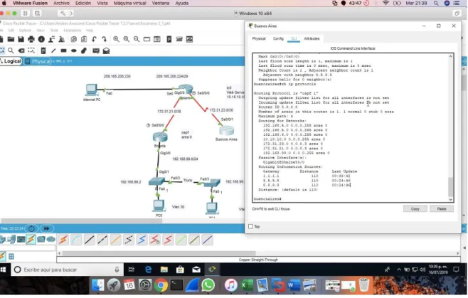
10.3.3 Visualizar el OSPF Process ID, Router ID, Address summarizations, Routing Networks, and passive interfaces configuradas en cada router.
10.3.4 Configurar VLANs, Puertos troncales, puertos de acceso, encapsulamiento, Inter-VLAN Routing y Seguridad en los Switches acorde a la topología de red establecida.
Tabla de enrutamiento.
Nombre Dirección Mascara
VLAN 30: Administracion 192.168.30.0 255.255.255.0 VLAN 40: Mercadeo 192.168.30.0 255.255.255.0
Administración VLAN 200: 192.168.30.0 255.255.255.0
Bogota go/0.1 192.168.99.1 255.255.255.0 N/A
go/0.30 192.168.30.1 255.255.255.0 N/A
go/0.40 192.168.40.1 255.255.255.0 N/A
go/0.200 192.168.200.1 255.255.255.0 N/A
S1 VLAN 99 192.168.99.2 255.255.255.0 192.168.99.1
S2 VLAN 99 192.168.99.3 255.255.255.0 192.168.99.1
PC-A NIC DHCP
PC-B NIC DHCP
Puertos Asignaciones Red
S1 F0/3 Enlace troncal de 802.1Q N/A
S3 F0/3 Enlace troncal de 802.1Q N/A
S1 F0/24 Enlace troncal de 802.1Q N/A
S1 F0/1 VLAN 30: Administración 192.168.30.0/24
S3 F0/1 VLAN 40: Mercadeo 192.168.40.0/24
s1#configure terminal s1(config)#int f0/3 s1(config-if)#shitch s1(config-if)#swithpo
s1(config-if)#switchport mode trunk
s1(config-if)#switchport trunk native vlan 1 s1(config-if)#int f0/24
s1(config-if)#switchport mode trunk
s1(config-if)#switchport trunk native vlan 1 s1(config-if)#no shu
s1(config-if)#switchport trunk native vlan 1 s1(config-if)#int range f0/1-2, f0/4-24, g0/1-2 s1(config-if-range)#switchport mode access s1(config-if-range)#end
s1#
s1#configure terminal s1(config)#int f0/1 s1(config-if)#
s1(config-if)#switchport access vlan 30 s1(config-if)#int range f0/1-2, f0/4-24, g0/1-2 s1(config-if-range)#shu
s1(config)#int vlan 200 s1(config-if)#
s1(config-if)#ip add 192.168.99.2 255.255.255.0 s1(config-if)#no shu
s1(config-if)#exit s1(config)#end s1#
s1(config-if-range)#
s1(config-if-range)#int range f0/4-23,g0/2 s1(config-if-range)#shu
s1(config-if-range)#exit
s1(config)#int range f0/1-2, f0/4-23,g0/1-2 s1(config-if-range)#switchport mode access s1(config-if-range)#int f0/1
s1(config-if)#switchport mode access
s1(config-if)#switchport mode access vlan 30 s1(config-if)#switchport access vlan 30 s1(config-if)#int range f0/2, f0/4-23,g0/1-2 s1(config-if-range)#shu
s1(config-if-range)#no shu s1(config-if-range)#
s2>enable s2#configure t
Enter configuration commands, one per line. End with CNTL/Z. s2(config)#vlan 30 s2(config-vlan)#name administracion s2(config-vlan)#vlan 40 s2(config-vlan)#name mercadeo s2(config-vlan)#vlan 200 s2(config-vlan)#name mantenimiento s2(config-vlan)#vlan 99 s2(config-vlan)#name LAN_S1_S3 s2(config-vlan)#exit
s2(config)#int vlan 99 s2(config-if)#
%LINK-5-CHANGED: Interface Vlan99, changed state to up
%LINEPROTO-5-UPDOWN: Line protocol on Interface Vlan99, changed state to up ip add 192.168.99.3 255.255.255.0
s2(config-if)#no shu s2(config-if)#exit s2(config)#ip default
s2(config)#ip default-gateway 192.168.40.1 s2(config)#
Puertos trocales
s2#configure ter
Enter configuration commands, one per line. End with CNTL/Z. s2(config)#int f0/3
s2(config-if)#switch
s2(config-if)#switchport mode trunk
s2(config-if)#switchport trunk native vlan 1 s2(config-if)#
Puertos de acceso y seguridad 2(config-if-range)#int f0/1 s2(config-if)#no shu s2(config-if)#
s2(config-if)#switchport mode access s2(config-if)#switchport access vlan 40 s2(config-if)#exit
s2(config)#
802.1Q en R1 con los siguientes comandos:
bogota>enable bogota#configure ter
Enter configuration commands, one per line. End with CNTL/Z. bogota(config)#int f0/1/0.30
%Cannot create sub-interface bogota(config)#int g0/0.30 bogota(config-subif)#
bogota(config-subif)#description administracion bogota(config-subif)#encapsul
bogota(config-subif)#encapsulation dot1 bogota(config-subif)#encapsulation dot1Q 30
bogota(config-subif)#ip add 192.168.30.1 255.255.255.0 bogota(config-subif)#exit
bogota(config)#int g0/0.40 bogota(config-subif)#
bogota(config-subif)#description mercadeo bogota(config-subif)#encapsulation dot1Q 40
bogota(config-subif)#ip add 192.168.40.1 255.255.255.0 bogota(config-subif)#exit
En la anterior grafica se analiza que todos los puntos interconectan de manera correcta porque los puntos en las conexiones son de color verde, además de unas pruebas de ping que fueron satisfactorias.
10.3.5 En el Switch 3 deshabilitar DNS lookup
s2>enable s2#configure ter
Enter configuration commands, one per line. End with CNTL/Z. s2(config)#no ip do
s2(config)#no ip domain
s2(config)#no ip domain-lookup s2(config)#exi
10.3.6 Asignar direcciones IP a los Switches acorde a los lineamientos.
s1#sh ip interface
Vlan1 is up, line protocol is up
Internet address is 192.168.99.2/24 Broadcast address is 255.255.255.255 s2#sh ip interface
Vlan1 is up, line protocol is up
10.3.7 Desactivar todas las interfaces que no sean utilizadas en el esquema de red.
Interfaces desactivas en ateriores pasos
10.3.8 Implement DHCP and NAT for IPv4
bogota>enable
bogota#configure termina
Enter configuration commands, one per line. End with CNTL/Z. bogota(config)#ip dhcp pool administrador
bogota(dhcp-config)#dns-server 10.10.10.11 bogota(dhcp-config)#ip dhcp pool administracion bogota(dhcp-config)#default-router 192.168.30.1
bogota(dhcp-config)#network 192.168.30.0 255.255.255.0 bogota(dhcp-config)#exit
bogota(config)#ip dhcp pool mercadeo bogota(dhcp-config)#dns-server 10.10.10.11
bogota(dhcp-config)#network 192.168.40.0 255.255.255.0 bogota(dhcp-config)#default-
bogota(dhcp-config)#default-router 192.168.40.1 bogota(dhcp-config)#exit
Nat
miami(config)#access-list 1 permit 192.168.30.0 0.0.0.255 miami(config)#access-list 1 permit 192.168.40.0 0.0.0.255 miami(config)#access-list 1 permit 192.168.4.0 0.0.3.255
miami(config)#ip nat pool Internet 209.165.200.225 209.165.200.228 netmask 255.255.255.248
miami(config)#ip nat inside source list 1 pool Internet
miami(config)#ip nat inside source static 10.10.10.10 209.165.200.229 miami(config)#int f0/0
%Invalid interface type and number miami(config)#int g0/0
miami(config-if)#ip nat outside miami(config-if)#int f0/0
%Invalid interface type and number miami(config)#int g0/1
miami(config-if)#ip nat inside miami(config-if)#exit
miami#
10.3.9 Reservar las primeras 30 direcciones IP de las VLAN 30 y 40 para configuraciones estáticas.
bogota>enable
bogota#configure terminal
Enter configuration commands, one per line. End with CNTL/Z. bogota(config)#ip dhcp excl
bogota(config)#ip dhcp excluded-address 192.168.30.1 192.168.30.30 bogota(config)#ip dhcp excluded-address 192.168.40.1 192.168.40.30 bogota(config)#
Configurar DHCP pool para VLAN 30
Name: ADMINISTRACION DNS-Server: 10.10.10.11
Domain-Name: ccna-unad.com Establecer default gateway. Name: MERCADEO
Configurar DHCP pool para VLAN DNS-Server: 10.10.10.11
40 Domain-Name: ccna-unad.com
Establecer default gateway.
10.3.10 Configurar NAT en R2 para permitir que los host puedan salir a internet
miami>enable miami#configure ter
Enter configuration commands, one per line. End with CNTL/Z. miami(config)#ip acces
miami(config)#ip access-list standar miami(config)#ip access-list standard 1 miami(config-std-nacl)#permi 172.31.0.0 miami(config-std-nacl)#permi
miami(config-std-nacl)#permit 172.31.0.0 0.0.0.3 miami(config-std-nacl)#exit
miami(config-if)#ip nat ouside miami(config-if)#ip nat ouside
^
% Invalid input detected at '^' marker.
miami(config-if)#ip nat outside
miami(config-if)#ip nat inside source list 1 pool internet
miami(config)#ip nat pool internet 209.165.200.224 209.165.200.229 netmask 255.255.255.248
miami(config)#end miami#
10.3.11 Configurar al menos dos listas de acceso de tipo estándar a su criterio en para restringir o permitir tráfico desde R1 o R3 hacia R2.
bogota(config)#access-list 1 permit
bogota(config)#access-list 1 permit 192.168.30.0 0.0.0.255 bogota(config)#access-list 1 permit 192.168.40.0 0.0.0.255
bogota(config)#ip nat pool internet 209.165.200.224 200.165.200.228
10.3.12 Configurar al menos dos listas de acceso de tipo extendido o nombradas a su criterio en para restringir o permitir tráfico desde R1 o R3 hacia R2.
11. CONCLUSIONES
Del siguiente informe podemos concluir:
Las redes generalmente utilizan una combinación de routing estático y dinámico. El routing dinámico es la mejor opción para las redes grandes, y el routing estático es más adecuado para las redes de rutas internas.
NAT conserva el espacio de direcciones públicas y reduce la sobrecarga administrativa de forma considerable al administrar las adiciones, los movimientos y las modificaciones. NAT y PAT se pueden implementar para conservar espacio de direcciones públicas sin afectar la conexión al ISP. Sin embargo, NAT presenta desventajas en términos de sus efectos negativos en el rendimiento de los dispositivos, la movilidad y la conectividad de extremo a extremo, y se debe considerar como una implementación a corto plazo para el agotamiento de direcciones, cuya solución a largo plazo es IPv6.
Todos los nodos en una red requieren una dirección IP única que se comunique con otros dispositivos. La asignación estática de información de direccionamiento IP en una red grande produce una carga administrativa que puede eliminarse mediante el uso de DHCPv4 y DHCPv6 para asignar de forma dinámica información de direccionamiento IPv4 e IPv6, respectivamente.
El filtrado de paquetes controla el acceso a una red mediante el análisis de los paquetes entrantes y salientes y la transferencia o el descarte de estos según criterios como la dirección IP de origen, la dirección IP de destino y el protocolo incluido en el paquete. Un router que filtra paquetes utiliza reglas para determinar si permite o deniega el tráfico. Un router también puede realizar el filtrado de paquetes en la capa 4, la capa de transporte.
12. BIBLIOGRAFÍA O REFERENCIAS
CISCO. (2014). Enrutamiento Dinámico. Principios de Enrutamiento y
Conmutación. Recuperado de
https://static-course-
assets.s3.amazonaws.com/RSE50ES/module7/index.ht
ml#7.0.1.1
Macfarlane, J. (2014). Network Routing Basics : Understanding IP Routing in
Cisco Systems. Recuperado
de
http://bibliotecavirtual.unad.edu.co:2048/login?url=
http://search.ebscohost.com/login.aspx?direct=true&db
=e000xww&AN=158227&lang=es&site=ehost-live
Lucas, M. (2009). Cisco Routers for the Desperate : Router and Switch Management, the Easy Way. San Francisco: No Starch Press. Recuperado
de
https://1drv.ms/b/s!AmIJYei-
NT1Im3L74BZ3bpMiXRx0
Odom, W. (2013). CISCO Press (Ed). CCNA ICND1 Official Exam Certification
Guide. Recuperado
de
http://ptgmedia.pearsoncmg.com/images/97815872
05804/samplepages/9781587205804.pdf
Odom, W. (2013). CISCO Press (Ed). CCNA ICND2 Official Exam Certification
Guide. Recuperado
de
http://een.iust.ac.ir/profs/Beheshti/Computer%20ne
tworking/Auxilary%20materials/Cisco-ICND2.pdf
CISCO. (2014). Listas de control de acceso. Principios de Enrutamiento y
Conmutación. Recuperado de
https://static-course-
ANEXOS
Anexo A. Los anexos
https://unadvirtualedu-