Reflectarray to Generate Four Adjacent Beams per Feed for Multi-Spot
Satellite Antennas
Daniel Martinez-de-Rioja Eduardo Martinez-de-Rioja
Jose A. Encinar Rafael Florencio, and Giovanni Toso
Abstract—This contribution describes a design concept of a
reflectarray antenna to produce four adjacent beams per feed through the simultaneous use of polarization and frequency discrimination The feed position is computed to produce two adjacent beams in different frequencies accounting for the beam squint effect, which ensures a minimum phase variation between the phase distributions at the two frequencies. The other two beams in orthogonal polarization are generated by implementing in the reflectarray a different phase-shift for each polarization. This contribution presents the design, manufacturing and measurement of a 43-cm demonstrator that operates at transmit frequencies in Ka-band. The proposed concept can be suitable for multiple spot beam satellites in Ka-band, enabling a reduction in the number of antennas and feeds needed to provide the multi-spot coverage.
Index Terms—Reflectarray, beam squint, coupled dipoles, multibeam antennas, satellite antennas.
I. INTRODUCTION
The existing High Throughput Satellites (HTS) in Ka-band produce between 50 and 100 overlapping spot beams with a four color frequency and polarization reuse scheme [1]. The conventional reflectors employed on board the satellite cannot provide closely spaced beams (around 0.56° separation) and typically four reflectors operating in transmission (Tx) and reception (Rx) are required to generate a four-color coverage (using two frequencies and two polarizations) with overlapping spots, one reflector per color.
Different attempts have been made to generate a multiple spot-beam coverage with a single aperture [2], using direct radiating arrays (penalized by high complexity and cost) [3], [4], or a single oversized shaped reflector of 4.5-m diameter [5]. Recent works have proposed the use of reflectarray antennas [6] to reduce the number of apertures by generating two different colors per feed, either in two polarizations [7] or in two frequencies [8]. Reflectarray antennas operating at multiple frequencies have been widely studied when the frequency bands are relatively close [9]-[ll], but some of the previous works do not allow to implement an independent phase control in each polarization, as in [10], where the symmetry of the printed elements prevents achieving this feature.
Recently, beam squint effect in offset reflectarray antennas [12] was exploited to generate two adjacent beams per feed at two relatively close frequencies (19.5 and 20.0 GHz) [8], although with heavy restrictions in the operational bandwidth of the system. In this paper, the authors propose a reflectarray antenna which is able to generate four adjacent beams per feed in two closely spaced frequency bands and two polarizations (four colors) for a multi-spot coverage for Tx in Ka-band, considering the current tendency towards changing the gateway link to Q/V band [13], what enables the use of frequencies between 17 and 20 GHz for the users' link. A 43-cm reflectarray demonstrator has been designed, manufactured and tested. After computing the feed position to determine the direction of each beam based on the beam squint effect, four different phase distributions (one for each color) are obtained, in order to provide four adjacent beams per feed. Then, the reflectarray elements are designed to ensure the required phase in the prescribed frequency bands at both polarizations, as in [14]. The results demonstrate for first time that four adjacent beams, in different frequency and polarization, can be achieved with a single feed.
II. DESIGN TECHNIQUE TO PRODUCE FOUR ADJACENT BEAMS PER FEED
A reflectarray antenna designed to radiate a pencil beam in the direction {6bi, (34i) at frequency fix produces a certain plane wave-front. The phase introduced by each reflectarray cell to generate a plane wave-front associated to {8b, <pb) can be obtained as [6]:
0O;.y¡) = ko(dt - {XiC0S(p„ + yiSin(pb)sin0b) (1)
where d¡ is the distance from the phase center of the feed to the cell "z" placed at coordinates {x¡, y¡) with respect to the geometrical center of the reflectarray.
The beam direction is intended to be modified when the reflectarray is illuminated by the same feed at a different frequency, fii, relatively close to/i {fi =fix + A/). The original spatial phase delays will change due to the variation in frequency, producing a new plane wave-front associated to the direction (#42, (342), see Fig. 1. If the formulation is particularized to the xz-plane ((341= (342=0), the equality of the phase delays produced by the path length associated to the elements placed in the extremes of the reflectarray is presented in (2) and (3) at frequencies fix and fii, respectively. Note that d'/ip.) = D-sin{6bi(i)\ where D is the diameter of the reflectarray. The relation between the directions 6b 1 and #42 and the distances d\ and di can be obtained by subtracting the phase delays associated to each frequency, shown in (2) and (3). This relation is presented in (4) and can be used to compute the feed position from the values of d\ and di, so that the reflectarray is able to generate two beams in the directions 6bi and 0b2 at two frequencies/! and/2 with a unique feed and phase distribution in the reflectarray antenna.
(feo + A f eo) - ( d1+ d '/ 2) + 0 ( - ^ , O ) =
(feo+Afe0)-d2 + 0 ( ^ , 0 ) (3)
d2 = di + D • sin{6b2) + ^D[sin(8b2) - sin(8bl)] (4)
Fig. 1. Reflectarray to generate two beams at two frequencies.
The use of a single phase distribution (as in [8]) forces to consider close operating frequencies in order to avoid beams significantly distorted, but this strategy has the drawback of producing a continuous variation of the beam direction with frequency. In this paper, the authors propose to use more separated operating frequencies to obtain a larger bandwidth, since the next generation of HTS systems is expected to use the frequencies between 17 and 20 GHz for the users' link in Ka-band [13]. The use of relatively distant frequencies restrains the possibility of implementing the same phase distribution in the reflectarray for both frequencies, due to beam distortion. Then, the reflectarray elements will be optimized to provide a slightly different phase distribution at each frequency as in [14]. This optimization will also minimize the beam deviation within each frequency band. To ensure a minimum phase variation between the phase distributions at fi and fi, the feed position must be computed by (4); otherwise, the maximum difference between the phases at each frequency for a similar reflectarray with the feed placed in the specular direction of the radiated beam will be around five times larger than in the previous case.
The discrimination of the orthogonal polarizations will be performed through the use of appropriate reflectarray cells based on orthogonal sets of stacked parallel dipoles (see Section III). These cells allow independent control of the phase in each linear polarization (LP), enabling the implementation of two different phase distributions on the reflectarray. Although the beams are generated in orthogonal LP, the variable rotation technique (VRT) of the elements can be used to generate the adjacent beams in dual-circular polarization [7].
Dual polarized feed-horns are assumed to illuminate the antenna, so that each feed will produce two adjacent beams in orthogonal polarizations at each design frequency. A simple way of obtaining the phase distribution for the second orthogonal polarization to generate the beams in a 60° lattice with respect to the xz-plane is by adding a progressive phase term to the original phase distribution. The required phase increment A<j> at each reflectarray cell can be obtained using (5), where («41, VM) and (ub2, vbi) are the directions of maximum radiation in each polarization in the normalized angular coordinates m = sin Ob • cos q>b, vb = sin Ob • sin q>b.
A0(x¡,y¡) = -k0[(ubl - ub2)xt + (vbl - vb2)yt] (5)
As a consequence of the design process, four different phase distributions will be implemented on the reflectarray, one for each frequency and polarization combination (same color).
III. DESIGN O F A FOUR-BEAM ANTENNA DEMONSTRATOR
A 4 3-cm reflectarray antenna has been designed, manufactured, and measured with the objective of demonstrating the possibility of generating four beams, in four different colors, with a single reflectarray using one dual-polarized feed-horn. The central operating frequencies are 18 GHz and 20 GHz, which have been chosen to allow a relatively large separation between the two frequency bands.
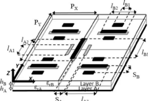
A. Definition and Characterization of the Reflectarray Cell The reflectarray cell used for the design of the demonstrator consists of two dielectric layers and two levels of metallization. The cell comprises two sets of coupled parallel dipoles for controlling each LP. Each set is composed of three coplanar parallel dipoles printed on a dielectric layer and a fourth parallel dipole stacked with the central one and printed on the opposite side of the same dielectric sheet (see Fig. 2). The lateral dipoles of each arrangement are symmetrical with respect to the central one, in order to keep low levels of cross-polarization. A similar reflectarray cell has been previously used in [15] for the design of a Ku-band Tx/Rx reflectarray demonstrator. In this case, the geometrical parameters of the cell have been adjusted to allow simultaneous operation at 18 and 20 GHz, considering 600 MHz bandwidth around each frequency.
Fig. 2. Two-layer reflectarray cells based on orthogonal sets of stacked parallel dipoles.
A different period is set for the cell dimensions along x-axis (Px = 7.5 mm) and^-axis (PY = 8.5 mm), both values close to 1/2. These values have been adjusted to minimize cross-polarization components and avoid the appearance of grating lobes at the higher operation frequency (20.3 GHz) for incidence angles up to 47.8°. Concerning the dipole dimensions, their width is w = 0.4 mm, the separations between laterally coupled dipoles in each layer are SA = 2.3 mm and SB = 2 mm (from center to center), and the relative lengths of the dipoles referred to /B2, which corresponds to the length of the central dipole for X-polarization (X-Pol.) on the top layer, are: /AI = 0.68-&2, /A2 = 1.097B2, /A3 = Im, hi = O.Ti-lm, and hi = 1.09-&2. These parameters were fixed after a careful parametric study of the cell, seeking for a linear behavior of the phase response and a sufficiently large margin of phases at both design frequencies. The lower substrate (layer A) is DiClad 880B with thickness AA = 1.524 mm. The measured values of the dielectric at 20 GHz (EM = 2.3, tanÓA = 0.005) have been used instead of the nominal values at 10 GHz (EM = 2.17, tanÓA = 0.0009) provided by the manufacturer. The upper dielectric (layer B) is CuClad 233 LX, with fe = 0.787 mm, srB= 2.33
and tanSB = 0.0013.
In order to characterize the proposed reflectarray cell, the reflection coefficients related to each LP have been computed at different frequencies in both upper and lower bands. The element phase response has been also studied under different angles of incidence, considering the extreme angles of incidence for the
antenna configuration described in next subsection (0 < 6 < 35°, -45° < <p < 45°). The results show a stable behavior in both frequency bands, with a maximum phase variation of 30° in the worst case. Fig 3 shows the results for the phase of the reflection coefficient for X-Pol. at 18 and 20 GHz versus the lengths of the dipoles, considering normal incidence and oblique incidence associated to one of the reflectarray edges. The graphics indicate the value of lm, since the rest of dipole lengths are referred to lm. As can be seen, the phase shows a smooth variation in a range close to 800° at both frequencies. The module of the reflection coefficient (not shown) presents a maximum level of losses of 0.6 dB. The reflection coefficients present a similar performance for both polarizations at both frequency bands.
ro-200
[16]). The illumination levels on the reflectarray edges are -12 dB at 18 GHz, and -18 dB at 20 GHz. -400
I
600 -800 5 5.5 lB 2 (mm)Fig. 3. Phase of the cell reflection coefficient vs dipole lengths for X-Pol. B. Design Process of the 43-cm Demonstrator
The demonstrator consists on a circular reflectarray with 2,242 elements arranged in a 57 x 50 grid (42.75 cm x 42.5 cm). According to (4), when the increment of frequency (A/) is relatively small and the beam angular separation is relatively large (2.55° for D = 43 cm), the resulting difference in the distances from the feed to the extremes of the reflectarray (di and di) can be large, requiring a position of the feed far away from z-axis that would produce larger angles of incidence on the reflectarray elements. To avoid this fact, the feed has been located in the xz-plane on the same side were the beams are radiated (x > 0), so that di < d\ and 8bi < 6bi, like a retro-directive antenna (despite this fact, it has been checked that the feed does not produce blockage). In this case, the angles of incidence are smaller (0 < 6i < 35°, -45° < f¡ < 45°), providing a better performance of the reflectarray cells and simplifying the design of the demonstrator.
0.6 0.4 0.2 (1 A k.
|
/
|
/
,
/
/
/
L/
1 Reflei*
r 1 -Radiation (0.45°) Radiation (3°) tarray -0.2 0 0.2 0.4 0.6 X [ m ]Fig. 4. Schematic representation of the reflectarray demonstrator.
The antenna is illuminated by a 60-mm feed-horn, whose phase center is placed at coordinates (XF,JT, ZF) = (281.6, 0, 631.1) mm with respect to the reflectarray center (see Fig. 4). The separation between adjacent beams has been set to 2.55°, a value close to the 3dB-beamwidth. The field radiated by the horn has been modeled using a cosi(6>) distribution with q = 31 at 18 GHz, and q = 45 at 20 GHz, according to the information provided by the manufacturer (Anteral
TABLE I
DIRECTIONS OF THE RADIATED BEAMS
Frequency 18.0 GHz 20.0 GHz X-Pol 3.0°, 0.45° (0,9) 0.0° ,0.0° Y-Pol 2.9° 2.55° (0,<P) 52° 108° The antenna has been designed to produce four focused beams in the directions given in Table I. The required phase distributions to be implemented on the reflectarray for X- and Y- Pols, at 18 and 20 GHz have been calculated according to the procedure described in Section II. The dipole lengths are optimized, element by element, to match simultaneously the phase distributions for each polarization at the central and extreme frequencies in both lower (17.7-18.3 GHz) and upper (19.7-20.3 GHz) operating bands, similarly as in [14], by iteratively calling a home-made analysis routine based on the Method of Moments in the Spectral Domain (SD-MoM) and the local periodicity approach [17]. The horizontal and vertical dipoles in both layers are separately adjusted to match the required phases for each polarization. As a result of the optimization, the difference between the achieved and the required phases at 18 and 20 GHz is lower than 20° in most of the reflectarray cells for both polarizations.
The simulated contour patterns in («, v) coordinates at -4 dB with respect to the maximum gain for the four beams generated in X- and Y- Pols, at the central and extreme frequencies of each band are presented in Fig. 5. The beams in the same 'v = constant' plane are generated in different frequencies, while in the other direction, forming 60° with the previous one, the beams are generated in different polarization. The gain levels of the simulated contours are between 32.1 and 33.2 dBi for the four beams.
0.08 0.06 0.04 > 0.02 -0.02 -0.04 if; 111
1
\ \ \v
\ \ V /J\ \ \
' 1 • ijiI •
' I ' -ll.-I J ;
Vs
/ / / ¡JCS. is*''' ^—18.0GHz,X-Pol 18.3 GHz, X-Pol ^ — 1 8 . 0 GHz, Y-Pol 18.3 GHz, Y-Pol ^ — 2 0 . 0 GHz, X-Pol 20.3 GHz, X-Pol — 20.0 GHz, Y-Pol • -20.3 GHz, Y-Pol -0.05 0.05Fig. 5. Simulated -4 dB contour patterns for the four beams.
IV. MANUFACTURE AND MEASUREMENTS OF THE REFLECTARRAY DEMONSTRATOR
The 43-cm reflectarray demonstrator has been manufactured and tested. The two layers of dipole arrays are produced by conventional chemical photo-etching on both faces of the 0.787-mm CuClad 233 LX substrate cladded with 17-um copper. Then, the two dielectric sheets, the 0.787-mm CuClad 233 LX and a 1.524-mm DiClad 880B with copper ground plane on the opposite side, have been bonded by using two layers of thermoplastic film (CuClad 6250). The antenna has been tested in a spherical near-field range at the anechoic chamber of the Universidad Politécnica de Madrid (see Fig. 6).
The measured radiation patterns in 'v = constant' planes at the central and extreme frequencies of each band are shown in Fig. 7 for the beams in X-Pol. ('v = 0' plane), showing very similar behavior in the 'v = 0.04' plane for the beams in Y-Pol. The patterns are very similar for all the frequencies in the same sub-band, with small
deviations in the beam direction of ±0.3°. The highest side lobes in the co-polar patterns are located in the plane 'v = 0' for the beams in X-Pol. and in the plane 'v = 0.04' for the beams in Y-Pol. (the same plane as the main beam), their levels are between 15 and 19 dBi (15 dB below the maximum), and they are produced by the specular reflection of the radiation pattern of the horn.
computed considering the corrected values of SrB and tanSB, achieving a better agreement between measurements and simulations (see Fig. 8). The remaining discrepancies can be attributed to the specular reflection of the radiation pattern of the feed-horn (partially accounted in the simulations), a simplistic cosq(é>) model of the
feed-horn and uncertainty errors in the antenna gain (±0.5 dB).
Fig. 6. Picture of the reflectarray demonstrator in the anechoic chamber.
30 ™ 2 0 CO O 10 ."i If
u
ntfrlt
¿til
j a l l1í
Vr
7^*
A V/*JV J 1 y lÜ
f
J«I'I «i \Fie
\
1
1
V
•ftw
I'l
I WSE 19.7 GHz 20 GHz -20.3 GHz 17.7 GHz 18 GHz 18.3 GHz •» rt Jfc». X ^ v¡n/uwv^
vjljki
\ I
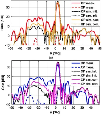
-30 -20 -10 0 1 [deg] 10 20 Fig. 7. Measured radiation patterns at the central and extreme frequencies of each band for the beams in X-Pol. in the plane 'v = 0'.The comparison between the measured and simulated radiation patterns at 18 GHz is presented in Fig. 8. This figure includes an initial simulation considering the values of SrB and tanSB used for the design, and a corrected simulation. The measured main beams are in good agreement with the initial simulations and the levels of cross-polarization are about 26 dB below the co-polar maximum, close to simulated predictions (28 dB). There is a reduction in gain of around 2-3 dB with respect to the initial simulation (36 dBi at 18 GHz and 37 dBi at 20 GHz, for both polarizations). Also, it can be observed that the side lobes corresponding to the specular direction of the feed [0 = -24°) present a higher level in measurements than in simulations. The increase in the side lobes and the reduction in gain are mostly attributed to phase errors produced by the manufacturing tolerances and discrepancies in the electrical properties of the materials. In contrast with the lower substrate (DiClad 880B used in layer A), the material used in the upper layer was not previously characterized and the nominal values (SrB =2.33, tanSB = 0.0013) provided by the manufacturer at 10 GHz were used in the design and simulations.
To check the phase-shift and dissipative losses of the reflectarray cell, two samples have been manufactured and measured in a waveguide simulator (WGS), which is a well-known technique used to measure the performance of array elements in a periodic environment [18]. Two periodic cells have been inserted in short section of WR-51. The values of tanSB and SrB in the upper dielectric layer have been adjusted to SrB = 2.26 and tanSB = 0.0054, in order to have good agreement between measured and simulated values of phase-shift and losses in the WGS. The radiation patterns have been
CP meas. XP meas. CP sim. init. XP sim. init. CP sim. corr. XP sim. corr. -50 -40 -30 - 2 0 - 1 0 0 10 20 30 40 50 6 [deg] -50 -40 -30 - 2 0 - 1 0 0 10 20 30 40 6» [deg] (b)
Fig. 8. Measured and simulated radiation patterns at 18 GHz: (a) for X-pol in the plane 'v = 0', and (b) for Y-pol in the plane 'v = 0.04'.
0 06 0.04 > 0.02 0 -0.02
/
*7&
It// VI' til if/ ill tJU* IX
1 I \\ v •-,
; i\
\
\
Y i 1 t Ji
4 <-•• i t /}
0.05 0.1Fig. 9. Measured -4 dB contour patterns at the lower, central and upper frequency of each band (dotted, solid and dashed lines) including the simulated -4 dB contours at the central frequencies.
The measured contour patterns at -4 dB with respect to the maximum gain for the four colors at central and extreme frequencies of each band (17.7-18.3 GHz and 19.7-20.3 GHz) are shown in Fig. 9. These levels represent the minimum gain in the coverage. Despite that the contours of the measured beams are slightly distorted, the results show for first time that the reflectarray demonstrator is able to produce four adjacent beams in two frequencies and two polarizations using a single feed. The simulated -4dB contours (for the corrected values of SrB and tanSB) are also included in the figure (black lines), showing a good agreement with the measurements. The levels of the measured contours are between 29 dBi (X-Pol. at 18 GHz) and 31.7 dBi (X-Pol. at 20 GHz).
V. CONCLUSION
A technique has been proposed to design a reflectarray antenna capable of producing four closely spaced beams, in different frequency and polarization, for each feed. The feed position has been computed to produce two adjacent beams in different frequencies by exploiting the beam squint effect, ensuring a minimum phase variation between the phase distributions at the two frequencies. The other two beams are generated in the orthogonal polarization by implementing in the reflectarray a different phase-shift for each polarization.
A 43-cm reflectarray has been designed, manufactured and tested to demonstrate for first time that a reflectarray can generate four adjacent beams in different polarization and frequency (4 colors) with a single feed. The results have satisfactorily validated the proposed concept and the design technique, whose application to multi-beam satellite antennas will be further investigated in the future, as it allows a reduction in the number of feeds and antennas required when using conventional reflectors. The four reflectors operating in Tx and Rx could be reduced to two reflectarrays, one for Tx and other for Rx, producing a significant mass saving on the spacecraft.
REFERENCES
[I] M. Schneider, C. Hartwanger and H. Wolf, "Antennas for multiple spot beams satellites", CEAS Space Journal, Vol. 2, pp. 59-66, Dec. 2011. [2] G. Toso, C. Mangenot and P. Angeletti, "Recent advances on space
multibeam antennas based on a single aperture", 2013 7th European Conference on Antennas and Propagation (EuCAP), Gothenburg, 2013, pp. 454-458.
[3] O. Kilic and A. I. Zaghloul, "Antenna aperture size reduction using subbeam concept in multiple spot beam cellular satellite systems", in Radio Science, vol. 44, no. 3, pp. 1-9, June 2009.
[4] G. Toso, P. Angeletti and C. Mangenot, "Multibeam antennas based on phased arrays: An overview on recent ESA developments", The 8th European Conference on Antennas and Propagation (EuCAP), The Hague, 2014, pp. 178-181.
[5] P. Balling, C. Mangenot and A. G. Roederer, "Shaped single-feed-per-beam multisingle-feed-per-beam reflector antenna", Is' European Conference on
Antennas and Propagation, Nice, France, 6-10 Nov. 2006.
[6] J. Huang and J. A. Encinar, "Reflectarray Antennas", IEEE Press/Wiley, Piscataway, New Jersey, 2008
[7] M. Zhou and S. B. Sorensen, "Multi-spot beam reflectarrays for satellite telecommunication applications in Ka-band", 10th European Conference on Antennas and Propagation (EuCAP), Davos, 2016, pp.1-5.
[8] D. Martinez-de-Rioja, E. Martinez-de-Rioja, and J. A. Encinar, "Multibeam reflectarray for transmit Satellite antennas in Ka band using beam-squint", in Proc. IEEE Int. Symp. Antennas Propag., Fajardo, PR, USA, Jul. 2016, pp. 1421-1422.
[9] M. R. Chaharmir, J. Shaker, N. Gagnon and D. Lee, "Design of broadband single layer dual-band large reflectarray using multi open loop elements", IEEE Trans. Antennas Propag., vol. 58, no. 9, pp. 2875-2883, September 2010.
[10] H. Hasani, C. Peixeiro, A. Skrivervik and J. Perruisseau-Carrier, "Single-layer quad-band printed reflectarray antenna with dual linear polarization", IEEE Trans. Antennas Propag., vol. 63, no. 12, pp. 5522-5528, December 2015.
[II] J. A. Encinar, M. Arrebola, L. F. de la Fuente, G. Toso, "A transmit -receive reflectarray antenna for direct broadcast satellite applications", IEEE Trans, on Antennas &Propag., vol. 59, pp.3255-3264, Sep. 2011. [12] S. D. Targonski and D. M. Pozar, "Minimization of Beam Squint in
Microstrip Reflectarrays Using an Offset Feed," IEEE Antennas and Propagation Soc. International Symposium, pp. 1326-1329, July 1996. [13] B. Palacin, N. J. G. Fonseca, M. Romier, R. Confreres, J. C. Angevain,
G. Toso and C. Mangenot, "Multibeam antennas for very high throughput satellites in Europe: Technologies and trends", in Proc. 11th Eur. Conf. Antennas Propag. (EuCAP), Paris, France, April 2017, pp. 2413-2417.
[14] J. A. Encinar, R. Florencio, M. Arrebola, M. A. Salas, M. Barba, R. R. Boix, G. Toso , "Dual-Polarization Reflectarray in Ku-band Based on
Two Layers of Dipole-Arrays for a Transmit-Receive Satellite Antenna with South American Coverage", International Journal of Microwave and Wireless Technologies, pp. 1-11, Feb. 2018.
[15] R. Florencio, J. A. Encinar, R. R. Boix, V. Losada, and G. Toso, "Reflectarray Antennas for Dual Polarization and Broadband Telecom Satellite Applications", IEEE Trans, on Antennas &Propag., vol. 63, no. 4, pp. 1234-1246, April 2015
[16] https://anteral.com/en/products/antennas/spline-horns
[17] R. Florencio, R. R. Boix, E. Carrasco, J. A. Encinar and V. Losada, "Efficient numerical tool for the analysis and design of reflectarrays based on cells with three parallel dipoles", Microw. Opt. Technol. Lett., vol. 55, no. 6, pp. 1212- 1216, June 2013.
[18] P. W. Hannan, M. A. Balfour, "Simulation of phased array antennas in waveguides''', IEEE Trans, on Antennas Propagat., Vol. 13, pp. 342-353, May 1965.