1 INTRODUCTION
The Cordoba`s mosque tower, that gives access to the orange trees patio, houses in its core the old minaret dating from 946 AD, on which is superimposed, as a shell, the current bell tower built in 1523.
In order to characterize the foundations of both buildings and the underlying soil, and analyze the stability of the whole, an investigation was performed, consisting in a geotechnical testing campaign and a series of calculations by both traditional numerical and finite elements methods.
The results displayed in this paper, pretend to expand the knowledge about historical build-ings of our cities, and to enable to undertake conservation works with major rigor and effective-ness.
2 METHODOLOGY
In the surroundings of the tower seven drill bores tests were performed, 2 vertical and five in-clined (4 to 10º and 1 to 65º) that allowed analyzing the soil stratigraphy as well as the founda-tion composifounda-tion, and nine dynamic soundings.
From the drill bores some samples of soil and foundation were extracted and water from the groundwater table. To identify and characterize the samples the following tests were performed in laboratory.
To the soil samples:
Classification by size, Atteberg limits and natural moisture. Bearing capacity: simple compression and direct shear.
Strain: determination of the one-dimensional consolidation by oedometric test, swel-ling, free swelling pressure and collapse.
Determination of the aggressiveness of groundwater and soils, through chemical analysis (organic matter, sulfates, chlorides, nitrates, nitrites….).
STUDY OF THE FOUNDATIONS OF CORDOBA’S MOSQUE
TOWER
To the samples from foundation, Stone masonry, lime concrete and bricks: Chemical components, dosage.
Physical Properties: Density, porosity, absorption. Mechanical properties: compressive strength.
From the data obtained by geotechnical campaign and the tests performed, we proceed to cal-culate settlement of foundations occurred in both phases of its construction: the first one that corresponds to the Muslim minaret built in 946, and the second one, the Christian cladding from 1523 the construction of the Bell Tower, that increased the height and the weight.
To analyze the stability, two different methods were used, the traditional one (analytical cal-culation by Steinbrenner) and a finite element method with Plaxis software.
3 STRATIGRAPHY
Once analyzed the samples, five geotechnical levels were established. Here we describe each level, the stratigraphy, the depth and size, as well as the composition and characteristics.
Level 1: Infill soil, the outer soil layer of the Ablutions Patio, of about 3,7 m depth, bigger as closer to the tower. Under the pavement of the courtyard, sand-clay soils alternating with other silt-clay (SC-SM) brownish color, were found, with many ceramic and stone remains corres-ponding to the different archaeological levels in this area, at a rate of close to 50% of the ma-terial extracted from the samples.
Dynamic soundings performed close to the tower show a low compactness till a depth of 7 meters underneath the pavement, were the foundations are laying on. The values obtained reveal an NB of between 3 and 16 strikes.
Level 2: Colluvial and fine alluvial (silt clays) soil. It is a layer of 3,20 m thick appearing from -3,7 m uo to -6,9 m depth, of silt clays medium plasticity (CL), with possible levels of clay silts (CL-ML), including nodules and white veining of carbonates, being the main color brown, or dark grayish brown in the upper soil due to edaphic alteration.
Flood load oedometric tests show soils of moderate to low expansive potential, recording values of free swelling of 0,85 / 1,15%, and swelling pressure of 24,5 to 29,4 kN/m². The value of collapse (extra settlement with humidity increase) is 0,19 / 0,26%, also considered low. Oe-dometric modules measured in the different tests vary between 11,08 and 13,14 MN/m² for in-tervals of 98,1 to 196,1 kN/m². The values of simple compressive strength on unaltered samples have shown values of bearing capacity (qu) between 80.4 and 387,4 kN/m² and an internal fric-tion angle between 21,1 and 23,2º.
This is the level were foundations of the external enclosure corresponding to the walls of the Mosque and the porticoes of the Ablutions Courtyard are lying.
Level 3: medium and fine, alluvial soil. This level corresponds to the height ranging from -6.9 to -8.5m. It predominantly includes granular soils, silty sands (SM) or sandy silts, predomi-nating silty soils in the upper zone. They are light brown, stable soils due to their granular na-ture and the depth in which they appear.
SPT tests show values of N=23-27, equivalent to an average compactness. Strikes corres-ponding to dynamic soundings, yield values between 18 and 40.
Level 4: Coarse alluvial. This layer is detected in the seven sample bores with different thick-nesses, from -8,5m to -14m, in the area of the tower to -7 to -8m in closer to the mosque. These granular soils are a mixtures of gravels and sands (GP, GM and SP), with a smaller amount of silt. The soil is shown partially hardened with conglomerates in some sections. Towards the base, the fraction of stone gravel increases. The excellent geotechnical conditions of this level are the support of the tower foundations.
Level 5: Altered blue marl and consolidated marls of Miocene. They appear at the height of -14 m, and are representative of the Guadalquivir valley soil. They are silt-clay soils (CL, ML) of greenish and bluish hue according to the depth. Its consistency is medium to high, with an aver-age value of oedometric deformation of 12,74 MN/m², and of simple compression 588,4-686,5 kN/m². Long term cohesion values are about 12,7 kN/m² and the friction angle of 20,2°.
4 FOUNDATION
The foundation of the tower is a masonry prism with 8,8 m x 8,0 m floor plan section and an av-erage depth of 7.9 m, from the pavement. The support level corresponds to stratum no. 3 con-sisting of silt sand at the beginning, and gravel with sand stratum (level 4).
The Christian added envelope element has an average thickness of 2,10m in three of the sides of the Tower, and 8m in the fourth. Therefore, the section of the current foundation is 10m x 16,85m.
The materials used to construct this foundation are:
Sandstone ashlar masonry of 15 to 30 cm side, and a density of 18,93 KN/m3, in the foundation of the 10th century; calcarenite stone ashlar masonry of 40 to 50 cm side and a density of 20,89 KN/m3, in the foundations constructed in 16th century.
Lime concrete alternating with stone masonry, to get the flatness of the different courses, with a density of 16,77 kN/m3.
Some remains of bricks in the leveling layers.
5 ANALISYS
5.1 Stability calculation. Stress-strain analysis of the tower foundations by analytical methods.
From the data obtained by geotechnical tests performed, the calculation of the settlement per-formed in both interventions is carried out. The first one, the construction of the Muslim minaret in 946, and the second one, the Christian cladding of 1523 to build the Bell Tower increasing the height of the tower.
5.1.1 First phase: construction of the Minaret.
The floor plan of the Minaret of Abd - al Rahman III is 8,8 x 8,0m and the foundation depth is between 7,7 m and 8,1 m. The average depth value of 7,9m is adopted for calculation purpos-es. Accordingly, the foundation has a volume of 556,16 m3, so considering an average of densi-ty of the constituent naterials of 21,57 kN/m3, the total weight of the foundation is estimated in 11.996,37 kN. Substracting soil weight considering an average density of soil of 18,63 KN/m3, the total weight of the foundation considered is 1.635,11 kN.
The height of the Minaret at the time is considered to be 50 m, the thickness of the walls is estimated at 0,4 m, the section of the tower is of 8.8 x 8 m, and therefore, the weight is 16.318,27 kN; Adding the foundation weight, the total transmitted load is 17.953,38 kN, sup-ported on a surface of 70,4 m², which is equivalent to 255,02 kN/m².
5.1.2 Second phase: the construction of the Bell Tower.
The Christian intervention envelops the Minaret in calcarenite stone ashlars to raise the height of the tower and place the corresponding belfry, changing the floor plan of the tower up to the dimension of 10m x 16,8m (168 m², corresponding 70,4 m² to the ancient Muslim minaret and the remaining 97,6 m² to the Christian construction). This represents an added load of 16,605.6 kN. To this load figure, the excavated soil must be subtracted, which is 14,405.02 kN, so the load increase corresponding to the new foundation is 2,200.58 kN, and the total weight of the foundation 3,904.52 kN.
With these data, it can be established that the 16th century construction could have increased the load up to 42,806.03 kN.
5.1.3 Collapse load of the tower (XVIth century).
To determine the collapse load of the tower, we estimated that the foundation is solid and that it does not exceed the perimeter, so considered that the depth at which it lay son is 7,70 m, and that the tower floor plan dimensions are 10,00 x 16,80 m. In addition the following selection of geotechnical parameters are considered:
Level 1. From 0,00 to 6,40 m, upper fillings of the excavation and clay soils and sand-silt soils (CL, SC, ML, SM):
Cohesion C’ = 0,00 kN/m² Friction internal angle Ø’ = 22º Bulk density γap = 17,65 kN/m3
Level 2. From 6,40 m to 12,30 m, dense sandy gravel with aggregate levels (GP, SP): Cohesion C’ = 0 kN/m3
Friction internal angle Ø’ = 36º Bulk density γap = 20,59 kN/m3 Submerged density γ’ = 10,79 kN/m3
Level 3. From 12,30 m onwards, blue marls (CL, ML): Compressive strength qu= 686,47 kN/m² Cohesion C’ = 12,75 kN/m²
Friction angle Ø’ = 20,2º Bulk density γap = 18,93 kN/m3 The water table is at 11,35 m
5.1.4 Analytical calculation of collapse load and the safety coefficient before the collapse
Applying the Brinch Hansen formula, considering that the vertical component has produced the collapse, by the equation:
Pvh= q Nq Sq iq+C Nc Sc ic+1/2 γB NγSγ iγ Considering:
Q = soil live load at the foundation depth, around the foundation. C = cohesion
γ = soil specific weight
Nq, Nc y Nγ = load capacity coefficients depending on the soil friction angle Sq, Sc, Sγ = shape coefficient
Iq, ic, iγ = inclination coefficient
The collapse load calculated is Pvh= 9,648.37 kN/m2
The safety coefficient before the collapse is calculated dividing the foundation collapse load and the actually transmitted load.
An approximation to the loads transmitted by the tower has been estimated, evaluating 642,04 kN/m² transmitted to the base, and hence, resulting the safety coefficient of 15,02, much higher than the minimum of 3 required, and is clearly acceptable to ensure stability in the long term foundation settlement
5.1.5 Settlement Calculation.
The settlements occurred during the construction of the tower and later were calculated. The calculation method used for the induced settlements produced is the Steinbrenner model, which is a multi-layer model on a rigid layer. It consists on calculating for each layer the settlement at the beginning and at the end of it, obtaining the total settlement as Si = So-Sz; being So= set-tlement at the beginning of the layer; Sz= setset-tlement at the end of the layer.
1 2
2
E
A
B
B
P
Considering:
P = net pressure transmitted by the structure B = foundation width
A = 1-µ
B = 1-µ-2µ², being µ= Poisson coefficient
Ø1 and Ø2 are coefficients depending on the foundation dimensions and the depth of each layer.
E = strain module. It can be estimated from the oedometric tests and the penetration tests. The calculation of settlements is carried out with the following geo-mechanic scheme, based on previous data, and for the oedometric tests, from the current height level (height 0.00):
From 0,00 to 3,70 m recent sand clay fillings, E = 5.393,66 kN/m² From 3,70 m to 6,90 m brown clays, E = 12.454,45 kN/m² From 6,90 m to 8,50 m sands and sand silts, E = 9.806,65 kN/m² From 8,50 m to 14,00 m dense sand gravel, E = 49.033,25 kN/m² Blue marls/Miocene starting at 14,00 m, E = 12.748,65 kN/m²
The average foundation settlement with a parabolic distribution under it is Saverage = Scorn-er + 0,66(ScornScorn-er + ScentScorn-er).
With 10 x 16,80 m dimensions for the floor plan and transmitted stresses of 642,04 kN/m² at a depth of 7,70 m, a settlement of 14,79 cm is calculated.
Probably, and with the existing ground pattern, settlements should have been very uniform given the bearing capacity of the gravel stratum, and largely, about 75%, occurred during the construction process. The remaining 25% should have culminated in the first five years from the construction completion.
5.2 Stability calculation: stress-strain analysis of the Minaret Tower foundations of the mosque of Cordoba by finite elements technique. Model Data.
Carried out with the software of finite elements method (PLAXIS) through the Mohr-Coulomb model to establish the ground behavior, and dividing it into several phases mainly related to the construction milestones outlined in previous sections. The Muslim construction and the later Christian addition have been differentiated, the settlements for each one of them estimated, as well as the safety factor before collapse.
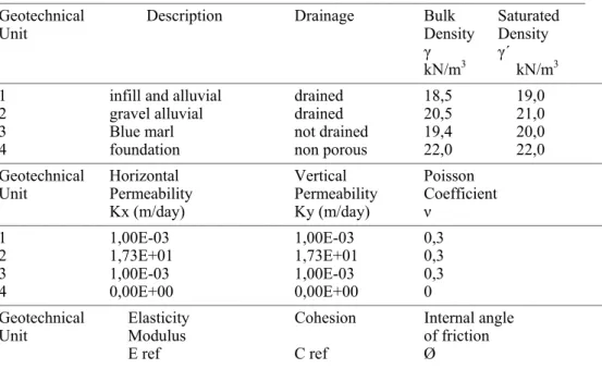
3 different geotechnical units are defined, adding the foundation. Geotechnical data are ex-posed in the following table:
Table 1: Geotechnical parameters
__________________________________________________________________________________________
Geotechnical Description Drainage Bulk Saturated Unit Density Density
γ γ´ kN/m3 kN/m3
_____________________________________________________________________________________________
1 infill and alluvial drained 18,5 19,0 2 gravel alluvial drained 20,5 21,0 3 Blue marl not drained 19,4 20,0 4 foundation non porous 22,0 22,0
_____________________________________________________________________________________________
Geotechnical Horizontal Vertical Poisson Unit Permeability Permeability Coefficient
Kx (m/day) Ky (m/day) ν
_____________________________________________________________________________________________
1 1,00E-03 1,00E-03 0,3
2 1,73E+01 1,73E+01 0,3 3 1,00E-03 1,00E-03 0,3 4 0,00E+00 0,00E+00 0
_____________________________________________________________________________________________
Geotechnical Elasticity Cohesion Internal angle Unit Modulus of friction
kN/m2 kN/m2 (º)
_____________________________________________________________________________________________
1 8000 10 22
2 50000 1 36
3 13000 50 26
4 1,00E+06 50 40
_____________________________________________________________________________________________ Geotechnical Dilatancy Interphase Unit angle Ψ (º) Rinter _________________________________________________________ 1 0 1
2 6 1
3 0 1
4 10 1
_________________________________________________________
The analysis is carried out with two models, firstly, a long term analysis under drained condi-tions is made, and later, a staggered construction is simulated with an analysis of the consolida-tion on the layer of grey marly clays.
5.2.1 First phase. Muslim Construction.
At an average depth of 7,70 m, the foundation transmits a net stress of 23 kN/m² after the origi-nal soil has been removed. The Muslim construction ends with the Minaret, which increases the net transmitted stresses at the base of the foundation up to 260 kN/m², generating the settle-ments of 3,86 cm.
5.2.2 Second Phase. Christian Construction.
The construction of the Christian foundation is modelled first, increasing the floor plan surface of the foundation up to the current value of 10 x 16,85 m, conveying a similar value of 23 kN/m², to the Muslim foundation in this sector attached to the Minaret, and causing strains or maximum settlements of 3,99 cm.
Finally, the construction of the attached element or Christian envelope of the Minaret is con-cluded to raise the height of the Tower, increasing the transmitted stresses to a total of 549 kN/ m², producing a settlement of 13,4 cm.
The safety factors for the collapse load at the end of the of the Muslim and Christian con-struction have been estimated, obtaining a value of 4,02 for the Muslim concon-struction; this factor is reduced to 1,89 in the case of the heavier Christian construction
Then, an analysis of consolidation has been simulated recording interstitial pressures generat-ed, and simulating first the construction of the Muslim foundation in one year; after it, a period of 5 years of the Muslim minaret construction has been simulated --enough to dispel practically all the excesses of interstitial pressure from the marl stratum. More than 5 centuries elapse until the construction of the Christian foundation, which we assume takes one year, culminating the construction of the tower and belfry in other five years.
Total settlements obtained under these conditions are similar to the previous ones, although in this case, the excess pore pressure can be registered in the blue marl stratum.
The safety factors obtained for this assumption of consolidation analysis reach safety coeffi-cients of 4,184 at the end of the Muslim construction; and 3,964 at the conclusion of the Chris-tian construction.
6 CONCLUSIONS
An abstract of the Settlement occurred, and the security factors determined in the phases of the construction are shown in the following table:
Table 2. Settlement and Security Factor determined.
________________________________________________________________________________________
Analytical calculation method
Settlement (cm) Security Factor 14,79 15,02
Finite Elements Method. Long term Drainage.
Phase Settlement Security Factor (cm)
Muslim Foundation 0,37
End of the Muslim Foundation 3,86 4,50 Christian foundation, Envelope 3,99
End of the Christian tower 13,4 2,096
________________________________________________________________________________________
Finite Elements Method. Calculation considering consolidation.
Phase Settlement Security Factor (cm)
Muslim Foundation 0,74
End of the Muslim Foundation 8,5 4,184 Christian foundation, Envelope 8,93
End of the Christian tower 13,36 3,964
________________________________________________________________________________________
From the results obtained in the different analysis and calculation assumptions, the following conclusions can be drawn:
There is quite a similarity between the settlements estimated by elastic analytical methods (Steinbrenner), of 14,79 cm, with those obtained by the finite elements procedure, 13,4 cm for drained calculation and 13,36 cm for calculation with consolidation.
Regarding other similar monuments or towers with high loads, these are considered relatively low, due to the existence of the consolidated bearing stratum of low deformable compact gravel and some underlying marls of hard consistency.
Most of the settlements occurred quickly after the implementation of the load of the Tower, because of the granular nature of the alluvial gravels.
The small remaining remnant settlement occurred in the lower marl soil with not drained be-havior, developing not too high interstitial overloads, with a maximum of -0,4 kN/m², which once dissipated were responsible for the settlement.
A major difference can be found in the estimation of the safety factors before collapse. In the case of the Brinch Hansen analytical method, high values of 15,02 are reached; these very high values are justifiable by the one layer calculation model, which considers a homogeneous layer of gravel as the foundation support.
In the case of the finite element analysis, collapse factors for different assumptions reach av-erage values of 4, clearly lower than the previous result, when considering the model of the in-fluence on the stratum of less resistant miocene marls, under the alluvial gravels support depo-sit.
7 ACKNOWLEDGEMENT
This research has been financed by Vorsevi, SAU, and carried out at their facilities. We deep-ly thank the important collaboration supplied in the research work by the geologists Angel Mar-tinez and Miguel Angel Fernandez.
8 REFERENCES
Peña Jurado, A. 2010. Estudio de la decoración arquitectónica romana y análisis del reaprovechamiento de material en la Mezquita-Aljama de Córdoba. Universidad de Córdoba, Publications Service. Córdoba, Spain.
Barrios Padura, A.; Barrios Sevilla, J.; García Navarro, J. 2012. Settlement predictions, bearing capacity and safety factor of subsoil of Seville's Giralda. International Journal of Architectural Heritage, DOI: 10.1080/15583058.2011.594933.
Monjo, J.; Maldonado, L. 2001. Patología y técnicas de intervención en estructuras arquitectónicas. Ed. Munillalería. Madrid, Spain.
Brinch Hansen, J. 1963. A revised and extended formula for bearing capacity. Danish Geoteknisk Insti-tute, Bulletin n. 28. Copenhagen, Denmark.