1
DIPLOMADO CISCO
Informe de Habilidades Prácticas
Soluciones de dos Estudios de Caso Soportados en el Uso de Tecnología CISCO
Presentado por:
Carlos Andrés Quejada Mosquera Código: 1017184413
Programa: Ingeniería de Sistemas
UNIVERSIDAD NACIONAL ABIERTA Y A DISTANCIA ECEBTI
QUIBDO
2
DIPLOMADO CISCO
Informe de Habilidades Prácticas
Soluciones de dos Estudios de Caso Soportados en el Uso de Tecnología CISCO
Presentado por:
Carlos Andrés Quejada Mosquera Código: 1017184413
Director del Curso: Juan Carlos Vegas
Tutor: Nilson Albeiro Ferreira Manzanares
Programa: Ingeniería de Sistemas
UNIVERSIDAD NACIONAL ABIERTA Y A DISTANCIA BOGOTÁ D.C.
2019
DIPLOMADO CISCO
3
________________________________________
________________________________________
________________________________________
________________________________________
________________________________________
________________________________________
4
DEDICATORIA
5
AGRADECIMIENTOS
Agradecido con Dios y con la vida por las oportunidades brindas, a pesar de los duros momentos siempre hay una solución una luz, que hace las cosas buenas te pasen.
Agradezco a la UNAD, Por brindar un modelo de educación alternativo, que impulsa a la autonomía, por generar esa semilla del constante conocimiento de la indagación, investigación, de formar personas con autocritica y lo mejor de todo sentido social.
6
TABLA DE CONTENIDO
Objetivos ………...11
Desarrollo de los escenarios Prácticos……….12
1. Informe de Habilidades Practicas1. ……….………...12
2. Informe de Habilidades Practicas2. ……… ………...28
Conclusiones……….44
7
LISTA DE TABLAS
Tabla 1 ………13
Tabla 2..………...13
Tabla 3 ………13
Tabla 4 ………29
8
LISTA DE FIGURAS
Figura 1 ……….12
Figure 2 ……….14
Figure 3 ……….15
Figure 4 ……….16
Figure 5 ……….17
Figure 6 ……….18
Figure 7 ……….19
Figure 8 ……….20
Figure 9 ……….20
Figure 10 …..……….21
Figure 11…...……….22
Figure 12..……….……….23
Figure 13..……….……….23
Figure 14..……….……….24
Figure 15..……….……….24
Figure 16..……….……….25
Figure 17..……….……….25
Figure 18..……….……….26
Figure 19..……….……….26
Figure 20..……….……….26
Figure 21..……….……….27
Figure 22..……….……….27
Figure 23..……….……….28
Figure 24..……….……….29
Figure 25..……….……….30
Figure 26..……….……….30
Figure 27..……….……….31
Figure 28..……….……….31
Figure 29..……….……….32
Figure 30..……….……….32
Figure 31..……….……….33
Figure 32..……….……….34
9
Figure 34..……….……….36
Figure 35..……….……….36
Figure 36..……….……….37
Figure 38..……….……….38
Figure 39..……….……….39
Figure 40..……….……….39
Figure 41..……….……….39
Figure 42..……….……….40
Figure 43..……….……….40
Figure 44..……….……….41
Figure 45..……….……….42
Figure 46..……….……….42
Figure 47..……….……….43
10
INTRODUCCIÓN
Durante el curso extensivo de CCNA 1 Y CCNA2, se apropiaron conceptos y
tecnicismo determinantes para meternos en el mundo networking, en base a la
práctica constate se puede lograr a desarrollar las propuestas expuestas que nos
servirán de entrenamiento para adquirir habilidades necesarias para
11
OBJETIVOS
Objetivos Generales
Determinar la configuración de los escenarios propuestos.
Objetivos Específicos
Configuración de parámetros básicos de dispositivos intermedios.
12
DESARROLLO DE LOS ESCENARIOS
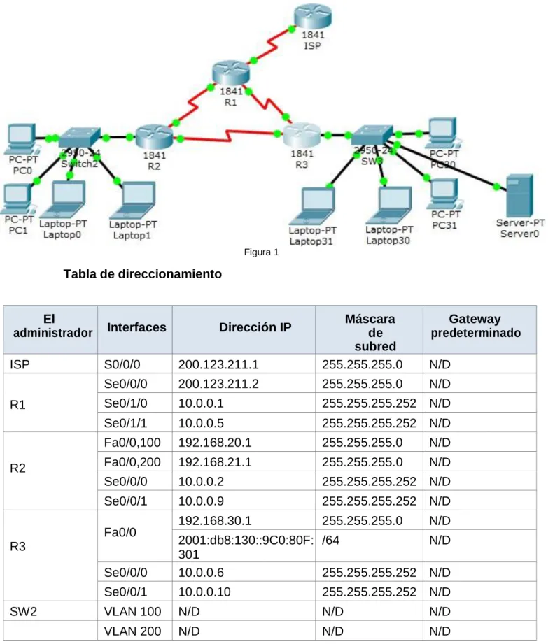
1. INFORME DE HABILIDADES PRACTICAS 1
Figura 1
Tabla de direccionamiento
El
administrador Interfaces Dirección IP
Máscara de subred
Gateway predeterminado
ISP S0/0/0 200.123.211.1 255.255.255.0 N/D
R1
Se0/0/0 200.123.211.2 255.255.255.0 N/D
Se0/1/0 10.0.0.1 255.255.255.252 N/D
Se0/1/1 10.0.0.5 255.255.255.252 N/D
R2
Fa0/0,100 192.168.20.1 255.255.255.0 N/D
Fa0/0,200 192.168.21.1 255.255.255.0 N/D
Se0/0/0 10.0.0.2 255.255.255.252 N/D
Se0/0/1 10.0.0.9 255.255.255.252 N/D
R3
Fa0/0 192.168.30.1 255.255.255.0 N/D
2001:db8:130::9C0:80F: 301
/64 N/D
Se0/0/0 10.0.0.6 255.255.255.252 N/D
Se0/0/1 10.0.0.10 255.255.255.252 N/D
SW2 VLAN 100 N/D N/D N/D
13
SW3 VLAN1 N/D N/D N/D
PC20 NIC DHCP DHCP DHCP
PC21 NIC DHCP DHCP DHCP
PC30 NIC DHCP DHCP DHCP
PC31 NIC DHCP DHCP DHCP
Laptop20 NIC DHCP DHCP DHCP
Laptop21 NIC DHCP DHCP DHCP
Laptop30 NIC DHCP DHCP DHCP
Laptop31 NIC DHCP DHCP DHCP
Tabla 1
Tabla de asignación de VLAN y de puertos
Dispositivo VLAN Nombre Interfaz
SW2 100 LAPTOPS Fa0/2-3
SW2 200 DESTOPS Fa0/4-5
SW3 1 - Todas las interfaces
Tabla 2
Tabla de enlaces troncales
Dispositivo local Interfaz local Dispositivo remoto
SW2 Fa0/2-3 100
14
Situación
En esta actividad, demostrará y reforzará su capacidad para implementar NAT, servidor de DHCP, RIPV2 y el routing entre VLAN, incluida la configuración de direcciones IP, las VLAN, los enlaces troncales y las subinterfaces. Todas las pruebas de alcance deben realizarse a través de ping unicamente.
Descripción de las actividades
1.1 SW1 VLAN y las asignaciones de puertos de VLAN deben cumplir con la tabla 1.
Vlans y Puertos
SW2
Switch>enable Switch#config
Configuring from terminal, memory, or network [terminal]? Enter configuration commands, one per line. End with CNTL/Z. 1(config)#HOSTNAME SW2 SW2(config)#VLAN 100 SW2(config-vlan)#name Laptops SW2(config-vlan)#vlan 200 SW2(config-vlan)#name destops SW2(config-vlan)#exit
SW2(config)#interface range fa0/2-3
SW2(config-if-range)#switchport mode access SW2(config-if-range)#switchport access vlan 100 SW2(config-if-range)#exit
SW2(config)#interface range fa0/4-5
SW2(config-if-range)#switchport mode acces SW2(config-if-range)#switchport access vlan 200 SW2(config-if-range)#interface fa0/1
SW2(config-if)#switchport mode trunk SW2(config-if)#exit
Figura 2 SW3
Switch>enable Switch#config
Configuring from terminal, memory, or network [terminal]? Enter configuration commands, one per line. End with CNTL/Z. Switch(config)#hostname SW3
SW3(config)#Vlan 1 SW3(config-vlan)#exit
SW3(config)#interface range f0/1-24
SW3(config-if-range)#switchport mode access SW3(config-if-range)#switchport access vlan 1 SW3(config-if-range)#exit
15
VLAN Name Status Ports
---- --- --- --- 1 default active Fa0/1, Fa0/2, Fa0/3, Fa0/4
Fa0/5, Fa0/6, Fa0/7, Fa0/8 Fa0/9, Fa0/10, Fa0/11, Fa0/12 Fa0/13, Fa0/14, Fa0/15, Fa0/16 Fa0/17, Fa0/18, Fa0/19, Fa0/20 Fa0/21, Fa0/22, Fa0/23, Fa0/24 1002 fddi-default active
1003 token-ring-default active 1004 fddinet-default active 1005 trnet-default active SW3#
Figura 3
1.2 Los puertos de red que no se utilizan se deben deshabilitar.
SW2
SW2(config)#interface range fa0/6-24 SW2(config-if-range)#shutdown
%LINK-5-CHANGED: Interface FastEthernet0/6, changed state to administratively down
%LINK-5-CHANGED: Interface FastEthernet0/7, changed state to administratively down
%LINK-5-CHANGED: Interface FastEthernet0/8, changed state to administratively down
%LINK-5-CHANGED: Interface FastEthernet0/9, changed state to administratively down
%LINK-5-CHANGED: Interface FastEthernet0/10, changed state to administratively down
%LINK-5-CHANGED: Interface FastEthernet0/11, changed state to administratively down
%LINK-5-CHANGED: Interface FastEthernet0/12, changed state to administratively down
%LINK-5-CHANGED: Interface FastEthernet0/13, changed state to administratively down
16
%LINK-5-CHANGED: Interface FastEthernet0/15, changed state to administratively down
%LINK-5-CHANGED: Interface FastEthernet0/16, changed state to administratively down
%LINK-5-CHANGED: Interface FastEthernet0/17, changed state to administratively down
%LINK-5-CHANGED: Interface FastEthernet0/18, changed state to administratively down
%LINK-5-CHANGED: Interface FastEthernet0/19, changed state to administratively down
%LINK-5-CHANGED: Interface FastEthernet0/20, changed state to administratively down
%LINK-5-CHANGED: Interface FastEthernet0/21, changed state to administratively down
%LINK-5-CHANGED: Interface FastEthernet0/22, changed state to administratively down
%LINK-5-CHANGED: Interface FastEthernet0/23, changed state to administratively down
%LINK-5-CHANGED: Interface FastEthernet0/24, changed state to administratively down
SW2(config-if-range)#exit SW2(config)#
Figura 4
SW3
SW3#config
Configuring from terminal, memory, or network [terminal]? SW3(config)#interface range f0/7-24
SW3(config-if-range)#shutdown
%LINK-5-CHANGED: Interface FastEthernet0/7, changed state to administratively down
%LINK-5-CHANGED: Interface FastEthernet0/8, changed state to administratively down
%LINK-5-CHANGED: Interface FastEthernet0/9, changed state to administratively down
%LINK-5-CHANGED: Interface FastEthernet0/10, changed state to administratively down
17
%LINK-5-CHANGED: Interface FastEthernet0/12, changed state to administratively down
%LINK-5-CHANGED: Interface FastEthernet0/13, changed state to administratively down
%LINK-5-CHANGED: Interface FastEthernet0/14, changed state to administratively down
%LINK-5-CHANGED: Interface FastEthernet0/15, changed state to administratively down
%LINK-5-CHANGED: Interface FastEthernet0/16, changed state to administratively down
%LINK-5-CHANGED: Interface FastEthernet0/17, changed state to administratively down
%LINK-5-CHANGED: Interface FastEthernet0/18, changed state to administratively down
%LINK-5-CHANGED: Interface FastEthernet0/19, changed state to administratively down
%LINK-5-CHANGED: Interface FastEthernet0/20, changed state to administratively down
%LINK-5-CHANGED: Interface FastEthernet0/21, changed state to administratively down
%LINK-5-CHANGED: Interface FastEthernet0/22, changed state to administratively down
%LINK-5-CHANGED: Interface FastEthernet0/23, changed state to administratively down
%LINK-5-CHANGED: Interface FastEthernet0/24, changed state to administratively down
SW3(config-if-range)#
Figura 5
1.3 La información de dirección IP R1, R2 y R3 debe cumplir con la tabla 1.
R2
Router>enable Router #config
Configuring from terminal, memory, or network [terminal]? Enter configuration commands, one per line. End with CNTL/Z. Router(config)#hostname R2
R2(config)#
R2(config)#interface f0/0.100
R2(config-subif)#encapsulation dot1q 100
R2(config-subif)#ip address 192.168.20.1 255.255.255.0 R2(config-subif)#interface f0/0.200
R2(config-subif)#encapsulation dot1q 200
R2(config-subif)#ip address 192.168.21.1 255.255.255.0 R2(config-subif)#exit
18
%LINK-5-CHANGED: Interface FastEthernet0/0, changed state to up
%LINEPROTO-5-UPDOWN: Line protocol on Interface FastEthernet0/0, changed state to up
%LINK-5-CHANGED: Interface FastEthernet0/0.100, changed state to up
%LINEPROTO-5-UPDOWN: Line protocol on Interface FastEthernet0/0.100, changed state to up
%LINK-5-CHANGED: Interface FastEthernet0/0.200, changed state to up
%LINEPROTO-5-UPDOWN: Line protocol on Interface FastEthernet0/0.200, changed state to up
R2(config-if)#exit
R2(config)#interface s0/0/0
R2(config-if)#ip address 10.0.0.2 255.255.255.252 R2(config-if)#no shutdown
%LINK-5-CHANGED: Interface Serial0/0/0, changed state to down
R2(config-if)#exit
R2(config)#interface s0/0/1
R2(config-if)#ip address 10.0.0.9 255.255.255.252 R2(config-if)#no shutdown
%LINK-5-CHANGED: Interface Serial0/0/1, changed state to down R2(config-if)#exit R2(config)# Figura 6 R1 Router>enable Router#config
Configuring from terminal, memory, or network [terminal]? Enter configuration commands, one per line. End with CNTL/Z. Router(config)#hostname R1
R1(config)#interface s0/0/0
R1(config-if)# ip address 200.123.211.2 255.255.255.0 R1(config-if)#no shutdown
%LINK-5-CHANGED: Interface Serial0/0/0, changed state to down
19
R1(config-if)#interface s0/1/0
R1(config-if)#ip address 10.0.0.1 255.255.255.252 R1(config-if)#no shutdown
R1(config-if)#
%LINK-5-CHANGED: Interface Serial0/1/0, changed state to up
R1(config-if)#
%LINEPROTO-5-UPDOWN: Line protocol on Interface Serial0/1/0, changed state to up.
R1(config-if)#interface s0/1/1
R1(config-if)#ip address 10.0.0.5 255.255.255.252 R1(config-if)#no shutdown
%LINK-5-CHANGED: Interface Serial0/1/1, changed state to down R1(config-if)# R1(config-if)# Figura 7 R3 Router>enable Router#config
Configuring from terminal, memory, or network [terminal]? Enter configuration commands, one per line. End with CNTL/Z. Router(config)#hostname R3
R3(config)#ipv6 unicast-routing R3(config)#interface f0/0
R3(config-if)#ip address 192.168.30.1 255.255.255.0 R3(config-if)# ipv6 address 2001:db8:130::9C0:80F:301/64 R3(config-if)#ipv6 dhcp server vlan_1
R3(config-if)#ipv6 nd other-config-flag R3(config-if)#no shutdown
R3(config-if)#
%LINK-5-CHANGED: Interface FastEthernet0/0, changed state to up
%LINEPROTO-5-UPDOWN: Line protocol on Interface FastEthernet0/0, changed state to up
R3(config-if)#interface s0/0/0
R3(config-if)#ip address 10.0.0.6 255.255.255.252 R3(config-if)#no shutdown
R3(config-if)#
%LINK-5-CHANGED: Interface Serial0/0/0, changed state to up
20
%LINEPROTO-5-UPDOWN: Line protocol on Interface Serial0/0/0, changed state to up
% Ambiguous command: "i" R3(config-if)#interface s0/0/1
R3(config-if)#ip address 10.0.0.10 255.255.255.252 R3(config-if)#no shutdown
R3(config-if)#
%LINK-5-CHANGED: Interface Serial0/0/1, changed state to up
R3(config-if)#exit R3(config)#
%LINEPROTO-5-UPDOWN: Line protocol on Interface Serial0/0/1, changed state to up
Figura 8
ISP
Router>enable Router#config
Configuring from terminal, memory, or network [terminal]? Enter configuration commands, one per line. End with CNTL/Z. Router(config)#hostname ISP
ISP(config)#interface s0/0/0
ISP(config-if)#ip address 200.123.211.1 255.255.255.0 ISP(config-if)#no shutdown
ISP(config-if)#
%LINK-5-CHANGED: Interface Serial0/0/0, changed state to up
ISP(config-if)#exit ISP(config)#
21
1.4 Laptop20, Laptop21, PC20, PC21, Laptop30, Laptop31, PC30 y PC31 deben obtener información IPv4 del servidor DHCP.
22
1.5 R1 debe realizar una NAT con sobrecarga sobre una dirección IPv4 pública. Asegúrese de que todos los terminales pueden comunicarse con Internet pública (haga ping a la dirección ISP) y la lista de acceso estándar se llama INSIDE-DEVS.
R1-Config Nat Ipv4 R1>enable
R1#config
Configuring from terminal, memory, or network [terminal]? Enter configuration commands, one per line. End with CNTL/Z. R1(config)#interface s0/1/1
R1(config-if)#ip nat inside R1(config-if)#interface s0/1/1 R1(config-if)#exit
R1(config)#int s0/1/0 R1(config-if)#ip nat inside R1(config-if)#exit
R1(config)#interface s0/0/0 R1(config-if)#ip nat outside R1(config-if)#exit
R1(config)#ip nat pool INSADE-DESV 200.123.211.2 200.213.211.50 netmask 255.0.0.0
R1(config)#access-list 1 permit 192.168.0.0 0.0.255.255 R1(config)#access-list 1 permit 10.0.0.0 0.255.255.255
R1(config)#ip nat inside source list 1 interface s0/0/0 overload
R1(config)#ip nat inside source static tcp 192.168.30.6 80 200.123.211.1 80 R1(config)#router rip R1(config-router)#version 2 R1(config-router)#network 10.0.0.0 R1(config-router)#exit R1(config)#end R1#
%SYS-5-CONFIG_I: Configured from console by console wr
Building configuration... [OK]
R1#show ip nat tr
Pro Inside global Inside local Outside local Outside global tcp 200.123.211.1:80 192.168.30.6:80 --- ---
R1#show ip nat sta
Total translations: 1 (1 static, 0 dynamic, 1 extended) Outside Interfaces: Serial0/0/0
Inside Interfaces: Serial0/1/0 , Serial0/1/1 Hits: 0 Misses: 0
23
Dynamic mappings: R1#
Figura 11
1.6 R2 es un servidor de DHCP para los dispositivos conectados al puerto FastEthernet0/0.
R2
R2>enable R2#config
Configuring from terminal, memory, or network [terminal]? Enter configuration commands, one per line. End with CNTL/Z. R2(config)#ip dhcp excluded-address 10.0.0.2 10.0.0.9
R2(config)#ip dhcp pool INSIDE-DEVS
R2(dhcp-config)#network 192.168.20.1 255.255.255.0 R2(dhcp-config)#network 192.168.21.1 255.255.255.0 R2(dhcp-config)#default-router 192.168.1.1
R2(dhcp-config)#dns-server 0.0.0.0 R2(dhcp-config)#exit
R2(config)#
Figura 12
1.7 R2 debe, además de enrutamiento a otras partes de la red, ruta entre las VLAN 100 y 200.
R2
R2#enable R2#config
Configuring from terminal, memory, or network [terminal]? Enter configuration commands, one per line. End with CNTL/Z. R2(config)#interface vlan 100
R2(config-if)#ip address 192.168.20.1 255.255.255.0 % 192.168.20.0 overlaps with FastEthernet0/0.100 R2(config-if)#exit
R2(config)#interface vlan 200
R2(config-if)#ip address 192.168.21.1 255.255.255.0 % 192.168.21.0 overlaps with FastEthernet0/0.200 R2(config-if)#exit
24
1.8 El Servidor0 es sólo un servidor IPv6 y solo debe ser accesibles para los dispositivos en R3 (ping).
Figura 14
Ping al servidor desde PC30
25
1.10 La NIC instalado en direcciones IPv4 e IPv6 de Laptop30, de Laptop31, de PC30 y obligación de configurados PC31 simultáneas (dual-stack). Las direcciones se deben configurar mediante DHCP y DHCPv6.
Figura 16
1.11 La interfaz FastEthernet 0/0 del R3 también deben tener direcciones IPv4 e IPv6 configuradas (dual- stack).
R3
R3>enable R3#config
Configuring from terminal, memory, or network [terminal]? Enter configuration commands, one per line. End with CNTL/Z. R3(config)#ipv6 u
R3(config)#ipv6 unicast-routing R3(config)#interface f0/0
R3(config-if)#ipv6 enable
R3(config-if)#ip address 192.168.30.1 255.255.255.0 R3(config-if)#ipv6 address 2001:db8:130::9C0:80F:301/64 R3(config-if)#no shutdown
R3(config-if)#exit R3(config)#
26
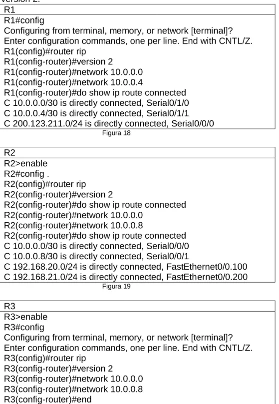
1.12 R1, R2 y R3 intercambian información de routing mediante RIP versión 2.
R1
R1#config
Configuring from terminal, memory, or network [terminal]? Enter configuration commands, one per line. End with CNTL/Z. R1(config)#router rip
R1(config-router)#version 2
R1(config-router)#network 10.0.0.0 R1(config-router)#network 10.0.0.4
R1(config-router)#do show ip route connected C 10.0.0.0/30 is directly connected, Serial0/1/0 C 10.0.0.4/30 is directly connected, Serial0/1/1 C 200.123.211.0/24 is directly connected, Serial0/0/0
Figura 18 R2 R2>enable R2#config . R2(config)#router rip R2(config-router)#version 2
R2(config-router)#do show ip route connected R2(config-router)#network 10.0.0.0
R2(config-router)#network 10.0.0.8
R2(config-router)#do show ip route connected C 10.0.0.0/30 is directly connected, Serial0/0/0 C 10.0.0.8/30 is directly connected, Serial0/0/1
C 192.168.20.0/24 is directly connected, FastEthernet0/0.100 C 192.168.21.0/24 is directly connected, FastEthernet0/0.200
Figura 19
R3
R3>enable R3#config
27
1.13 R1, R2 y R3 deben saber sobre las rutas de cada uno y la ruta predeterminada desde R1.
Figura 21
1.14 Verifique la conectividad. Todos los terminales deben poder hacer ping entre sí y a la dirección IP del ISP. Los terminales bajo el R3
deberían poder hacer IPv6-ping entre ellos y el servidor.
Ping Laptop 31 a R3
28
2. INFORME DE HABILIDAD PRACTICA 2
.
29
1. Configurar el direccionamiento IP acorde con la topología de red para cada uno de los dispositivos que forman parte del escenario.
Figura 24
1.1 Direccionamiento ip
Direccionamiento IP ROUTER MAIMI Router>enable
Router#config
Router(config)#hostname MIAMI MIAMI(config)#int s0/0/1
MIAMI(config-if)#ip address 172.31.21.1 255.255.255.252 MIAMI(config-if)#no shut
%LINK-5-CHANGED: Interface Serial0/0/1, changed state to down MIAMI(config-if)#int g0/0
MIAMI(config-if)#ip address 209.165.200.225 255.255.255.248 MIAMI(config-if)#no shut
MIAMI(config-if)#
%LINK-5-CHANGED: Interface GigabitEthernet0/0, changed state to up %LINEPROTO-5-UPDOWN: Line protocol on Interface GigabitEthernet0/0, changed state to up
MIAMI(config-if)#int s0/0/0
MIAMI(config-if)#ip address 172.31.23.1 % Incomplete command.
MIAMI(config-if)#ip addres 172.31.23.1 255.255.255.252 MIAMI(config-if)#no shut
%LINK-5-CHANGED: Interface Serial0/0/0, changed state to down MIAMI(config-if)#
MIAMI(config-if)#int lo0 MIAMI(config-if)#
30
%LINEPROTO-5-UPDOWN: Line protocol on Interface Loopback0, changed state to up
MIAMI(config-if)#ip add 10.10.10.11 255.255.255.255 MIAMI(config-if)#no shut
MIAMI(config-if)#
Figura 25
Direccionamiento IP ROUTER BOGOTA Router>ENABLE
Router#CONFIG
Configuring from terminal, memory, or network [terminal]? Enter configuration commands, one per line. End with CNTL/Z. Router(config)#HOSTNAME BOGOTA
BOGOTA(config)#int s0/0/0
BOGOTA(config-if)#ip address 172.31.21.2 255.255.255.252 BOGOTA(config-if)#no shut
BOGOTA(config-if)#int g0/0
BOGOTA(config-if)#ip address 192.168.30.1 255.255.255.0 BOGOTA(config-if)#no shut
Figura 26
Direccionamiento Ip R3 Router>ENABLE
Router#CONFIG
Router(config)#HOSTNAME BUENOSAIRES BUENOSAIRES(config)#int s0/0/1
BUENOSAIRES(config-if)#ip address 172.31.23.2 255.255.255.252 BUENOSAIRES(config-if)#no shut
BUENOSAIRES(config-if)#int l04 BUENOSAIRES(config-if)#
%LINK-5-CHANGED: Interface Loopback4, changed state to up
%LINEPROTO-5-UPDOWN: Line protocol on Interface Loopback4, changed state to up
BUENOSAIRES(config-if)#ip address 192.168.4.1 255.255.255.0 BUENOSAIRES(config-if)#int l05
BUENOSAIRES(config-if)#
%LINK-5-CHANGED: Interface Loopback5, changed state to up
%LINEPROTO-5-UPDOWN: Line protocol on Interface Loopback5, changed state to up
BUENOSAIRES(config-if)#ip address 192.168.5.1 255.255.255.0 BUENOSAIRES(config-if)#int l06
BUENOSAIRES(config-if)#
%LINK-5-CHANGED: Interface Loopback6, changed state to up
%LINEPROTO-5-UPDOWN: Line protocol on Interface Loopback6, changed state to up
31
BUENOSAIRES(config-if)#
Figura 27
1.2 Web Server
Figura 28
2. Configurar el protocolo de enrutamiento OSPFv2 bajo los siguientes criterios:
OSPFv2 area 0
Configuration Item or Task Specification
Router ID R1 1.1.1.1
Router ID R2
5.5.5.5 Router ID R3
8.8.8.8 Configurar todas las interfaces LAN como
pasivas
Establecer el ancho de banda para enlaces
seriales en 256 Kb/s
32
Ilustración de las configuraciones hechas en los routers; MIAMI, BUENOS AIRES, BOGTOA en sus interfaces.
2.1 ROUTER MIAMI
Figura 29
2.2 ROUTER BOGOTA
33
2.3 2ROUTER BUENOSAIRES
Figura 31
2.4 CONFIGURACION ROUTERS
ROUTER BOGOTA BOGOTA>enable BOGOTA#config
BOGOTA(config)#router ospf 1
BOGOTA(config-router)#router-id 1.1.1.1
BOGOTA(config-router)#network 172.31.21.0 0.0.0.3 area 0 BOGOTA(config-router)#network 192.168.30.0 0.0.0.255 area 0 BOGOTA(config-router)#network 192.168.40.0 0.0.0.255 area 0 BOGOTA(config-router)#network 192.168.200.0 0.0.0.255 area 0 BOGOTA(config-router)#passive-interface g0/1.30 BOGOTA(config-router)#passive-interface g0/1.40 BOGOTA(config-router)#passive-interface g0/1.200 BOGOTA(config-router)#exit BOGOTA(config)#int s0/0/0 BOGOTA(config-if)#bandwidth 256 BOGOTA(config-if)#ip ospf cost 9500 BOGOTA(config-if)#exit
BOGOTA(config)#exit
BOGOTA#show ip ospf interface serial 0/0/0 Serial0/0/0 is up, line protocol is up
Internet address is 172.31.21.2/30, Area 0
Process ID 1, Router ID 1.1.1.1, Network Type POINT-TO-POINT, Cost: 9500 Transmit Delay is 1 sec, State POINT-TO-POINT, Priority 0
No designated router on this network
No backup designated router on this network
Timer intervals configured, Hello 10, Dead 40, Wait 40, Retransmit 5 Hello due in 00:00:03
Index 1/1, flood queue length 0 Next 0x0(0)/0x0(0)
Last flood scan length is 1, maximum is 1
34
Suppress hello for 0 neighbor(s) BOGOTA#
Figura 32
ROUTER MAIMI MIAMI>enable MIAMI#config
Configuring from terminal, memory, or network [terminal]? Enter configuration commands, one per line. End with CNTL/Z. MIAMI(config)#router ospf 1
MIAMI(config-router)#router-id 5.5.5.5
MIAMI(config-router)#network 172.32.21.0 0.0.0.3 area 0 MIAMI(config-router)#network 172.31.23.0 0.0.0.3 area 0 MIAMI(config-router)#network 10.10.10.0 0.0.0.255 area 0 MIAMI(config-router)#passive-interface g0/1
MIAMI(config-router)#int s0/0/0 MIAMI(config-if)#bandwith 256 MIAMI(config-if)#int s0/0/1 MIAMI(config-if)#bandwith 256 MIAMI(config-if)#ip ospf cost 9500 MIAMI(config-if)#exit
MIAMI(config)#exit MIAMI#
MIAMI#show ip ospf interface serial 0/0/0
Serial0/0/0 is up, line protocol is up
Internet address is 172.31.23.1/30, Area 0
Process ID 1, Router ID 5.5.5.5, Network Type POINT-TO-POINT, Cost: 64 Transmit Delay is 1 sec, State POINT-TO-POINT, Priority 0
No designated router on this network
No backup designated router on this network
Timer intervals configured, Hello 10, Dead 40, Wait 40, Retransmit 5 Hello due in 00:00:03
Index 1/1, flood queue length 0 Next 0x0(0)/0x0(0)
Last flood scan length is 1, maximum is 1
Last flood scan time is 0 msec, maximum is 0 msec Suppress hello for 0 neighbor(s)
MIAMI#
35
ROUTER BUENOSAIRES
BUENOSAIRES>
BUENOSAIRES>ENABLE BUENOSAIRES#CONFIG
Configuring from terminal, memory, or network [terminal]? Enter configuration commands, one per line. End with CNTL/Z. BUENOSAIRES(config)#route ospf 1
BUENOSAIRES(config-router)#router-id 8.8.8.8
BUENOSAIRES(config-router)#network 172.32.23.0 0.0.0.3 area 0 BUENOSAIRES(config-router)#passive-interface l04
BUENOSAIRES(config-router)#passive-interface l05 BUENOSAIRES(config-router)#passive-interface l06 BUENOSAIRES(config-router)#exit
BUENOSAIRES(config)#int s0/0/1
BUENOSAIRES(config-if)#bandwidth 256 BUENOSAIRES(config-if)#exit
BUENOSAIRES(config)# BUENOSAIRES(config)#exit BUENOSAIRES#
%SYS-5-CONFIG_I: Configured from console by console exit
Figura 33
3. Configurar VLANs, Puertos troncales, puertos de acceso,
encapsulamiento, Inter-VLAN Routing y Seguridad en los Switches acorde a la topología de red establecida.
3.1 Configuración de Switches; SWITCHES 1, 3
36
Figura 34
3.2 Configuración de puertos Troncales
37
4 En el Switch 3 deshabilitar DNS lookup.
Figura 36
5 Asignar direcciones IP a los Switches acorde a los lineamientos.
5.1 S1
38
5.2 S3
Figura 38
6 Desactivar todas las interfaces que no sean utilizadas en el esquema de red.
6.1 S1
39
6.2 S3
Figura 40
7 Implement DHCP and NAT for IPv4
7.1 Implementaremos en el router Bogotá, DHCP
40
8 Configurar R1 como servidor DHCP para las VLANs 30 y 40.
Figura 42
9 Reservar las primeras 30 direcciones IP de las VLAN 30 y 40 para configuraciones estáticas.
Configurar DHCP pool para VLAN 30
Name: ADMINISTRACION DNS-Server: 10.10.10.11 Domain-Name: ccna-unad.com Establecer default gateway.
Configurar DHCP pool para VLAN 40
Name: MERCADEO DNS-Server: 10.10.10.11 Domain-Name: ccna-unad.com Establecer default gateway.
Tabla 5
41
El comando domain-name ccna.unad.com, no es reconocido por packet tracer
10 Configurar NAT en R2 para permitir que los host puedan salir a internet
ROUTER MAIMI MIAMI>enable MIAMI#config
Configuring from terminal, memory, or network [terminal]? Enter configuration commands, one per line. End with CNTL/Z.
MIAMI(config)#ip nat inside source static 10.10.10.10 209.165.20.229 MIAMI(config)#int g0/1
MIAMI(config-if)#ip nat inside MIAMI(config-if)#exit
MIAMI(config)#int g0/1
MIAMI(config-if)#ip nat outside MIAMI(config-if)#exit
MIAMI(config)#access-list 1 permit 192.168.30.0 0.0.0.255 MIAMI(config)#access-list 1 permit 192.168.40.0 0.0.0.255 MIAMI(config)#access-list 1 permit 192.168.4.0 0.0.3.255
MIAMI(config)#ip nat pool INTERNET 209.165.200.225 209.165.200.228 netmask 255.255.255.248
MIAMI(config)#ip nat inside source list 1 pool INTERNET MIAMI(config)#do write
Building configuration... [OK]
MIAMI(config)# MIAMI(config)#exit MIAMI#
%SYS-5-CONFIG_I: Configured from console by console
MIAMI#
42
11 Configurar al menos dos listas de acceso de tipo estándar a su criterio en para restringir o permitir tráfico desde R1 o R3 hacia R2.
11.1 NAT1 hacia el router R1 BOGOTA
Figura 45
11.2 NAT 2 hacia el router R2 BUENOS AIRES
43
12 Configurar al menos dos listas de acceso de tipo extendido o nombradas a su criterio en para restringir o permitir tráfico desde R1 o R3 hacia R2.
Figura 47
13 Verificar procesos de comunicación y re direccionamiento de tráfico en los routers mediante el uso de Ping y Traceroute.
Figura 48
44
CONCLUSIONES
Teniendo como base las practicas realizadas en el periodo de estudio del curso CCNA1 y CCNA2 según el análisis del escenario en la actividad practica prueba de habilidades, realizado en modo simulación usando el programa Packet Tracer que permite el diseño y la configuración de los escenarios propuesto para la solución del problema. Con el cual se debe contar de tiempo y dedicación para su completo desarrollo y mejor a un entendimiento, del extensivo curso Cisco se a predio a diseña topologías y direccionarlas, además de la creación de subredes que ayuden a la eficacia de las redes.
45
Bibliografía
Macfarlane, J. (2014). Network Routing Basics : Understanding IP Routing in
Cisco Systems. Recuperado de:
http://bibliotecavirtual.unad.edu.co:2048/login?url=http://search.ebscoh ost.com/login.aspx?direct=true&db=e000xww&AN=158227&lang=es&s ite=ehost-live Lucas,
M. (2009). Cisco Routers for the Desperate : Router and Switch Management, the Easy Way. San Francisco: No Starch Press. Recuperado de: http://bibliotecavirtual.unad.edu.co:2048/login?url=http://search.ebscoh
ost.com/login.aspx?direct=true&db=e000xww&AN=440032&lang=es&s ite=ehost-liv