LIDAR System based on a High Brightness Semiconductor
Laser and Single Photon Counting Detection for Space-borne
Atmospheric CO
2Monitoring
Ignacio ESQUIVIAS (1), Antonio PEREZ-SERRANO (1), Jose Manuel G. TIJERO (1), Mickael FAUGERON (2), Michel KRAKOWSKI (2), Frédéric VAN DIJK (2), Gerd KOCHEM (3), Martin TRAUB (3), Pawel ADAMIEC (4), Juan BARBERO (4), Xiao AI (5), John RARITY (5), Mathieu QUATREVALET (6) and Gerhard EHRET (6)
1. CEMDATIC-E.T.S.I. Telecomunicación, Universidad Politécnica de Madrid (UPM), 28040 Madrid, Spain.
2. III-V Lab Campus Polytechnique, 91767 Palaiseau, France.
3. Fraunhofer Institute for Laser Technology (ILT), 52074 Aachen, Germany. 4. Alter Technology Tüv Nord S.A.U., 28760 Tres Cantos, Spain.
5. University of Bristol, BS8 1UB Bristol, United Kingdom.
6. Institut für Physik der Atmosphäre, DLR, 82234 Weßling, Germany.
Contact name: Ignacio Esquivias ([email protected]).
ABSTRACT:
High brightness semiconductor lasers are potential transmitters for future space LIDAR systems. In this contribution, we propose an all-semiconductor laser source for an Integrated Path Differential Absorption LIDAR system for column-averaged measurements of atmospheric CO2 in future satellite missions. The transmitter design is based on two monolithic Master Oscillator Power Amplifiers, providing the on-line and off-line wavelengths close to the selected absorption line around 1.57 µm. Our design allows the emitters to deliver high power and high quality laser beams with good spectral properties. An output power above 400 mW with a SMSR higher than 45 dB has been demonstrated. On the side of the receiver, our results indicate that the major noise contribution comes from the ambient light. For this reason narrow band optical filters are used in the detection together with high sensitivity and low noise single photon counting techniques.
Key words: Atmospheric sensing, integrated path differential absorption lidar, random modulation continuous wave lidar, master oscillator power amplifier, semiconductor laser
1.- Introduction
The availability of suitable laser sources for accurate measurement of atmospheric CO2 is one of the main challenges in future space missions. We propose an all-semiconductor laser source for an Integrated Path Differen-tial Absorption (IPDA) LIDAR system for column-averaged measurements of atmos-pheric CO2 in future satellite missions [1]. Standard IPDA systems [2] use high peak power optical pulses at two sounding
approach [3] has been selected as the best suited to a semiconductor laser source. Our transmitter design is based on two monolithic Master Oscillator Power Amplifi-ers (MOPAs), providing the on and off-line wavelengths close to the selected absorption line around 1.57 µm. Each MOPA consists of a frequency stabilized Distributed Feedback (DFB) master oscillator, a bent modulator section, and a tapered Semiconductor Optical Amplifier (SOA). This design allows the emitters to deliver high power and high qual-ity laser beams with good spectral properties [4]. On the receiver side, our modeling and simulations indicate that the major noise contribution comes from the ambient light. For this reason narrow band optical filters are used in the detection together with high sen-sitivity and low noise single photon counting techniques.
In this contribution, we present the latest progresses regarding the design, modelling and characterization of the transmitter, the receiver, the Frequency Stabilization Unit (FSU) and the system.
2.- System design
2.1.- The Random-Modulation
Contin-uous-Wave LIDAR approach
Pulsed IPDA LIDAR systems, such as the CO2 and CH4 Atmospheric Remote
Monitor-ing-Flugzeug (CHARM-F) [5] estimate the column concentration of greenhouse gases in the atmosphere by looking at the back-scattered pulse echoes at the end of the opti-cal path, which is either the cloud top or the Earth's surface. The term ‘differential absorp-tion’ refers to the difference of the absorption of a pair of laser lines with slightly different wavelengths: the on-line wavelength (λOn) is
near the center of a CO2 absorption line
while the off-line wavelength (λOff) is set
close to but off the same absorption line. Both wavelengths are close enough such that the two lines exhibit almost identical aerosol attenuation but obviously different CO2
ab-sorption. Hence, the relative absorption by the CO2 molecules can be calculated by the
power ratio of the back-scattered signals at the end of the optical path and it can be con-verted into a column-averaged mixing ratio
thanks to the knowledge of the path length from the round-trip time delay.
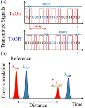
Fig. 1: Illustration of the RM-CW LIDAR technique. (a) Transmitted PRBS signals. (b) Cross-correlation between the emitted PRBS and the received signals allowing distance and differential absorption measurements.
RM-CW LIDAR [6] is capable of obtaining range gated back-scattering information as obtained from pulsed techniques. In RM-CW LIDAR, a Pseudo-Random Binary Sequence (PRBS) is transmitted (See Fig. 1 (a)). The received signal correlated with the original PRBS code gives a range resolved response with a non-ambiguous range determined by the number of PRBS bits (repetition rate) which can be extended further than the trip time corresponding to the atmosphere thick-ness. The auto-correlation property of the PRBS and the temporal shifting of the codes allow the transmission of both wavelengths simultaneously, thus avoiding the beam misalignment problem. Fig. 1 (b) shows an example of the cross-correlation between the received signal and the emitted PRBS. The ratio between the cross-correlation intensities of the reference output and the received sig-nals provides information about the differen-tial absorption optical depth and hence on the dry air mixing ratio of CO2. Furthermore, due
gates with the distance resolution limited by the PRBS bit time (chip time).
2.2.- LIDAR System
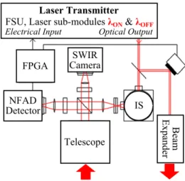
The design of the complete IPDA LIDAR system is shown in the block diagram of Fig. 2. It consists of the laser transmitter, the op-tics for beam transmission and reception and the control electronics. Specifically, the out-put beam from the transmitter is split in two branches: one is sent to the beam expander and then to the atmosphere and the other is used as reference in the comparison with the received signal, for the calculation of CO2
concentration. The reflected light from Earth ground is collected by a reflective telescope with a Field of View (FOV) matching the laser beam divergence and alignment issues are addressed by using a Short Wave Infrared (SWIR) camera.
The main drawback of the proposed RM-CW IPDA system is the degradation of the Signal to Noise Ratio (SNR) in comparison with pulsed systems due to the ambient and detec-tor noise [3]. This effect can be minimized by using a narrow spectral filter at the re-ceiver and by optimizing the detector per-formance. A very high sensitivity detector based on InGaAs Negative Feedback Ava-lanche Diodes (NFAD) is proposed for single photon counting of the received signal [3]. The modulation sequence and the correlation process required by the RM-CW technique are implemented with a Field Programmable Gate Array (FPGA).
Fig. 2: Block scheme of the complete IPDA LIDAR system.
3.- Laser transmitter
The laser transmitter architecture is shown in Fig. 3. It consists of two space compatible laser sub-modules, the control electronics and the Frequency Stabilization Unit (FSU). Two laser chips, one for each sounding fre-quency (λOn, λOff) required for CO2 detection
in IPDA systems, are housed in the laser module, together with the beam forming optics. The back facet output of the laser chips are sent to the FSU through standard Single Mode Fibers (SMF) for frequency stabilization.
Fig. 3: Block scheme of the laser transmitter.
3.1.-Laser Module
The radiation emitted from the back facet of the DFB is expected to be diffraction limited, and therefore can be coupled into a lensed Single Mode Fiber (SMF) aligned to the DFB back facet.
Fig. 4: Photograph of the laser sub-module.
Two mirrors, one for each sub-module, are used for combining the output beams before exiting the laser module (see Fig. 3). Partily reflective mirrors are used in order to al-low power monitoring for each MOPA with two photodiodes placed right after the com-bining mirrors. The laser beams from the two laser chips are placed close to each other at the laser module output, for minimizing footprint errors in the IPDA detection.
3.2.-Frequency Stabilization Unit
For accurate estimation of gas molecule con-centration IPDA LIDAR systems require high frequency stabilization, in order to have precise measurement of the detected power ratio at the selected absorption line [2]. In our case, the proposed absorption line is at 1572 nm. It has been chosen because of its high absorption and low interference from the H2O lines.
Regarding frequency stability and knowledge accuracy, the most critical is the on-line fre-quency, due to the slope in the wing of the line. The linewidth and linewidth knowledge accuracy is expected to be uncritical for our transmitter, because pseudo-random modula-tion dominates the linewidth which is there-fore well known.
In order to achieve these frequency require-ments, we use two opto-electrical feedback
loops for the stabilization of the on- and off-channels coupled to the output of a third opto-electrical feedback loop for CO2
lock-ing.
The light emitted from the back facet of the DFB section of the on-line MOPA and col-lected by the lensed SMF fiber is sent to a fiber coupler. One of the output ports of the coupler is sent to the on-line locking feed-back loop and the other is used for monitor-ing. In the same way, the light emitted from the back facet of the off-line MOPA is sent to a second fiber coupler. One of the outputs is sent to the off-channel locking feedback loop while the other is used for monitoring. We use a master DFB laser that is locked to the selected CO2 absorption line using a
mul-ti pass CO2 reference cell and a custom
feed-back loop based on a commercially available laser frequency locking equipment. The light emitted from the master laser is injected into the on- and off-line frequency locking loops and it is used to stabilize the beat note of the on- and off-line signals with respect to the master laser frequency, with a tunable 350 MHz and with a fixed 10 GHz offsets, re-spectively.
3.3.- Laser Chip
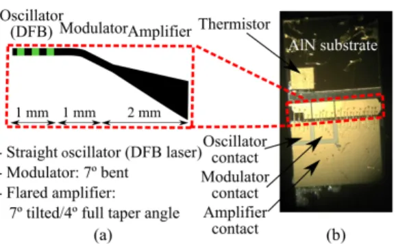
InGaAsP/InP monolithic MOPAs were fabri-cated as the main building block of the laser transmitter. A scheme of the device is shown in Fig. 5 (a). The use of this original structure aims to fulfill the performances required by the IPDA system in terms of high power, frequency stability and good beam quality. The DFB section is accurately frequency stabilized by an external opto-electrical feed-back loop through the FSU. The bent modu-lator section is introduced for implementa-tion of the RM-CW technique in the pro-posed IPDA system. Finally, the geometry of the tapered SOA is optimized in order to provide high brightness output beam with sufficient power and beam quality.
arising from the residual reflectivity at the amplifier output facet [7, 8]. In order to fur-ther decrease the coupling of the residual reflected light at the SOA facet, this facet was slightly tilted respect to the SOA axis. An asymmetrical cladding structure was fab-ricated using a dilute slab composed of InP and InGaAsP (λg = 1.17 µm) in order to
avoid any material development. Indeed this quaternary material is the same as the barrier material. The slab thickness (1.62 µm) has been optimized to decrease the optical con-finement within the p-doped layers as much as possible and to maintain the confinement within the Quantum Wells (QWs) around 2%. This level of confinement is necessary to maintain a low threshold current, a low RIN and a quite large relaxation frequency. The multiple QWs structure was grown by Metal Organic Chemical Vapor Deposition (MOCVD) on n-InP substrates. The active region contains six 8 nm thick compressively (0.85%) strained InGaAsP quantum wells and five 10 nm thick InGaAsP (λg = 1.17
µm) barriers. The photoluminescence peak was 1.57 µm. After a first epitaxy for the fabrication of the DFB section, first order gratings were defined by e-beam lithography and inductively coupled plasma (ICP) reac-tive ion etching. The InGaAsP grating layer was positioned above the active zone and the grating layer thickness was optimized in order to obtain a coupling strength ΚL ~ 1.4. This low value of ΚL should limit spatial hole burning and the associated optical pow-er saturation. Re-growth of p-doped top cladding was then also done by MOCVD. The ridge-waveguides are 3.0 µm wide. This value was found to minimize the thermal saturation while preserving lateral single-mode operation. Bars were cleaved to form 4 and 5 mm long devices. Facets were high reflectivity (HR) coated on the DFB laser backside facet and antireflection (AR) coated on the SOA facet. Chips cleaved from the bars were mounted p-side up on aluminum nitride (AlN) sub-mounts. A thermistor was glued on the sub-mount to better control the chip temperature. Fig. 5 (b) shows a photo-graph of the bent MOPA where the different contacts for the three sections and the
ther-mistor contact for temperature control can be observed.
Fig. 5: (a) Scheme of the bent MOPA. (b) Photograph of the bent MOPA showing the contacts of each section.
The measured CW output power vs. amplifi-er current charactamplifi-eristics for a bent MOPA are shown in Fig. 6 for different modulator section currents and a fixed DFB current of 400 mA. The maximum optical power of around 400 mW corresponds to a modulator current of 300 mA. The static Extinction Ratio (ER) when switching the modulator current between 0 and 300 mA is 26 dB.
Fig. 6: Experimental L-I curves of the bended MOPA for different values of the modulator current. The pump current of the oscillator (DFB) is fixed to 400 mA.
it is not expected at the proposed modulation rate of 25 Mbps.
Fig. 7: (a) Optical spectra for different cur-rent values of the modulator section. The pump current of the oscillator (DFB) is fixed at 400 mA, while the pump current of the am-plifier is fixed at 3 A. (b) Peak wavelength of the optical spectra shown in (a) for the dif-ferent modulator currents.
The output power is limited by the flared SOA thermal saturation. This saturation ap-pears at low current density (2 kA.cm-2) compared with similar structures such as [9] (4.64 kA.cm-2). We think this limitation is due to fabrication issues during the p-side contact annealing. Higher power levels are expected in next fabrication runs.
4.- Conclusion
In this contribution, we report on the pro-gresses in order to achieve space-borne LIDAR measurements of atmospheric carbon dioxide concentration based on an all semi-conductor laser source at 1.57 µm. The com-plete design of the proposed RM-CW IPDA LIDAR has been presented and described in detail. Complete descriptions of the laser module and the FSU have been presented. Two bent MOPAs, emitting at the sounding frequency of the on- and off- IPDA channels,
have been proposed as the transmitter optical sources with the required high brightness. We have demonstrated more than 400 mW output power with a SMSR higher than 45 dB and stable emission. Experimental results on the bended MOPAs have been presented showing a high spectral purity and promising expectations on the high output power re-quirements.
Acknowledgements: This work was supported by the European Commission through the project BRITESPACE under grant agreement no. 313200. I.E., A.P. and J.M.G. also acknowledge support from the Ministerio de Economía y Competitividad of Spain through project RANGER(TEC2012-38864-C03-02). References
[1] http://www.britespace.eu
[2] G. Ehret, et al., “Space-borne remote sensing of CO2, CH4, and N2O by integrated path differential absorption lidar: a sensitivity analysis,” Appl. Phys. B90, p. 593 (2008). [3] X. Ai et al., “Pseudo-random single photon
counting for space-borne atmospheric sensing applications” in IEEE Aerospace Conference, Big Sky, Montana, USA, 2014. [4] M. Faugeron, et al, “High Power
Three-Section Integrated Master Oscillator Power Amplifier at 1.5 µm ”, to appear in IEEE Photon. Technol. Lett., 2015.
[5] M. Quatrevalet, et al., “CHARM-F: The airborne integral path differential absorption lidar for simultaneous measurements of atmospheric CO2 and CH4,” in Proc. 25th
Int. Laser Radar Conf., St. Peterburg, Russia, 2010.
[6] N. Takeuchi, N. Sugimoto, H. Baba, and K. Sakurai, “Random modulation cw lidar,”
Appl. Opt.22, pp. 1382-1386, 1983.
[7] M. Spreemann, et al, “Measurement and simulation of distributed feedback tapered master-oscillator power-amplifiers” IEEE J. Quantum Electron.45, pp. 609–616, 2009. [8] M. Vilera, et al, “Emission characteristics of
a 1.5 µm all semiconductor tapered master oscillator power amplifier”, IEEE Photon. J. 7, pp. 1500709, 2015.
[9] L. Hou, et al, “Narrow linewidth laterally coupled 1.55 µm AlGaInAs/InP distributed feedback lasers integrated with a curved tapered semiconductor optical amplifier,”