Software Product Line for web-based
Geographic Information Systems
Autor: Alejandro Cortiñas Álvarez
Tesis doctoral UDC / 2017
Directores:
Miguel Rodríguez Luaces
Óscar Pedreira Fernández
PhD thesis supervised by
Tesis doctoral dirigida por
Miguel Rodríguez Luaces
Departamento de Computación Facultad de Informática Universidade da Coruña 15071 A Coruña (España) Tel: +34 981 167000 ext. 1254 Fax: +34 981 167160
Óscar Pedreira Fernández
Departamento de Computación Facultad de Informática Universidade da Coruña 15071 A Coruña (España) Tel: +34 981 167000 ext. 6028 Fax: +34 981 167160
Miguel Rodríguez Luaces y Óscar Pedreira Fernández, como directores, acredita-mos que esta tesis cumple los requisitos para optar al título de doctor internacional y autorizamos su depósito y defensa por parte de Alejandro Cortiñas Álvarez cuya firma también se incluye.
A mi familia.
Acknowledgements
First of all, thanks to Miguel, the person who has introduced me to researching and who has invested more time and effort in helping me for many years. Thanks also to Oscar for his help since I arrived at the laboratory and throughout my thesis. I am also grateful for the support and the welcoming of all my colleagues at the Databases Laboratory of the University of A Coruña, especially to Nieves, who has always advised me and has taken care of me, without her help I would not be where I am. My fellow doctoral students, Fernando, Cristina, Adrián, Tirso and even Daniil deserve a special mention, thanks for making this whole path much more pleasant. I also want to thank my colleagues from Enxenio, in special to Carlos, Santi and Alejandro, for their collaboration throughout this work. And to all of you who gather to have lunch every day, sometimes I feel like working just to chat with you.
Besides I would like to thank my friends from Como, Mehdi, Theo, Shruti, Melisa and all the others for having made those three months flown by. Thanks to all those people of CUAC that have been standing me for many years and my colleagues in Spoiler (talking about series. . . seriously). Thanks to Vanisa for those remote talks that help me to disconnect. Thanks to thehillbilliesI have for friends, especially Pata, Seo and Shorkan, who are always there bothering (was it the other way around?). Thanks to Antonio, who finally finished his project.
Lastly, I am very grateful to my family, who are not to blame for anything and who have always trusted and supported me.
Agradecimientos
Ante todo gracias a Miguel, la persona que me ha introducido en la investigación y que más tiempo y esfuerzo ha depositado en mí desde hace ya muchos años. Gracias también a Óscar por su ayuda desde que llegué al laboratorio y a lo largo de mi tesis. Me gustaría agradecer también el apoyo y acogida de todos mis compañeros y compañeras del LBD, especialmente a Nieves, que siempre me ha aconsejado y ha tirado de mí, sin su ayuda no estaría donde estoy. Mención aparte merecen mis colegas doctorandos, Fernando, Cristina, Adrián, Tirso y hasta Daniil, gracias por hacer todo este camino mucho más agradable. También quiero agradecer a mis compañeros de Enxenio, especialmente a Carlos, Santi y Alejandro, por su colaboración a lo largo de este trabajo. Y a todos los que nos reunimos para comer cada día, que a veces apetece trabajar sólo para charlar con vosotros.
Por otro lado me gustaría dar las gracias a mis amigos y amigas de Como, a Mehdi, Theo, Shruti, Melisa y a todos los demás por haber hecho que esos tres meses hayan pasado volando. Gracias a toda esa gente de CUAC que me lleva aguantando ya muchos años y a mis colegas de Spoiler (hablamos de series. . . en serio). Gracias a Vanisa por esas charlas en remoto que me ayudan a desconectar. Gracias a los garrulos que tengo por amigos, sobre todo a Pata, Seo y a Shorkan, que siempre están ahí dando la tabarra (¿o era al revés?). Gracias a Antonio, que por fin se sacó el proyecto.
Por último, muchas gracias a mi familia, que los pobres no tienen culpa de nada y siempre han depositado toda su confianza y su continuo apoyo en mí.
Abstract
Software Product Line Engineering (SPLE) is a research field that seeks to industrialize software development using techniques such as mass-production and mass-customization or reusing software components. A geographic information system (GIS) is an information system that works, in some way, with geographic information. Although each GIS is used in a particular area, there are many features common to all of them. In addition, strong standardization has been carried out so that most GIS software components are interoperable. Consequently, the application of SPLE in this domain is a feasible and interesting problem.
Applying SPLE to a new domain is a complex process and, in order to guarantee the validity of the final design of the SPL and its evolution, it is important to strictly follow a methodology appropriate to the specific domain. Considering that it does not exist a suitable methodology for the context of our work (i.e., web-based GIS applications developed in a software company with several products in the market), we have decided to combine several existing methodologies and extend their scope with additional tasks that will are very useful in our context.
After defining our SPL following this methodology, we found that the traditional techniques to implement SPL are not suitable for our domain, due to the peculiarities and requirements in the development of web-based GIS applications. Therefore, we have defined and implemented a new derivation engine for automatic software generation that maintains the formalities behind SPLE but at the same time provides a new degree of flexibility thanks to the use of a well-known industrial technique: scaffolding.
Resumen
La ingeniería de líneas de producto software (LPS) es un campo de investigación que pretende industrializar el desarrollo de software usando técnicas como la producción y customización en masa, o la reutilización de componentes software. Un sistema de información geográfica (SIG) es un sistema de información que trabaja, de alguna manera, con información de carácter geográfico. A pesar de que cada SIG se utiliza en un área en particular, hay muchas características comunes a todos ellos. Además, se ha llevado a cabo una fuerte estandarización de forma que la mayor parte de componentes software SIG son interoperables. En consecuencia, la aplicación de la ingenería de LPS en este dominio es un problema factible e interesante.
Aplicar ingenería de LPS a un nuevo dominio es un proceso complejo y, para garantizar la validez del diseño final de la LPS y su evolución, es importante seguir de manera estricta una metodología adecuada al dominio concreto. Considerando que no existe una metodología adecuada para el contexto de nuestro trabajo (es decir, aplicaciones SIG basadas en web desarrolladas en una compañía de desarrollo de software con varios productos en el mercado), hemos decidido combinar varias metodologías existentes y extender su alcance con determinadas tareas que servirán para sacar el máximo provecho a nuestro contexto.
Tras la definición de nuestra LPS siguiendo esta metodología, hemos encontrado que las técnicas tradicionales para implementar LPS no son adecuadas para nuestro dominio, debido a las particularidades y requerimientos en el desarrollo de aplicaciones GIS basadas en la web. Por lo tanto hemos definido e implementado un nuevo motor de derivación para la generación automática de software que mantiene las formalidades detrás de las LPS pero, al mismo tiempo, proporciona un nuevo grado de flexibilidad gracias al uso de una conocida técnica industrial: scaffolding.
Resumo
A enxeñería de liñas de produto software (LPS) é un campo de investigación que pretende industrializar o desenvolvemento de software usando técnicas como a producción e customización en masa, ou a reutilización de componentes software. Un sistema de información xeográfica (SIX) é un sistema de información que traballa, de algún modo, con información de carácter xeográfico. Aínda que cada SIX utilízase nun área en particular, existen moitas características comúns a todos eles. Ademáis, levouse a cabo unha forte estandarización de xeito que a maior parte dos componentes software SIX son interoperables. Polo tanto, a aplicación da inxeñería de LPS neste dominio é un problema factible e interesante.
Aplicar enxeñería de LPS a un novo dominio é un proceso complexo e, para garantizar a validez do deseño final da LPS e a súa evolución, é importante seguir de maneira estricta unha metodoloxía adecuada ao dominio concreto. Tendo en conta que non existe ningunha metodoloxía adecuada para o contexto do noso traballo (é dicir, aplicacións SIX baseadas na web desenvoltas nunha compañía de desarrollo de software con varios productos no mercado), decidimos combinar varias metodoloxías existentes e extender o seu alcance con determinadas tarefas que servirán para sacar o máximo aproveitamento ao noso contexto.
Tras a definición da nosa LPS seguindo esta metodoloxía, encontramos que as técnicas tradicionais para implementar LPS non son axeitadas para o noso dominio, debido ás particularidades e requerimentos no desenvolvemento de aplicacións SIX basadas na web. Polo tanto deseñamos e implementamos un novo motor de derivación para a xeración automática de software que mantén as formalidades das LPS pero, ó mesmo tempo, proporciona un novo grado de flexibilidade grazas ó uso dunha coñecida técnica industrial: scaffolding.
Contents
1 Introduction 1
1.1 Background and Motivation . . . 1
1.2 Contributions . . . 6
1.3 Thesis Outline . . . 7
I
Software Product Line Engineering: methodology
9
2 SPLE: state of the art 11 2.1 Basic Concepts . . . 112.2 Advantages of software product lines . . . 14
2.3 Unsolved problems . . . 15
3 Industrial expertise in the definition of a SPL: a new methodology 19 3.1 Introduction and motivation . . . 19
3.2 Definition of a new methodology . . . 22
3.2.1 Requirement Analysis . . . 22
3.2.2 Architecture Design . . . 23
3.2.3 Evaluation . . . 24
3.2.4 Derivation of a product . . . 24
II
Definition of a SPL for web-based GIS
25
4 GIS: state of the art 27 4.1 Introduction . . . 274.2 Basic Concepts . . . 28
4.3 GIS features . . . 29
4.4 GIS software . . . 34
Contents xvii
4.4.2 Spatial DBMS . . . 36
4.4.3 Map Servers . . . 38
4.4.4 Map Visualization Clients . . . 40
4.5 Summary . . . 41
5 Requirements Analysis: identifying our features 43 5.1 Introduction . . . 43
6 Architecture Design: architecture for Web GIS 69 6.1 Introduction . . . 69
6.2 Reference architectures identification and selection . . . 70
6.3 Analysis of architectures of existing products . . . 72
6.4 Elements selection/prioritization . . . 75
6.5 Product Line Architecture Structure Building . . . 78
6.6 Technology analysis: identifying state of the art technologies . . . . 82
6.7 Summary . . . 86
7 Architecture Evaluation and Derivation 87 7.1 Introduction . . . 87
7.2 Architecture Evaluation: maintaining the traceability . . . 88
7.3 Derivation process in our SPL . . . 93
7.4 Summary . . . 95
III
GISBuilder
97
8 SPL implementation techniques & Scaffolding: state of the art 99 8.1 Introduction . . . 998.2 SPLE: Approaches and tools . . . 100
8.2.1 Compositional or positive approach . . . 100
8.2.2 Annotative or negative approach . . . 104
8.2.4 Summary . . . 107
8.3 Scaffolding: industrial generation of code . . . 108
8.3.1 Scaffolding vs SPLE . . . 110
8.3.2 Libraries and frameworks using scaffolding . . . 111
8.4 Summary . . . 112
9 GISBuilder’s design 113 9.1 Introduction . . . 113
9.2 Architecture . . . 114
9.3 Derivation Engine . . . 116
9.4 Runtime Product Preview . . . 121
9.4.1 Motivation and conceptual approach . . . 121
9.4.2 Improving GISBuilder with Runtime Product Preview . . . . 124
10 Validation of GISBuilder 127 10.1 Case of use . . . 127
10.2 Using the specification interface . . . 130
10.2.1 Project: basic data and languages . . . 131
10.2.2 Features: variability selection . . . 133
10.2.3 GUI: designing the interface . . . 133
10.2.4 Menus . . . 134
10.2.5 Data Model . . . 136
10.2.6 Static Pages . . . 137
10.2.7 Forms . . . 138
10.2.8 Lists . . . 139
10.2.9 Map viewers . . . 140
10.2.10 Product Preview . . . 141
IV
Summary of the thesis
143
11 Conclusions and Future Work 145 11.1 Summary . . . 14511.2 Future Work . . . 146
A JSON Schema for our tool 149
B GISBuilder screenshots 167
Contents xix
D Resumen del Trabajo Realizado 203
D.1 Introducción . . . 203
D.2 Estructura de la tesis . . . 208
D.3 Contribuciones y Conclusiones . . . 209
D.4 Trabajo Futuro . . . 210
List of Figures
2.1 Example of a simple feature model . . . 13
2.2 Break-even point for a SPL . . . 15
2.3 Time to market for a SPL . . . 16
3.1 Structure of ProSA-RA2PLA by [NBM13] . . . 21
3.2 Methodology . . . 23
4.1 EIEL user interface . . . 30
4.2 TomTom Go 1600 user interface . . . 31
4.3 Waze application user interface . . . 32
4.4 User interfaces for many different apps: Simplytrack, Flightradar24, Quartix and MarineTraffic . . . 33
4.5 Result of a GIS for the calculation of flooded areas . . . 33
4.6 User interface of a GIS for managing the process of land consolidation 34 5.1 Requirements analysis stage . . . 44
5.2 WebEIEL screenshot . . . 55
5.3 Galician Cultural Heritage screenshot . . . 56
5.4 Via Maps screenshot . . . 57
5.5 Google Maps screenshot . . . 58
5.6 OpenStreetMap screenshot . . . 59
5.7 First level features of the resulting feature model . . . 65
5.8 Data feature and its subfeatures . . . 65
5.9 Gui feature and its subfeatures . . . 66
5.10 Map viewer feature and its subfeatures . . . 67
5.11 User management feature and its subfeatures . . . 68
6.1 Architecture design stage . . . 70
6.2 Web-based GIS architecture according to [Per02] . . . 71
6.3 First generation architecture for GIS . . . 73
6.4 Second generation architecture for GIS: dual architecture . . . 73 6.5 Second generation architecture for GIS: layered architecture . . . . 74 6.6 Third generation architecture for GIS . . . 74 6.7 PLA Structure . . . 79 6.8 Technological architecture of the products . . . 83 7.1 Architecture evaluation and derivation of a specific product stages 88 8.1 Example of a generic in Java . . . 101 9.7 Simplified excerpt of model transformation template . . . 120 9.8 Activity diagram of the development process . . . 122 B.8 Example of menu configuration - editing a View element with
List of Figures xxiii
B.14 Data model: Warehouse entity definition . . . 181 B.15 Data model: a list with the three entities previously defined . . . . 182 B.16 Static pages WYSIWYG editor . . . 183 B.17 List of the static pages to be created for the application . . . 184 B.18 Defining a form to create, edit and remove trucks . . . 185 B.19 Defining a form to create and edit warehouses . . . 186 B.20 Defining a simple form that only shows three properties of the pick
up locations . . . 187 B.21 Defining a list to show only the active trucks . . . 188 B.22 Defining a list to show the pick up locations . . . 189 B.23 Creating a new map for the application . . . 190 B.24 Specifying a map to visualize the trucks managed by the application 191 B.25 Specifying a map to visualize the pick up locations managed by the
List of Tables
5.1 Requirement list . . . 46 5.2 Feature list . . . 53 5.3 Product planning . . . 63 6.1 Services selection . . . 78 7.1 Traceability feature - service . . . 92
1
Introduction
1.1
Background and Motivation
The traditional approach to software development consists of a series of steps that must be repeated for each new product. Requirements analysis, solution design, implementation, testing and maintenance are performed over and over even when similar products are developed. It is still common that software is developed in an artisan way following this process. The problem with this approach is that both software development itself and product maintenance are slow and highly costly processes in order to produce high quality software. For this reason, many efforts have been made to industrialize software development. Software product line engineering and model driven development are two of the main research fields in this direction.
Software product line engineering (SPLE) uses strategies such as mass produc-tion, mass customization or reusable software artefacts to automate the development of software product families. That is, this discipline is used to create similar software systems that are different only in certain characteristics [ABKS13]. A software product line is defined as “set of software-intensive systems sharing a common, managed set of features that satisfy the specific needs of a particular market segment or mission and that are developed from a common set of core assets in a prescribed
way” [CN02]. In short, a software product line allows us to generate a family of similar software products built by assembling and automatically integrating a set of common reusable components. The set of features provided by a SPL is usually organized in what we call afeature model, and each of the products to be generated is defined as the set of features that it provides.
Model driven development (MDD) is a paradigm for applying the modelling advantages to software engineering activities [BCW12]. The two main concepts in MDD are models, which are simplified representations of reality centered on a particular domain, and transformations, which are manipulative operations on these models that allow them to be transformed into new, more refined models, or even source code of the final system. The actual implementation of MDD in the industry is very low [BCW12]. Nevertheless, there is a technique used in industry that is an informal application of some principles of MDD: scaffolding. This technique was popularized in 2005 by Ruby on Rails1, and it allows accelerating the development
of software by generating source code. It is usually used by programmers in the early stages of software development, because scaffolding tools allow to generate repetitive and easily abstracted code from a specification. Other current frameworks using this technique are Grails2, Spring Roo3or Yeoman4.
The objective of SPL and MDD is not only to improve the efficiency in the production of software, but also the quality of the software systems produced. Both seek to change the paradigm of software development from artisanal to industrial production. The difference is that SPL focuses on building product families that share identical and reusable components, which differ only in some features, while MDD generates platform-specific code from a more abstract and flexible model. As a consequence, the range of different products that can be created with MDD is broader than those that can be created by SPL, but products generated by an SPL are easier to specify and are normally ready for production when they are generated [PPP09,CAK+05]. Hence, both approaches seek to automate and industrialize the development of complex software systems, but the tools and features provided by each approach are very different in nature. Previous investigations have resolved that some application domains would benefit from a combination of SPL and MDD [TBD07,CFP08]. Geographic information systems (GIS) are one such domain.
A GIS is an information system with geospatial features and capabilities [WD04]. Within a geographic information system, geographic data such as the shape of a
1http://rubyonrails.org/ 2https://grails.org/ 3
http://projects.spring.io/spring-roo/
1.1. Background and Motivation 3
river or the area of a building can be handled and represented in a map viewer. GIS are widely used in various general-purpose applications (e.g. web search engines, social networks, etc.) and in various fields of research and production (e.g. engineering, resource management, biology, ecology, logistics, etc.). The impulse that has occurred in communication technologies and the improved Internet access allows the current use of GIS in many mobile devices to visualize and manage geographic data stored on computers over the Internet. Furthermore, the advance in the geolocation capabilities allows any common device such as mobile phones can get our position. This has benefited the appearance of new GIS features in existing applications and the improvement of working workflows. Examples of this are all the positioning functionalities of applications such as Facebook5or Twitter6.
Another change in the GIS software provoked by these advances is the increase of the functionalities and use of the geographic information systems based on web. Traditionally, these web-based GISs have provided a small set of features but, with today’s technology, they can be as powerful as desktop GIS applications retaining all the benefits of being a web application.
Geographic information systems have always shared an enormous amount of functionality and features between them, regardless of the GIS application context. Certain requirements, such as storing and indexing georeferenced data, performing location-based queries, displaying information as a set of layers, or grouping layers on different maps are shared by a good number of existing GISs. However, the early components and GIS software used to be implemented following different and incompatible conceptual, logical and physical models. For example, depending on the software used thepolygon data type had a different definition, or the overlaps
predicate had a different semantic meaning in each case. Because of this, it was very complex to develop interoperable applications, software or components because one could not even migrate data from one application to another without implementing an ad-hoc process. To solve this problem, a joint and collaborative effort was undertaken by two organizations, the International Organization for Standardization7 (ISO) by means of the the ISO/TC 211 [fSn] that is defining
the ISO 19100 set of standards, and the Open Geospatial Consortium8 (OGC). Most GIS software now complies with these standards, interoperability between the different components is simple, and equivalent components can be replaced without problem.
Since the functionalities of GIS are very similar between the different
applica-5https://facebook.com/ 6https://twitter.com/ 7
https://www.iso.org/home.html
tions, they usually share a common set of components, such as the map viewer or the geographic data import library. The biggest difference between the different applications is the specific domain to which the GIS is being focused, which directly affects the dataset that is handled by the application. That is to say, it is not the same to make a GIS application that improves the workflow of a transport company, where we can see the position of the trucks, than an application for the identification of agricultural parcels. But even those modules that depend on the data to be handled are very similar to each other and their code can be abstracted and generalized based on specifications such as the data model. Therefore, although each application may have a different purpose, they are all very similar from the point of view of architecture, components and technology.
As a result, we find that web-based GIS applications have many modules that can be produced by assembling components of the more classic SPL style (e.g., a map viewer library with its sub-features, a mapping importer, etc.), but there are other modules that need to be generated specifically for each product depending on some specification (e.g.., all modules related to the data model, such as georeferenced entities, properties, relations, layers, maps, or the structure of the menu, etc.). Current SPL implementation techniques, most of them shown in [ABKS13,MTS+14], are not suitable for generating dynamic code from product
specifications. We find that the scaffolding technique, wich can be considered a subset of the MDD paradigm, can be applied to extend the classical functionalities of SPL and automate the development of those parts of the system. Therefore, our hypothesis is that we can combine SPL and MDD techniques to produce web-based GIS applications more efficiently and with greater quality.
Although the idea of combining SPL and MDD has already appeared in previous research papers [CAK+05,VG07], its practical combination, which is precisely our focus on this work, is far from easy. First, most existing tools for SPL or MDD have emerged from research projects and they are strongly academy-oriented instead of industry-oriented. Therefore, they have some difficulties supporting the wide variety of technologies applied in web applications, geographic information systems and in both types combined. Furthermore, the tools developed to support SPL and the tools developed to support MDD are not the same, and there is no platform capable of combining these two approaches. Therefore, the first objective of this thesis is to design and implement a derivation engine for a SPL that can assemble components from a set of features selected in a feature model, but that it is also able to follow a MDD approach to generate source code by transforming high-level models of the system. Furthermore, the derivation engine must be based on modern software development technologies in order to be used directly in the industry.
1.1. Background and Motivation 5
applications, it is necessary to apply them in a real industry environment. We can achieve this by joining efforts with Enxenio, which is a Spanish SME (small and medium-sized company) with experience in geographic information systems. To take full advantage of this collaboration, the knowledge of experts in GIS architectures, requirements and technology must be considered in the process that defines the SPL. We also have access to existing product code, so it must also be considered when defining the SPL. In addition, geographic information systems are a field with strong standardization and a large collection of service definitions and architectures that must be taken into account. Finally, if the software product line is to be used in the real industry, both the SPL and the products generated will evolve in time. As we have not found a methodology that covers all these points, the second objective of this thesis is to define a methodology to create SPLs that takes into account all these aspects.
Given that the software product line is designed to be used within a SME, we cannot assume that the analysts that will define and generate products are expert domain engineers with background in SPLE. Therefore, the process for the definition and derivation of products must be simple and it must not require deep knowledge on SPL or any specific technology, apart from the ones that are already present in the common industry practice. For this reason, the third objective of this thesis is to develop a tool for the definition and the derivation of the products in a way that its usage is non-intrusive with the current processes within the company. To comply with this, the tool must be developed using web technologies so the tool can be used from any device of the company without requiring the installation of any additional software.
To summarize, the main goal of this thesis is to prove that SPL and MDD techniques can be combined to produce web-based GIS applications more efficiently and with greater quality. In order to do that, we divide this goal into three specific sub-goals:
1. To design and implement a derivation engine that can assemble components using SPL techniques but that it is also able to generate source code using MDD approaches.
2. To define a methodology to create SPLs that is tailored to SMEs in terms of knowledge elicitation and the evolution of the SPL and its products.
1.2
Contributions
Our first contribution is a methodology for the definition of software product lines based on other two methodologies and enhanced by ourselves taking into account the input of experts from industry. Due to the context of our work, we decided to develop a new methodology that can exploit the advantages in our context, such as having a supporting company (Enxenio) with GIS experts and existing products. At the same time, we also looked for existing methodologies that fit our problem, and we have found two different methodologies that combined work in synergy to complement each others: Magro et al. [MGP08] defines a process in six steps but without defining the process of construction of the architecture of the product line; Nakagawa et al. [NBM13] focuses precisely on the definition of the software product line architecture and therefore complements the above. In addition, we have taken into account traceability considerations proposed by Iida et al. [IMY+16], and we
have extended all phases of the methodology to introduce our own steps.
Our second contribution is the design of a software product line for web-based geographic information systems. This design is the result of the application of our methodology. Two derived contributions are:
• An exhaustive list of features for generic web-based geographic information systems, taking into account different existing products.
• An architecture for web-based geographic information systems based on an architecture of reference, specified by standards, and enhanced with features from architectures of existing products.
Our last contribution is a tool for the definition and generation of web-based geographic information systems. This tool follows the specifications determined in the design of our SPL, and it includes several contributions to the state of the art technology for the implementation of software product lines:
• A derivation engine based on scaffolding providing a grade of flexibility not found in the state of the art alternatives.
1.3. Thesis Outline 7
1.3
Thesis Outline
This thesis is composed by three parts. The first part is dedicated to the methodology and it consists of three chapters. Chapter 2 introduces the concepts behind software product lines and it describes the state of the art of the field, including the advantages of SPL and their unsolved problems. Chapter 3 shows the methodology we have defined for the application of software product line engineering in any domain.
The second part covers the application of the previously defined methodology within our context, web-based geographic information systems. In Chapter 4, we make a brief summary of the basic concepts for geographic information systems, and we describe some software related to GIS. In the rest of the chapters of this part, each step of our methodology is addressed: requirement analysis in Chapter 5, extracting requirements and features from existing products; architecture design in Chapter 6, where we study the reference architectures for GIS and we select one as our own; evaluation and derivation of the products in Chapter 7, showing the traceability between the features and the architecture and the details regarding the derivation of specific products.
Part I
Software Product Line
Engineering: methodology
2
Software Product Line Engineering:
state of the art
2.1
Basic Concepts
Traditionally, the development of every software product goes through a series of steps: elicitation of requirements, design, implementation, testing and maintenance. When a software development company has to build a family of products, all the stages mentioned must be done for each one of them, even when the products share functionalities or are focused in the same specific market. The downside of this approach is that it requires high development and maintenance costs in order to produce high quality products, while the time to market for each product is long since development starts from scratch.
In other classic manufacturing industries, such as the automotive or the textile, the way the products are built went from a manual manufacturing process to industrial processes that use proper machinery [KS90]. This change allowed industries not only to produce their products massively, but also to confront the rising demand for individualised products [PBL05], i.e., mass-customization, and large-scale production of goods tailored to the individual customers’ needs [Sta87].
Software product lines engineering(SPLE) [Bos00,PBL05,vdLSR+07,ABKS13]
is a discipline that aims at applying the same kind of evolution to the way software is built, i.e., applying mass-production, mass-customization and reuse strategies to software development. In [CN02], Clements provides the most well-known definition of a software product line (SPL):
Asoftware product lineis a set of software-intensive systems sharing a common, managed set of features that satisfy the specific needs of a particular market segment or mission and that are developed from a common set of core assets in a prescribed way.
This is, a software product line is a family of software products sharing features developed from a common set of reusable core assets that can be combined and configured in different ways for different products. A SPL separates the development of these core, reusable assets (i.e., the platform), and the development of the actual applications (i.e., the products). This definition includes five fundamental concepts: • “a set of software-intensive systems. . . ”: a SPL does not pretend the development of a single product, but of many similar products (i.e., a family of products). Therefore, a domain engineer has to decide the scope of the products to build within a SPL.
• “. . . common, managed set of features. . . ”: each product built within a SPL shares a set of features with every other product of the family.
• “. . . satisfy the specific needs of a particular market segment or mission. . . ”: a SPL makes only sense to produce specialized products, this is, a set of products solving similar problems.
• “. . . a common set of core assets. . . ”: the products within a SPL are built using the same components. This is, the code of the different generated applications is shared and not unique for each application. In order to generate products that support variable requirements, a domain engineer has to specify variability within the set of components of the SPL. Therefore, some of these core assets are optional or variants.
2.1. Basic Concepts 13
Figure 2.1: Example of a simple feature model
used in product line engineering to specify and communicate commonalities and differences of the products between stakeholders, and to guide structure, reuse, and variation across all phases of the software life cycle [ABKS13]. The platform of a SPL is modelled as a set of features, and variability management involves the tasks of identifying and defining the platform features, defining the functional and technological architectures of the product, and defining the product line configuration and derivation processes. Hence, variability management is one of the main tasks in SPL development. There are many modelling techniques to identify and define the platform features, such as FODA (Feature Oriented Domain analysis) [KCH+90], FORM (Feature Oriented Reuse Method) [KKL+98],
FM (Feature Modeling) [CGR+12], DM (Decision Model) [SRG11], or OVM (Orthogonal Variability Model) [PBL05].
Features are usually classified within a feature model, which represents the features of a family of products, the relationship among them and whether if a feature is common (mandatory), alternative or optional [KCH+90,CHE05]. A
simple feature model can be seen in Figure 2.1.
A product is specified by a feature selection, i.e., a subset of the features of the product line. However, not every subset of features is valid since there are relationships among the features andcross-tree constraints[Bat05] that need to be fulfilled. In Figure 2.1 we can see that the feature “standardDataImport” has two
sub-features, “csvImport” and “spreadsheetImport” in an OR relationship. This means that if a product includes the feature “standardDataImport”, then it must also include at least one of its sub-features in order to be a valid product of the SPL. In Figure 2.1 we can also see the cross-tree constraint “standardDataImportimplies
a feature model complies with the restrictions and relationships specified on it and therefore a product can be generated from this selection of features. Besides this operation, there are many more useful ones associated to feature models [BSRC10], such as number of productsorvalid feature model.
2.2
Advantages of software product lines
The main target of SPLE is to be able to build customized products at a fraction of the cost, solving customers needs with full products specifically crafted from their requirements.
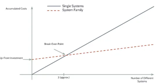
The evolution of costs between conventional development and SPL is very different. Following a traditional approach, this cost grows linearly as the number of products to be developed increases. On the contrary, the cost of developing a SPL is very high initially, but it is being amortized with each new product of the family that is built. According to [PBL05], thebreak-even point for the cost of developing a SPL is when the number of products of the family developed is three. From that number, the SPL offers very remarkable development cost savings especially if we also consider the maintenance of the products, as we can see in Figure 2.2.
In a conventional environment, a very common approach is “copy & own”. A developer starts by copying a previous application similar to the one he or she needs to built, and from there the copy evolves independently. This is applied not only for full applications but also for every core asset. The similarity between the two applications serves to speed development, but in no case for their maintenance. In case a bug is discovered, the development team in charge of the maintenance must debug the code in both applications. In case new features are required, they will have to develop them in both applications. This is, the similarity between the applications is not exploited to reduce the maintenance costs. Reuse is opportunistic, and the management of similarity (common parts and variable parts) is secondary. Therefore, the traditional environment tends to focus on the product: each conventional product is maintained and human teams also tend to fragment in this way. The company does not take advantage of the potential synergies that could be derived from the similarity between products, and the number of different products that can be managed effectively is very limited.
2.3. Unsolved problems 15
Figure 2.2: Break-even point for a SPL
are capitalized by all products. An error detected in a product can be relatively easy to correct in all products of the line thanks precisely to the existence of the common framework offered by the product line. As a straight consequence from this point, thequality of the products is enhanced. The products built within a SPL are much less prone to have bugs because their code has already been tested for the rest of the products already built.
The last main advantage of using a SPL is the reduction of time to mar-ket [PBL05], often a very critical success factor. Although the time to market for the first products of a SPL is higher, because the common artefacts have to be built first, as soon as the SPL is developed and running the time to market of new products is shortened since most of the code of the new products is already written. As opposite, in traditional development, this time is always linear to the number of products (see Figure 2.3). Even in the case that a customer requires a feature not provided by a SPL, a similar product an be generated with all the rest of the features and then this new feature can be added, shortening anyway the time to market of this new application.
2.3
Unsolved problems
Figure 2.3: Time to market for a SPL
proposed, SPL still pose many challenges from the research point of view [MP14]. Some of them as discussed below.
• Optimizing the scope of a SPL. Instead of developing very specialized product families, it would be interesting to optimize the scope of a product taking into account not only market aspects but technical aspects such as the life-cycle management of features, the core assets which implement them and the product architecture. Finally, the economic viability of the whole product line has to be considered as well.
• Describing the interrelation between scope, requirements, features and other development activities. This is, traceability has to be explicitly stated between all the stages of the development of a product within a SPL. This way, the impact of requirement changes and the evolution of both the platform of the SPL and the product can be properly handled. Maintaining a clear traceability also facilitates changing a specific core asset for a new version, for example.
2.3. Unsolved problems 17
have to be managed by th SPL in all the stages of the development process, from the design of the products to their maintenance, going through the derivation of the application-specific code. We deal with one of such domains in this work, web-based geographic information systems (see Chapter 5). In this work we address each one of this issues. The methodology we use to approach the definition of our product line, described in Chapter 3, specifically provides tasks for solving the first and second issue: most of the decisions regarding the product line are solved by taking into account technical aspects of existing products, literature and technical knowledge from experts; at the same time, traceability is maintained all over our process. Furthermore, handling application-specific deviations is totally achieved in our product line from the moment we deal with specific data model specifications for each product.
To conclude, the application of software product lines in the development companies of software has been limited to very specific contexts such as the development ofembedded systems[BRN+13,WCK06,Van02]. In other more complex
3
Industrial expertise in the definition of a
Software Product Line: a new methodology
3.1
Introduction and motivation
One of the objectives of this work is to use the resulting tool within a real software development company, Enxenio. In order to achieve this goal, we have had the collaboration of GIS experts from the company all over our process, taking us to a privileged and unusual context for carrying out this work. Enxenio is a Spanish small and medium enterprise with expertise in geographic information systems. In fact, this company is a leading provider of web-based geographic information systems at the Galicia region, with many previous projects for the public administration and private clients. Enxenio has collaborated with the Database Laboratory at the University of A Coruña for a long time, and several works, such as [LPFCP09,BCLF+07,PBF+07], are some results from this relationship. For our
present work, Enxenio has been helping with their expertise and their existing web-based GIS applications. This collaboration is not altruistic since Enxenio would benefit greatly from the outcome of this thesis, since the application of SPLE for the development of future GIS would give the company a strategic advantage.
In order to make the best from this collaboration, we have looked for the
most adequate methodology for the definition of our SPL. We have found that the methodology to follow must comply with the next requirements:
• The methodology has to make the role of experts with knowledge about architectures, requirements and technology explicit.
• Considering that direct access to the souce code of the products may be provided, the methodology must take the source code into account.
• The software product line domain (in our case, geographic information systems) may have undergone a strong standardization effort that the methodology must not ignore.
• Finally, if the software product line is to be used in the real industry, the platform and the generated products will evolve and therefore, the methodology must facilitate handling this evolution.
We have found two different methodologies that comply with some of this requirements: Magro et al. [MGP09] and Nakagawa et al. [NBM13].
Magro et al. [MGP09] defines six steps based on the works of Bosch [Bos00], DSouza & Wills [DW99], and Mili et al. [MMYA02], and shows an example of its application for the construction of a SPL for validation systems. The six steps defined in this work are:
1. Definition and analysis of the domain, not only to use this information in furthers steps of the process but also to check if the application of SPLE in the selected domain is feasible and advantageous.
2. Product planning. All kind of requirements associated to the different products of the domain have to be accounted for.
3. Design of the architecture of reference by identifying the architectural components, their design and their interactions.
4. Development of the reference architecture components. This fourth step consisted in specifying and analysing the components of the architecture. 5. Architecture evaluation in order to detect problems and drawbacks. 6. Derivation of a specific product.
3.1. Introduction and motivation 21
1. Reference architecture identification/selection, in which the reference archi-tecture is selected taking into account the needs and the scope of the product line.
2. Elements selection/prioritization. They sort the elements from the reference architecture in order of importance, and even not all of them need to be considered for the product line.
3. PLA structure building, the step in which the product line architecture is designed.
4. Variability model building. The PLA variability is identify and designed in this step.
5. PLA evaluation to check if the elements from the reference architecture that were considered important for the product line were indeed added to the final PLA.
Figure 3.1: Structure of ProSA-RA2PLA by [NBM13]
addition, we also considered the work of Diaz et al. [DPG14], since the traceability among the requirements and the PLA is a key issue for guaranteeing the SPL maintenance [AK04]. This issue was also considered by Iida et al. [IMY+16] for the
construction of an automotive braking system SPL.
3.2
Definition of a new methodology
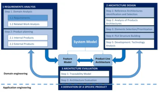
We have defined a new methodology based on the two previous ones, mentioned above, that we consider complementary one to each other, and some extensions related to other issues that we consider critical to take advantage of our situation. We can see our methodology in Figure 3.2. The methodology is framed into the two levels of SPLE: domain engineering and application engineering [PBL05]. The application engineering stage is in charge of the derivation of products, whereas the domain engineering stage is divided into three phases (see Figure 3.2). Among these two levels we define a process which consists on four activities or stages of high level that are executed iteratively. The first stage is therequirements analysis, resulting on the definition of the feature model of the SPL. The second stage is the
architecture design that leads to the design of the product line architecture. Next, the third stage is the architecture evaluation, whose result is the identification of issues in the feature model or in the product line architecture. This may lead to a new iteration of the process, going again to the first stage. The last stage is the
derivation of a specific product in the the application engineering level. Each one of this stages is divided into steps or tasks which are described next. The steps that are based on another methodology are coloured in blue in the figure. The steps proposed by us are coloured in white.
3.2.1
Requirement Analysis
The first stage of our process is the requirements analysis, composed in turn by in two steps: domain analysis and product planning.
3.2. Definition of a new methodology 23
Figure 3.2: Methodology
requirements that have not appeared previously in product of the company but still are interesting. This is a good point specially to help designing an SPL even more prepared for its evolution. In addition, analysing the related work may reveal other SPLs of the domain that could help and not starting from scratch.
The product planning step considers all kind of requirements associated to the different products that can result from the SPL deployment (see the step 1.2, Figure 3.2). But it considers not only those that belong to the company (see the step 1.2.1, Figure 3.2), but also it is important to consider other projects that are known or relevant in the domain (see the step 1.2.2, Figure 3.2). Once the phase is complete, from these complete analyses of requirements, a feature model should be constructed.
3.2.2
Architecture Design
Section 6.2). Next step, analysis of products architectures, is added in top of the existing methodology to contemplate the architectures used by previously developed products in the company (see the step 2.2, Figure 3.2). Analysing and taking into account these architectures is interesting since it may enrich the architecture of the SPL. The steps 3 and 4 are proposed by Nakagawa et al. In the elements selection/prioritization the elements of the architecture are identified and selected (see the step 2.3, Figure 3.2), whereas in thePLA structure buildingthe architecture is designed (see the step 2.4, Figure 3.2). Finally, we added a new step,development: technology analysis, to analyse the technology requirements in order to determine needs and interoperability problems, once again benefiting from our relationship with Enxenio (see the step 2.5, Figure 3.2). This step is also important since it helps to plan the technology evolution. As a result of this second phase, a PLA is obtained.
3.2.3
Evaluation
The third stage consists in mapping the features and architectural elements, in order to guarantee that all features of the SPL are supported by the PLA (see the stage 3, Figure 3.2). This is important not only to observe and guarantee the coherence between the feature set and the PLA, but also to prepare the SPL for its evolution. In these steps, it is important to check that there are no inconsistencies or drawbacks between previous stages and the results obtained. If something is missing, this should be solved in previous stages and the process starts again from stages 1 and 2, checking again all the steps (see the feedback arrows, Figure 3.2).
3.2.4
Derivation of a product
Part II
Definition of a Software
Product Line for web-based
Geographic Information
Systems
4
Geographic Information Systems:
state of the art
4.1
Introduction
In Part I we have described a new methodology that benefits of the particular context of this work whereas it is still based on proven methodologies from the literature. Choosing a methodology is the obvious first step in order to define our software product line with the formalism that is required if we want to guarantee the quality of the design and the right and managed evolution of the product line. Now that the methodology to apply is explained, in Part II we can proceed with the design of a software product line for web-based geographic information systems. Some steps of the methodology require to study the domain for the SPL, web-based geographic information systems, from a more technical point of view. For example, we need to define the list of requirements of this domain and also we need to study the existing reference architectures. Therefore, before starting this process, in this chapter we describe GIS from a more functional point of view, giving the reader an idea of what a GIS is and providing some examples of GIS applications and features. We also enumerate a list of software used by GIS to provide part of the features.
4.2
Basic Concepts
Geographic information, displayed as paper maps, has been one of the driving forces behind the progress of our society for many centuries. Until a few decades ago the representation, manipulation and synthesis of geographic information was limited to the use of paper maps, and these tasks were limited to manual, non-interactive processes. The exponential improvement in the performance of IT-based technologies and the increasing demand for manipulation and interactive analysis of geographic information have triggered the need for geographic information systems (GIS).
GIS are used in many fields, each one of them with its specific point of view. Due to that, there are many definitions of what is a GIS:
• A geographic information system is an application to assist in making decisions related to geography [HA03,LGM15].
• A geographic information system is a set of computer tools that allow analyzing and performing geographic type simulations [LT92,BMML15,
RSV01].
• A geographic information system is a set of data structures and algorithms to represent, query, manipulate and visualize geographic information [WD04,
RSV01].
We can make a more complete definition based on all the mentioned: a geographic information system is a set of software tools to model, represent, store, manipulate, query, analyze and display information that includes a geographic component. We consider a geographic information system as a set of computer tools without having into account the organizational and business aspects of its use, which are mentioned, for example, in [HA03]. In addition, the system must be able to model, represent and store geographic information by providing tools for conceptual modeling of applications, representation of information in data structures, and efficient storage [MPV05,SC03]. Finally, the system must allow the analysis of information by providing tools for the manipulation of the stored information, its querying and its visualization [YG05].
GIS is a field that has been receiving a lot of attention lately. We can note its presence in applications used everyday by millions of people, like Google Maps1, or social networks with location-based features like Facebook or Twitter. Google Maps and Google Earth2 represent an inflection point regarding web-based GIS.
1
https://maps.google.com
4.3. GIS features 29
Before these two applications appeared, web map viewers were primitive and very focused on specific fields. Since they appeared, they have laid the foundations of how a web-based GIS should be. Besides these well-known examples, there are many disciplines using GIS to improve and facilitate its work, such as cartography, biology, ecology, transportation and warehouse logistics. GIS has also reached the mobile systems thanks to the huge evolution in communication technologies and the increased penetration of Internet access.
Even though GIS are used in many disciplines and with a variety of purposes, there are many features shared between almost every one of them. Examples of these common features are storing and indexing geo-referenced data, displaying information as a set of layers, or displaying information in map viewers with zooming and panning capabilities. At first, even with similar features, the software artefacts used to implement each GIS followed different and incompatible conceptual, logical and physical data models. For example, even a simple concept like the data type polygon had inconsistent definitions between GIS technologies. In the last years, the Open Geospatial Consortium (OGC) and the International Organization for Standardization (ISO) have defined a set of standards. With these standards being followed by most software artefacts, these artefacts become interoperable and because of this, a current GIS application can switch its components easily. The standardization processes also affected the architectures and services provided by the geographic information systems, establishing a series of standard services that include the most common ones. We detail this part of the standards in Section 6.2 as part of our methodology.
4.3
Geographic Information Systems features
Current geographic information systems provide lots of features. The most important is the visualization of maps, with the mentioned Google Maps and Google Earth as the two most representative examples. Furthermore, there are GIS features integrated in general purpose applications that do not require any map viewing. Anyone with a mobile device could be using this features without even noticing. For example, when a person publishes a tweet in Twitter, he or she has the option to add the geographical location of the device to the tweet so all his followers can know where was the message originated.
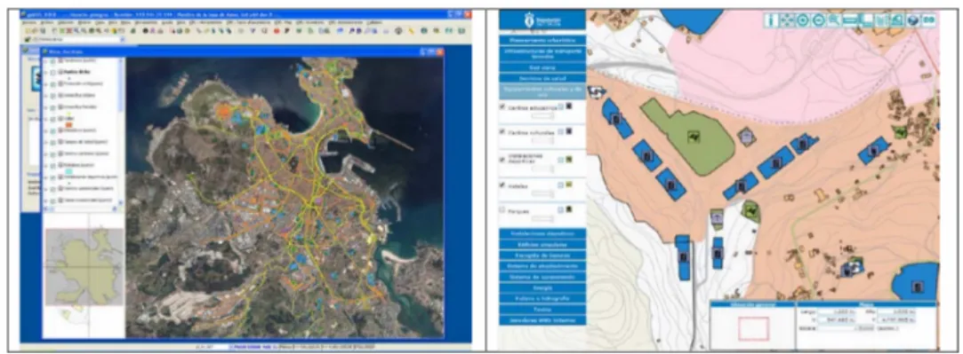
Figure 4.1: EIEL user interface
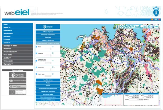
developed by the Databases Laboratory of the University of A Coruña since 2000 [BCLF+07]. This geographic information system consists of a cartographic
inventory of the infrastructures and the equipment of the province that allows to manage of the territory, to verify the correct provision of services and to coordinate the services of different municipalities in common actions. This geographic information system has two different tools: a web-based map viewer that allows the user to visualize the information entered from the management tool (WebEIEL3), and a desktop tool available for the technical staff of the Provincial Council and of the municipalities of the province (gisEIEL4).
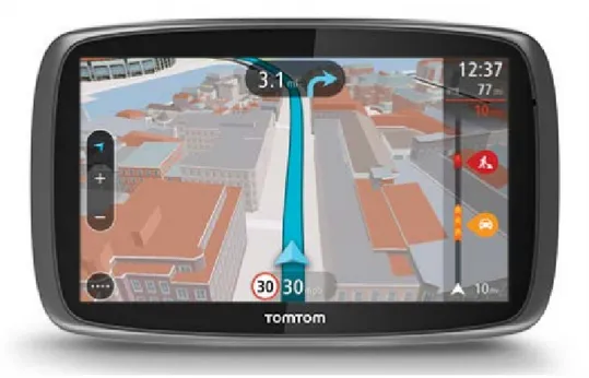
Another area in which geographic information systems are currently being used daily by lots of people are navigation devices. Such devices have emerged thanks to the development of the global positioning system (GPS), initially only for military use, in the 1960s, but extended to its civil use since the 1990s. This system allows the localization of an object through a series of satellites. A GPS receiver is incorporated into a mobile device which is capable of accurately determining its location. In addition, the road network is represented by a graph in which the nodes correspond to intersections of the roads and are labelled with the permitted turns, and the edges correspond to segments of the roads and are labelled with the allowed direction, the length, and the type. With this information the system can compute the optimum route between two points taking into account factors such as distance or time required. In addition, the system can show the user a map of the area with the location, direction and speed of the vehicle. This type of devices include also functionalities for calculation and communication of routes, which can
3
http://webeiel.dicoruna.es/
4.3. GIS features 31
Figure 4.2: TomTom Go 16005 user interface
include in these calculations variables in real time such as current traffic, road events such as accidents or atmospheric difficulties.
Initially, GPS devices were designed and marketed independently only to provide this feature, and they are the only devices that can manage to do that. Some brands were very popular, such as TomTom6(see Figure 4.2). However, with the emergence
of the smartphones which include GPS receivers themselves, nowadays most of these features can be used by them (see Figure 4.3), with different and numerous applications providing this kind of features and even more than the previous GPS devices.
The current high availability of devices with GPS receivers and mobile com-munication networks allows the use of geographic application systems to build fleet control tools. In this case, besides using a vehicle navigation device, this device communicates to a central server its location using mobile technology (GSM, GPRS, UMTS, or HSDPA). The server is responsible for storing the location of the vehicles and it can use this information to perform the tasks that are needed, for example, locating stolen vehicles, picking and delivery planning in parcel companies,
5https://www.tomtom.com/es_es/drive/car/products/go-6100-europe 6
https://www.tomtom.com/es_es/
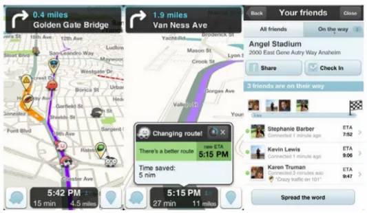
Figure 4.3: Waze7 application user interface
calculating the nearest vehicles for a taxi stand or managing traffic. Currently, there are different commercial systems following this philosophy, both for vehicles, ships and aircraft (Figure 4.4).
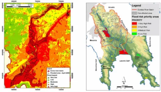
A more specific scope for geographic information systems more focused on simulation instead of management is the analysis of flooded areas. In this case, a digital terrain model is used to represent the height of each point (usually visualized on a 2D map using color), with a model of the hydrographic network representing the river channel and the river flow rate that can withstand naturally. From this information, together with data about precipitations or thawing in the area, the risk of flooding at each point of the terrain can be calculated [EIA+11] (Figure 4.5).
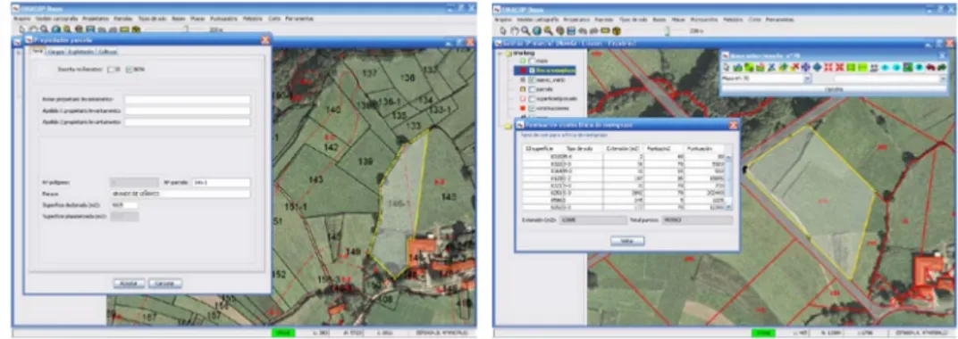
All the engineering disciplines that work with the terrain are frequent users of geographic information systems (road engineering, forest engineering, agronomic engineering). One example is the process of land consolidation (Figure 4.6), in which a new distribution of the properties in an area is carried out to increase the average size of the plots, reducing the smallholding and facilitating its exploitation. To do this, the geographic information system should include information about the
11https://www.simplytrak.com/ 11https://www.flightradar24.com/ 11
https://www.quartix.net/
4.3. GIS features 33
Figure 4.4: User interfaces for many different fleet management apps: Simplytrack8, Flightradar249, Quartix10and MarineTraffic11
Figure 4.6: User interface of a GIS for managing the process of land consolidation
types of soil in the area, existing plots and their current owners, and should allow the definition of new replacement farms by automatically performing calculations and quality controls, allowing the technicians to work quickly and efficiently.
4.4
Geographic Information Systems software
To provide the reader with an idea of GIS tools, in this section we describe different types of resources and real tools that allow developers and users to implement and access GIS features.
There are currently many accessible projects whose purpose is the collection of information in the field of GIS or space DBMS. In this sense, these projects do not provide specific tools or resources, but act as repositories to find other existing projects.
The Open Geospatial Consortium12 is dedicated to the definition of standards
for geographic information. However, it is possible to find in this portal different proposals, articles and discussions on the different standards and technologies used. The organization also provides access to validation tools to check compliance with its standards, as well as a repository of tools conforming to those standards13.
The Open Source Geospatial Foundation14works mainly as a project incubator
of open source software projects related to spatial information.
12http://opengeospatial.org 13
http://www.opengeospatial.org/resource/products/compliant
4.4. GIS software 35
4.4.1
Commercial GIS tools
In this section some commercial tools supporting GIS features are briefly introduced. ArcGIS, by ESRI15, is currently the market leader and has a very wide range
of integrated functionalities as well as the possibility to integrate with a multitude of external tools.
ArcGIS has connectors for databases with SFS (Simple Feature Specifica-tion [fSi]) support such as Oracle Spatial or PostGIS. In addition, it also provides support for many other DBMS, such as Access, Oracle, DB2, SQL Server or Informix. Two data servers are provided, ArcSDE and ArcIMS, which allow the integration of geographic information from different environments by sending it to ArcGIS desktop systems or to other specific applications.
The platform has many functionalities for managing geographic information, both in the vector model and in the raster model. It also provides a free viewer, called ArcExplorer16.
ArcGIS stores and exports information in Shapefile (SHP) format. This format is so widely used that nowadays it can be considered the de facto standard in geographic information systems. The technical description of this format has been published by ESRI [ESR], and it is used as an exchange format of geographic information thanks to many libraries that implement its functionalities. Shapefile allows the general inclusion of alphanumeric and geographic data. However, and despite being widely used, it has some limitations, such as not allowing geometries of different types in the same file.
Hexagon GeoMedia17 can be considered the great rival of ESRI today. It
MapInfo20 provides support for the most common databases and spatial
information formats, conforming to standards such as WMS [fSj] and WFS [fSl], and advanced functionalities for vector and raster information analysis, publication of thematic maps, etc.
AutoCAD Map 3D21, which is part of the family of tools AutoCAD by
Autodesk, provides more specific functionality that allows access to both spatial information and CAD information within the tool. Autodesk Infrastructure Map Server22 is also a map server that allows the publishing GIS and CAD information.
Bentley Map23 is the evolution of the Microstation Geographics tool. It allows the management of vector and raster information, it supports numerous GIS information formats and specific functionalities such as visualization and 3D processing.
All these tools have the usual advantages and problems in commercial products. On one side, the products are available immediately, have a large set of features and the support provided by a large company. In addition to the main applications, the product packages for these tools usually include different utilities to extend the functionalities and facilitate the integration with other systems of the same family. However, the features provided by these products, integrated into large specific packages, may not fit the specific needs of many companies since the product is normally sold in closed packages. On the other hand, since these products are not open source, the software has to be used as a black box, which prevents any access, inspection or modification beyond the extension points defined by the tool itself.
4.4.2
Spatial DBMS
This section describes the main database management systems with support for spatial information.
Oracle Spatial24, currently known as Oracle Spatial and Graph, is a plugin
that adds spatial functionalities to Oracle 11g DBMS.
In the last versions, Oracle has included in their DBMS the component Oracle Locator, providing the most basic tools to allow working with spatial information. Available functionalities include specific data types and operators, following OGC
![Figure 3.1: Structure of ProSA-RA2PLA by [NBM13]](https://thumb-us.123doks.com/thumbv2/123dok_es/3988524.675015/47.892.240.657.597.941/figure-structure-of-prosa-ra-pla-by-nbm.webp)