Active
vibration
control
design
using
the
Coral
Reefs
Optimization
with
Substrate
Layer
algorithm
C.
Camacho-Gómez,
X.
Wang,
E.
Pereira,
I.M.
Díaz,
S.
Salcedo-Sanz
Keywords:
Active vibration control Human-induced vibrations MIMO control
Coral Reefs Optimization Co-evolution
Meta-heuristics
A B S T R A C T
Active vibration control (AVC) via inertial-mass actuators is a viable technique to mitigate human-induced vibrations in civil structures. A multi-input multi-output (MIMO) AVC has been previously proposed in the literature to simultaneouslyfind the sensor/actuator pairs’optimal placements and tune the control gains. However, the method involved local gradient-based methods, which is not affordable when the number of possible locations of actuators is large. In this case, the computation time to obtain a local solution may be huge and unaffordable, which limits the number of test points and/or actuators/sensors considered. This paper proposes an alternative approach based on a recently proposed meta-heuristic, the Coral Reefs Optimization (CRO) algorithm. More concretely, an enhanced version of the CRO is considered, the Coral Reefs Optimization with Substrate Layer (CRO-SL). The CRO-SL is a competitive co-evolution algorithm in which different ex-ploration procedures are jointly evolved within a single population of potential solutions to the problem. The proposed algorithm is thus able to promote competition among different search methods to solve hard opti-mization problems. In terms of structural design, this work provides an important step to improve the applic-ability of AVC systems to real complex structures (with a large number of vibration modes and/or with a large number of test points) by achieving global optimum designs with affordable computation time. Afinite element model of a real complexfloor structure is used to illustrate the contributions of this paper.
1. Introduction
Improvements in design and construction have led to light and slenderfloor structures, which have in turn increased susceptibility to vibrations. These structures satisfy ultimate limit state criteria but have the potential of attracting complaints coming from excessive human-induced vibrations[1]. Active vibration control (AVC) via inertial mass actuators has been shown to significantly reduce the level of response, allowing structures to satisfy vibration serviceability limits[2].
Single-input single-output (SISO) strategies based on collocated control (i.e., the pair sensor/actuator are placed physically at the same point) are widely used. However, a better performance can be achieved if a multi-input multi-output (MIMO) control strategy is used. This was firstly shown in[3], in which an optimal direct output velocity feed-back (DVF) MIMO controller was presented. This DVF-MIMO control strategyfinds the optimal gain matrix and the optimal location for a predefined number of actuators and sensors. The optimal sensor/ac-tuator placement and the gain matrix are obtained by minimizing a performance index (PI) that considers the amplitude and duration of the
vibration, and the maximum force imparted by each actuator. Simula-tion results were presented in [3], demonstrating the advantages of using MIMO control as opposed to SISO control.
In[4], the PI proposed in[3]was used to experimentally implement a MIMO AVC. Furthermore, the frequency bandwidth where humans perceive the vibration [5] was also considered in [4] to focus the control effort on the most important vibration modes. However, unlike [3], the MIMO AVC proposed in[4]takes into account practical con-siderations, such as the spillover effects due to high-frequency com-ponents [6], the actuator dynamics and its nonlinearities limitations due to stroke and force saturations. The spillover effects were reduced by considering low-pass filters and the stroke and force saturations were mitigated by including high-passfilters. This approach has been successfully implemented in practice on an indoor walkway sited at Forum building at the University of Exeter (Exeter, UK). The algorithm presented in[4], which is based on a local gradient-based method, is useful when the number of test points is small. However, problems in structural optimization are often characterized by search spaces of ex-tremely high dimensionality and nonlinear objective functions[7]. In
these optimization problems, classical approaches do not lead, in gen-eral, to good solutions, or in many occasions they are just not applic-able, due to the unmanageable search space structure or its huge size, which implies an extremely high computation cost (i.e., the computa-tion time to obtain a local solucomputa-tion may be months). Then only a few of test points and/or actuator/sensor pairs can be considered within these optimization processes. In this context, modern optimization meta-heuristics have been successfully applied to an important number of structural optimization problems[8]. Meta-heuristic algorithms have been shown as a possibility to obtain an approximate solution to a given problem which cannot be tackled with exact algorithms.
Modern optimization meta-heuristics have been lately the core of a huge research work, focused on improving the performance and search capabilities of this class of optimization techniques. The application of these new optimization algorithms in almost all fields of Science, Engineering and Technology has been massive, generating even much interest on their study and improvement. Many of these meta-heuristics approaches have a bio-inspiredorigin such as evolutionary algorithms (EA) (Genetic Algorithms [9], Evolutionary Strategies [10], Evolu-tionary Programming[11], Differential Evolution[12], among others). These schemes are based on concepts borrowed from natural evolution and survival of thefittest individuals in Nature. Similarly, Ant Colonies Optimization (ACO) [13] are based on the social behavior of ants, Particle Swarm Optimization (PSO) approaches[15]imitate the beha-vior of birdsflocks orfish schools, and Artificial Immune System (AIS) algorithms[14]are focused on imitating the behavior of the immune system in animals. Many alternative meta-heuristics have arisen in the last years, such as Artificial Bee Colony[16], which imitates the bees behavior when locating and bring food to the hive, the Gravitational Search Algorithm (GSA)[17], inspired by the law of the gravity, the Invasive Weed Optimization Algorithm (IWO) [18], based on weed growth and their invasive properties, the Hunting Search (HS) [19], based on how group of animals hunt, the Biogeography-Based Opti-mization algorithm (BBO)[20], based on the geographical distribution of living organisms, optimization based on virus infection[21], and on colonies of bacteria[22,23], the bat algorithm[25], based on the be-havior of bats and its capability for echolocation of objects, or the so-called Cuckoo search approach[24], built upon the reproduction and breeding of the cuckoo bird.
There are different meta-heuristics that have been specifically ap-plied to structural engineering problems. Genetic and evolutionary al-gorithms have been applied to the discrete optimization of structures in [27]. There have been other works that applied genetic algorithms in structural optimization problems such as shape optimization[28], op-timization of 3D trusses[29], impact load characterization of concrete structure[30], the plane stress problem[31]or welded beam optimi-zation problems[32]. The particle swarm optimization algorithm[15] is another important meta-heuristic which has been successfully applied to structural optimization problems, such as truss layout[33]or truss structures optimization[34]. The Harmony Search approach[7,35]and the teaching-based learning algorithm[36,37]have also been used to solve mechanical design optimization problems. In the last few years, alternative modern meta-heuristics based on physics process have been applied to structural optimization problems, such as the Bang Big-Crunch algorithm [38], the colliding bodies optimization algorithm [39], the Ray optimization[40], the charged system search algorithm [41]or the Thermal Exchange optimization[26].
In this paper, the recently developed co-evolution meta-heuristic, the Coral Reefs Optimization algorithm with Substrate Layer (CRO-SL) [42], is applied to design MIMO-AVC for structures subjected to human induced vibration. This optimization algorithm is particularly inter-ested when vibrations on complexfloor structures with several closely-frequency spaced vibration modes have to be cancelled. Thus, this al-gorithm promotes a powerful evolutionary-like search, ideal for solving high-burden optimization problems, which will be shown to be very effective in this particular problem of MIMO-AVC design. The proposed
algorithm’s performance has been evaluated and compared with several reference algorithms in afinite element (FE) model of a complexfloor structure.
The structure of the remainder of the paper is as follows: next sec-tion describes the generalized framework used to obtain the optimal design of MIMO AVC and location of sensors and actuators. This section also describes the structural model of the application example used in Section4. Section 3presents the main characteristics of the original CRO, including the different operators and the algorithm’s dynamics. In addition, Section 3also describes the proposed CRO-SL version, in-cluding the definition ofsubstrate layer, and, in this case, how it re-presents the co-evolution of different searching mechanisms with the rules of the CRO. Section4 presents the aforementioned application example, where the proposed algorithm’s performance is evaluated and compared with a reference algorithm. Section5 closes the paper by giving some conclusions and remarks on this research.
2. Problem definition
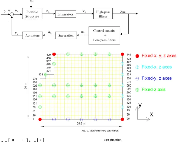
The problem tackled in this paper consists offinding the optimum locations and control gains of the AVC MIMO control strategy presented in[4]. This section explains the general scheme shown inFig. 1and how to formulate the cost function to use the CRO-SL as solver. In addition, the FEfloor structure model, the AVC design methodology and the optimization problem are also described in this section.
2.1. Floor structure
The structure considered in this paper is a dining roomfloor of a primary-secondary school sited in Madrid (Spain). The general ar-rangement of beams and pillars is shown inFig. 2. The FE model was created in ANSYS[43]using shell elements and 449 nodes. It is an irregular rectangular composite floor with the dimension of 25.5 m × 20 m × 0.3 m. As is shown inFig. 2, thefloor is supported by 33 columns. Different connections between thefloor and columns are marked with different colors: red1 ones represent those whose dis-placements in x, y and z directions are all restricted; cyan ones that are restricted in x and z displacements; blue ones that are restricted in y and z displacements; green ones are connections only restricted in z direc-tion. None of the connections between columns and deck are restricted in rotations. The yellow lines show the meshing grids of the shell ele-ments. The material properties considered are: modulus of elasticity
= ×
E 20 109N/m2, Poisson’s ratio ν=0.15and density ρ=3000kg/
m3. The density has been increased from 2500 kg/m3to 3000 kg/m3in
order to include a portion of the imposed load (approximately 30%) and the total dead load, following the recommedation of [44] for analysis of floor vibrations. The modal shapes, natural frequencies, damping ratios and modal masses of thefirst ten vibration modes can be seen inFig. 3.
For the sake of simplicity, theflexible structure and the integrators are grouped, so that the output of the resulting system isys, which is the velocity atqlocations. Thus, the standard state-space representation of the model for thisflexible structure (withnvibration modes,p actua-tors,qsensors andrperturbations) is represented as follows (seeFig. 1):
= + +
=
x A x B u B w
y C x
̇ ,
,
s s s s s s s
s s s
1 2
(1)
If Eq.(1)is defined in modal coordinates, the state-space matrices are as follows[45]:
= ⎡
⎣− − ⎤⎦ = ⎡⎣
⎤ ⎦ = ⎡
⎣ ⎤
⎦ =
A 0 I
Ω ZΩ B
0 Φ
B Φ0 C Φ 0
2 , ,
, [ ],
s s
u
s
w y
2 1
2
(2) in whichΩandZare, respectively, the diagonal matrices formed by the natural frequencies ([ω1, ,…ωn]) and the damping ratios ([ , , ]ξ1…ξn); and
the matricesΦ Φu, y andΦw are matrices with dimensionsn×p q, ×n
andn×r. It is important to highlight that eachkth column ofΦuand
Φwand each row ofΦyis formed by thekth vibration mode values at the
positions of the actuators (Φu), perturbations (Φw) and sensors (Φy),
respectively. The state vector is defined as: xs=[xs1, ,…x xsn, ̇ , , ̇ ]s1…xsn, where
[
xs1, ,…xsn]
are the modal coordinates of the structure, and…
[
ẋ , , ̇s1 xsn]
are their derivatives.2.2. AVC methodology
The AVC is implemented by using (seeFig. 1): (i) inertial actuators to generate the forces through the acceleration of inertial masses to the structure on which they are placed, (ii) second-order Butterworth high-passfilters to reduce the gain of the loop at low-frequencies, which can saturate the actuator, (iii) second-order Butterworth high-passfilters to reduce the gain of the loop at high-frequencies, reducing thus the risk of spillover problems[6], and (iv) force saturation blocks to simulate the maximum voltage inputs of the inertial actuators. Note that if the cut-offfrequencies of thefilters are separated from the vibration modes, the AVC can be approximated by a direct velocity feedback (DVF).
The AVC methodology consists of the two following main steps: (i) define the cut-offfrequencies of thefilters according to the vibration modes of the structure and to the bandwidth of the actuators and (ii) decide the locations ofpinertial actuators andqsensors (i.e., the values ofΦuandΦyin Eq.(2)) and tune the matrix gain in order to minimize a
cost function.
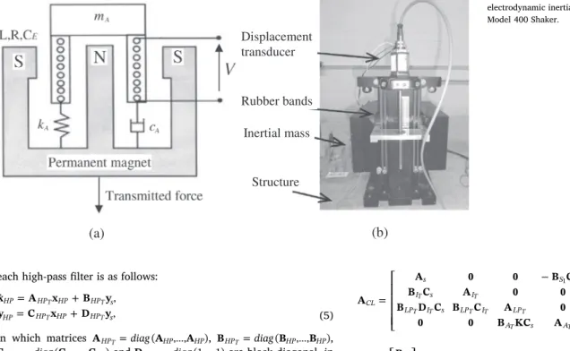
2.2.1. Actuator dynamics
The actuator consists of an inertial (or moving) massmAattached to
a current-carrying coil moving in a magneticfield created by an array of permanent magnets. The inertial mass is connected to the frame by a suspension system. The mechanical part is modelled by a spring stiff-nesskAand a viscous dampingcA. The electrical part is modelled by the
resistanceR, the inductance of the coilLand the voice coil constantCE,
which relates coil velocity and the back electromotive force (Fig. 4(a)) [46]. Combining the mechanical and the electrical part, the linear be-havior of the actuator can be closely described as a third-order dynamic model. Thus, the state space model of thepactuators is as follows:
̂
= +
=
x A x B u
y C x
̇ ,
,
A A A A A A A A
T T
T (3)
in which matrices AAT=diag(AA, ,…AA),BAT=diag(BA, ,…BA) and
=diag …
CAT (CA, ,CA)are block diagonal, in which matrices A BA, Aand
CAare defined as follows[47]:
= ⎡
⎣ ⎢ ⎢ ⎢
−
− +
− +
⎤
⎦ ⎥ ⎥ ⎥
=⎡ ⎣
⎢ ⎤
⎦
⎥ =
εω ω ξ ω ε
ε ξ ω g
A B C
0 0
1 0 ( 2 )
0 1 ( 2 )
, 0
0 , [0 0 1],
A
A
A A A
A A A
A A
2
2
(4)
in which the actuator is defined by gA>0, its damping ratioξAand natural frequencyωA. The value ofεmodels the low-pass properties of
the actuator. The actuator considered in this work is an APS Dynamics model 400 electrodynamic shaker, which is shown inFig. 4(b). The identified parameters of (4) are [47]: ωA=13.2rad/s (2.1 Hz),
=
gA 12,000andε=47.1.
Fig.1.Generalcontrolscheme.
2.2.2. Filters design
The cut-offfrequencies of the high-passfilters (denoted byωHP) is
the result of the tradeoffbetween the resonance frequency of actuator,
since small values ofωHPincrease the risk of stroke saturation, and the
first vibration mode of the structure, since higher values ofωHPreduce
the damping imparted by a DVF controller[4]. The state-space model of
1
stvibration mode
2
ndvibration mode
3
thvibration mode
4
thvibration mode
5
thvibration mode
6
thvibration mode
7
thvibration mode
8
thvibration mode
9
thvibration mode
10
thvibration mode
Modal mass: 45.4 tons
ω
1= 35.2 rad/s (5.6 Hz)
ξ
1= 1.00%
Modal mass: 47.3 tons
ω
2= 47.1 rad/s (7.5 Hz)
ξ
2= 0.97%
Modal mass: 44.6 tons
ω
3= 57.2 rad/s (9.1 Hz)
ξ
3= 1.00%
Modal mass: 44.6 tons
ω
4= 64.1 rad/s (10.2 Hz)
ξ
4= 1.04%
Modal mass: 47.5 tons
ω
5= 67.2 rad/s (10.7 Hz)
ξ
5= 1.05%
Modal mass: 46.9 tons
ω
6= 76.7 rad/s (12.2 Hz)
ξ
6= 1.12%
Modal mass: 30.3 tons
ω
7= 92.4 rad/s (14.7 Hz)
ξ
7= 1.24%
Modal mass: 46.9 tons
ω
8= 93.6 rad/s (14.9 Hz)
ξ
8= 1.25%
Modal mass: 45.5 tons
ω
9= 105.6 rad/s (16.8 Hz)
ξ
9= 1.35 %
Modal mass: 40.2 tons
ω
10= 111.8 rad/s (17.8 Hz)
ξ
10= 1.41 %
Fig. 3.Floor mode shapes, natural frequencies,
each high-passfilter is as follows:
= +
= +
x A x B y
y C x D y
̇ ,
,
HP HP HP HP s HP HP HP HP s
T T
T T (5)
in which matrices AHPT=diag(AHP, ,…AHP), BHPT=diag(BHP, ,…BHP),
=diag …
CHPT (CHP, ,CHP)andDHPT=diag(1, ,1)… are block diagonal, in whichAHP,BHPandCHPare defined as follows[48]:
= ⎡ ⎣
⎢−ω − ω ⎤⎦⎥ = ⎡⎣ ⎤⎦ = −ω − ω
A 0 1 B C
2 ,
0
1 , [ 2 ].
HP
HP2 HP HP HP HP HP
2
(6) The low-passfilters to avoid spillover problems[6]are defined as follows:
= +
=
x A x B y
y C x
̇ ,
,
LP LP LP LP HP
LP LP LP
T T
T (7)
in which matricesALPT=diag(ALP, ,…ALP),BLPT=diag(BLP, ,…BLP)and
=diag …
CLPT (CLP, ,CLP)are block diagonal, in whichALP,BLPandCLP
are defined as follows[48]:
= ⎡ ⎣
⎢−ω − ω ⎤⎦⎥ = ⎡⎣ ⎤⎦ = ω
A 0 1 B C
2 ,
0
1 , [ 0].
LP
LP2 LP LP LP LP
2
(8) The value ofωLP, which is the cut-offfrequency, must be sufficiently
high when compared with the maximum vibration mode frequency that may be controlled.
2.2.3. Sensor/actuator locations and gain matrix tuning
In addition to configuring the values ofΦuandΦy, which depend on
the position of thepactuators andqsensors, the control gain matrix must be tuned. This matrix, which is denoted by K, is defined in a general form as follows:
= ⎡ ⎣ ⎢ ⎢ ⎢ ⎢ ⋯ ⋯ ⋮ ⋮ ⋱ ⋮ ⋯ ⎤ ⎦ ⎥ ⎥ ⎥ ⎥
K K K
K K K
K K K
K ,
q q
p p pq
11 12 1
21 22 2
1 2 (9)
in whichKijis the control gain applied at control inputidue to control
outputj.
Therefore, the state equation of the closed-loop system is obtained fromFig. 1and Eqs.(1)–(9), and results in
= +
ẋCL A xCL CL B wCL s, (10)
= +
ys C xCL CL D wCL s,
where the state vector isxCL=[ , ,x x xs I LP,xA]and the state matrices are:
= ⎡ ⎣ ⎢ ⎢ ⎢ ⎢ − ⎤ ⎦ ⎥ ⎥ ⎥ ⎥ A
A 0 0 B C
B C A 0 0
B D C B C A 0
0 0 B KC A
,
CL
s S A
I s I
LP I s LP I LP
A s A
T
T T
T T T T T
T T 1 (11) = ⎡ ⎣ ⎢ ⎢ ⎢ ⎤ ⎦ ⎥ ⎥ ⎥ = − = B B 0 0 0
C C A 0 0 B C D B
, [ , , , ] and .
CL s
CL s s s AT CL s
1
1 1
The sensor/actuator locations and gain matrix tuning consider the human vibration perception. This perception depends on the direction of incidence to the human body, the frequency content of the vibration (for given amplitude) and the duration of sustained vibration, among other factors. The frequency sensitivity variation for a body position can be taken into account by attenuating or enhancing the system sponse for frequencies where perception is less or more sensitive, re-spectively. The degree to which the response is attenuated or enhanced is referred to as frequency weighting. Thus, frequency weighting functions are applied in order to account for the different acceptability of vibrations for different directions and body positions. ISO 2631[5] provides details for frequency and direction weighting functions that can be applied, which are all based on the basicentric coordinate system shown in Fig. 5. These have been included in current floor design guidelines such as the SCI guidance[44]. According to ISO 2631, for z-axis vibration and standing and seating, the frequency weighting function (Wk) is afilter with the frequency response shown inFig. 6.
Human comfort under vibration is also related to the duration of sustained vibration[51]. Thus, persistent vibrations should be pena-lised in the control design, giving more importance to transient vibra-tion of long-duravibra-tion than those of short-duravibra-tion. This is taken into account by multiplying the system response by an exponential time weighting (i.e.,eαt), whereα>0adds a constraint in the relative
sta-bility of the controlled system. Note that persistent states are penalised more heavily asαis increased. The value ofαassumed in this work is the relative stability for the closed-loop system whenK=0, which is defined by min (i ξ ωi i)=ξ ω1 1=0.3547. Note that even the
worst-de-signed controller would be able to increase the relative stability, in other words, the real part of any eigenvalue ofACLmust be less than
−0.3547.
Thus, the human vibration perception is considered in the controller design by weighting the state vector of the structurexs(see Eq.(11)) as
follows:
= ∗ ∈ …
xsWl (e xαt sl( ))t gFW( ),t l [1, ,2 ],n (12)
where (∗) denotes the convolution process and gFW( )t is the impulse
(a)
(b)
Displacement
transducer
Rubber bands
Inertial mass
Structure
response function of a system with the frequency response function shown in Fig. 6. Note that the weighted vector xsW is only used to calculate the PI used to derive the optimal sensor/actuator locations and the gain matrix. In other words, the weighting functions are not included into the closed-loop system ofFig. 1and into the Eqs.(10) and (11).
2.3. Optimization problem
The optimization problem consists of minimizing the following functional:
∫
=
{
}
g( )z max 1 x z Qx z t
2 ( ) ( )d ,
t sw T
sw
0
f
(13)
byfinding the optimal parameters ofz=[ , ]K Λ, where the matrixQis a ×
n n
2 2 positive definite matrix, which is taken as[3]
= ⎡
⎣ ⎢ ⎢ ⎢ ⎢ ⎢ ⎢ ⎢ ⎢
⋯ ⋯
⋮ ⋱ ⋮ ⋮ ⋱ ⋮
⋯ ⋯
⋯ ⋯
⋮ ⋱ ⋮ ⋮ ⋱ ⋮
⋯ ⋯
⎤
⎦ ⎥ ⎥ ⎥ ⎥ ⎥ ⎥ ⎥ ⎥
ω ϕ
ω ϕ ϕ
ϕ
Q
0 0 0
0 0 0
0 0 0
0 0 0
,
n n
n
12 1,max 2
2 ,max 2
1,max 2
,max 2
(14)
in whichϕk,max is the maximum value of thektheigenvectorϕ k. Note
that the displacement states are weighted by the natural frequencies, thus making the displacement states comparable to velocity states. The variableΛcontains the locations of a set ofpactuators andqsensors (i.e.,Λis a vector ofp=qcomponents, whose values indicate the node number where each pair sensor/actuator is placed). Finally, the value of
tf is the simulation time to obtain the PI, which must be large enough to
achieve the steady state ofg( )z (i.e., the weighted state vectorxsW≅0). Note that the problem offindingz=[ , ]K Λ, which minimizesg( )z is a hard optimization problem, in which traditional optimization
Fig.5.DirectionsforvibrationaccordingtoISO2631
[5].
methods (gradient-based approaches or similar) cannot be applied due to the problem’s characteristics (for example,g( )z cannot be obtained analytically).
3. Proposed co-evolution Coral Reefs Optimization with Substrate Layer
This section presents the CRO-SL proposed in this paper for tackling the MIMO AVC design. First, the basic CRO algorithm is presented, which will be modified with a substrate layer in order to obtain a competitive co-evolution algorithm with different exploration proce-dures involved.
3.1. Basic CRO
The CRO[52,53] is an evolutionary-type algorithm based on the behavior of the processes occurring in a coral reef. LetR be the reef represented by anR1×R2grid, where each position( , )i j ofRis able to allocate a coral or a colony ofcorals(Ci j,), i.e., tentative solutions to the current optimization problem at hand. Therefore, a coral encodes a candidate solution to the optimization problem. In our specific ap-proach, this solution is encoded as a real-valued vector that represents the parameters of the AVC (zin Eq.(13)). The quality of a solution is evaluated using the objective function given in Section2.3.
The CRO algorithmfirst initializes some random positions ofRwith random corals, and leaves some other positions empty. These holes in the reef are available to host new corals that will be able to freely settle and grow in later phases of the algorithm. The rate between free/oc-cupied positions inR at the beginning of the algorithm is a parameter of the CRO algorithm, denoted asρ0with0<ρ0<1.
The second phase simulates the processes of reproduction and reef formation. The different reproduction mechanisms available in nature are recreated by sequentially applying different operators:
1.External sexual reproduction or Broadcast Spawning.Broadcast spawning consists of the following steps at each iterationkof the algorithm:
1.a. A random fraction of the existing corals is selected uniformly, turning these corals into broadcast spawners. The fraction of broadcast spawners with respect to the overall amount of ex-isting corals in the reef will be denoted asFb.
1.b. Several coral larvae are formed. To generate each new larva, two broadcast spawners are selected and a crossover operator or any other exploration strategy is applied. Note that once two corals have been selected to be the parents of a larva, they are not chosen anymore at iterationkfor reproduction purposes. Corals’selection can be done randomly, uniformly, or using any fitness proportionate selection approach (e.g. roulette wheel). 2.Internal sexual reproduction or Brooding.Hermaphrodite corals
mainly reproduce by brooding. This reproduction is modelled by means of any kind of mutation mechanism and takes place on a fraction of corals of1−Fb. A percentagePiof the coral is mutated.
3.Larvae setting.Once the larvae are formed either through external or internal reproduction, they will try to set and grow in the reef. Each larva will randomly try to set in a position( , )i j of the reef and, if the location is free, it will set. If the location is already occupied, the new larva will set only if its health function (fitness) is better than that of the existing coral. Moreover, the CRO algorithm defines a parameterηthat determines the maximum number of tries a larva can attempt at each iterationh.
4.Asexual reproduction.Corals reproduce asexually by budding or fragmentation. The CRO models this mechanism in the following way: the whole set of corals in the reef are sorted according to their level of health value (given by f(Cij)). Then, a small fraction (de-noted asFa) of the available corals are duplicated and mutated (with
probabilityPa) to provide variability, and try to settle in a different
part of the reef as in Step 3.
5.Depredation.Corals may die during the reef’s formation. Therefore, at the end of each reproduction iterationk, a small number of corals in the reef can be depredated, thus liberating space in the reef for next coral generation (iterationh+1). The depredation operator is applied with a very small probability (Pd) to a fraction (Fd) of the
corals in the reef with worse health.
Algorithm 1illustrates theflowchart diagram of the CRO algorithm, with the different CRO phases (reef initialization and reef formation), along with all the operators described above.
Algorithm 1.Pseudo-code for the CRO algorithm.
Require:Valid values for the parameters controlling the CRO algorithm
Ensure:A single feasible individual with optimal value of itsfitness
1: Initialize the algorithm
2:foreach iteration of the simulationdo 3: Update values of influential variables:
predation probability, etc. 4: Sexual reproduction processes
(broadcast spawning and brooding) 5: Settlement of new corals
6: Predation process
7: Evaluate the new population in the coral reef 8:end for
9: Return the best individual (final solution) from the reef
3.2. CRO with substrate layer (CRO-SL)
The original CRO algorithm described above is based on the main processes of coral reproduction and reef formation that occur in nature. However, there are many more interactions in real reef ecosystems that can be also modelled and incorporated into the CRO approach to im-prove its performance in optimization and search problems. For ex-ample, different recent studies have shown that successful recruitment in coral reefs (i.e., successful settlement and subsequent survival of larvae) strongly depends on the type of substrate on which they fall after the reproduction process[54]. This specific characteristic of coral reefs wasfirst included in the CRO in[55], in order to solve different instances of the Model Type Selection Problem for energy applications. This new version of the CRO was named CRO-SL (Coral Reefs Optimi-zation algorithm with Substrate Layer). In[42], a new version of the CRO-SL was presented, where several substrate layers which provide a different search procedure each, were defined in the CRO. Following this version of the algorithm, the CRO-SL general approach for com-petitive co-evolution, where each substrate layer represents different processes (different models, operators, parameters, constraints, re-pairing functions, etc.). The use of CRO-SL as a competitive co-evolu-tion algorithm, was successfully tested in different applicaco-evolu-tions and problems such as micro-grid design [56], vibration cancellation in buildings[57]or in the evaluation of novel non-linear search proce-dures[58]. In this section, the main ideas of the CRO-LS as co-evolution search algorithm are described, which will be applied to solve the problem of AVC design.
by indicating which structure (search operator in this case) is associated with the cell (i,j) of the reef. Each coral in the reef is then processed in a different way (with a different search operator) depending on the specific substrate layer in which it falls after the reproduction process. Note that this modification of the basic algorithm does not imply any change in the corals’encoding.Fig. 7shows an example of the CRO-SL reefs structure, with five different substrate layers. In this example, each substrate is assigned to a different exploration process, Harmony Search (HS), Differential Evolution (DE), Gaussian mutation, 1-point crossover and 2-points crossover.
The CRO-SL can be seen as a generalization of the original CRO, that does not modify the dynamics of the algorithm, which can still follow the basic steps given in the previous subsection. The only difference between the CRO-SL and the basic CRO is the specific implementation of the broadcast spawning procedure, which now depends on the spe-cific substrate to which each coral (solution) is associated. Note that the CRO-SL is in fact a competitive co-evolution searching procedure: the substrate layers of the CRO-LS promote the co-evolution process be-tween different search operators, without the necessity of defining different populations. The competitiveness of the approach is given by the fact that CRO dynamics is based on a procedure of larvae settlement which involves competition among corals.
4. Computational evaluation and comparisons
The examples carried out to evaluate the proposed CRO-SL in this context consist of two approaches of AVC, a SISO and a MIMO cases, where MIMO is configured with p = q = 2 (each pair is placed at same location).
The CRO-SL parameters used in the experiments are shown in Table 1.
Five different substrates layers have been used within the CRO-SL in the experiments carried out:
1. HS: Mutation from the Harmony Search algorithm. Harmony Search [35] is a population based meta-heuristic that mimics the im-provisation of a music orchestra while its composing a melody. This method integrates concepts such as harmony aesthetics or note pitch
as an analogy for the optimization process, resulting in a good ex-ploratory algorithm. This property is also applicable to the operator based on its behavior. HS controls how new larvae are generated in one of the following ways: (i) with a probability HMCR∈[0,1]
(Harmony Memory Considering Rate), the value of a component of the new larva is drawn uniformly from the same values of the component in the other corals. (ii) with a probability PAR∈[0,1]
(Pitch Adjusting Rate), subtle adjustments are applied to the values of the current larva, replaced by any of its neighboring values (upper or lower, with equal probability).
2. DE: Mutation from Differential Evolution algorithm (withF=0.6). This operator is based on the evolutionary algorithm with the same name[59], a method with powerful global search capabilities. DE introduces a differential mechanism for exploring the search space. Hence, new larvae are generated by perturbing the population members using vector differences of individuals. Perturbations are introduced by applying xi′ =xi1+F x( i2−xi3) for each encoded
parameter on a random basis.x′corresponds to the output larva,xt
are the considered parents (chosen uniformly among the popula-tion), andFdetermines the evolution factor weighting the pertur-bation amplitude.
3. 2Px: Classical 2-points crossover. The crossover operator is the most classical exploration mechanism in genetic and evolutionary algo-rithms[9]. It consists of coupling to individuals at random, choosing two points for the crossover, and interchanging the genetic material in-between both points. In the CRO-SL, one individual to be crossed is from the 2Px substrate, whereas the couple can be chosen from any part of the reef.
4. MPx: Multi-points crossover. Similar to the 2-points crossover, but in this case a numberkof crossover points are selected, and a binary template decides whether parts of the individuals are interchanged. 5. GM: Gaussian Mutation, with aσ value linearly decreasing during the run, from0.2·(A B− )to0.02·(A B− ), where[ , ]B A is the domain search. Specifically, the Gaussian probability density function is:
= −
f x
σ πe
( ) 1
2 .
G σ
x σ
(0,2) 2
2 2
The reason of adapting the value ofσ along the generations is to provide a stronger mutation in the beginning of the optimization, whilefine tuning with smaller displacements nearing the end. The mutated larva is thus calculated as:xi′ =xi+δNi(0,1), whereNi(0,1)
is a random number following the Gaussian distribution.
Note that the linear state-space system defined in Eqs.(10) and (11) does not include the nonlinear actuator limitations in the stroke and voltage. It is the main reason why the computational strategy defined in [3] cannot be applied when practical considerations are included. Therefore, since the value of g( )z (see Eq.(13)) cannot be obtained analytically, the general control scheme ofFig. 1is simulated in SI-MULINK©. In order to compute this PI, a system disturbance must be defined. Note that the design of optimal controllers for unknown dis-turbances is not trivial, since prescribed disdis-turbances are needed within the design process. The solution adopted in this work, similar to that used in[3], is to approximate the influence of zero initial conditions and a spatially distributed, but temporally impulsive, disturbance force by an appropriate initial condition and zero disturbance force. This is achieved by assigning a non-zero initial condition to the velocity states of the structure. Thus, the system disturbance is then defined as
= … x …x
xs(0) [0, ,0, ̇ (0), , ̇ (0)]s1 sn , where each value ofẋ (0)sk is obtained as follows:
=
ẋ (0)sk F ϕ0 k,max, (15)
whereF0represents the impulse load value applied to a particular vi-bration mode. Note that the impulsive force is applied to the point of maximum amplitude of each vibration mode, creating thus an extreme
HS DE 1-Point
Crossover Gaussian
mutation
2-Points Crossover
Fig. 7.Example of different substrate layers in a CRO-SL algorithm.
Table 1
Parameters values used in the CRO-SL.
Parameter Description Value
Reef Reef size 120
Fb Frequency of broadcast spawning 97%
Substrates HS, DE, 2Px, MPx, GM 5
Natt Number of tries for larvae settlement 3
Fa Percentage of asexual reproduction 5%
Fd Fraction of corals for depredation 5%
Pd Probability of depredation 5%
scenario for the initial disturbance. It is expected that the control system will perform successfully under other loading conditions. The value ofF0used in this work is 100 N, which excites the structure to achieve high acceleration level at some structures nodes that can be reduced by one or two commercial shakers (showed inFig. 4).
The design parameters, which are not optimized by CRO-SL, are: (i) =
ωHP 12.6rad/s (2 Hz), (ii)ωLP=125.6rad/s (20 Hz), (iii) stroke and
voltage saturation of the actuator APS Dynamics Model 400 Shaker, which are 7.9 mm and 2 V, respectively, and (iv)α=0.3547(see Eq. (12)).
4.1. Results
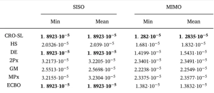
Table 2shows the results obtained by the proposed CRO-SL, com-pared to different alternative algorithms. Specifically, all the algorithms which form the substrate layers in the CRO-SL approach have been tried on their own: the CRO with a single substrate has been run, with the same number of function evaluations than in the case offive substrates. This will show how the competitive co-evolution process promoted by the CRO-SL is able to obtain accurate solutions for the AVC design and location problem. In addition, a comparison with a high-performance recently proposed meta-heuristics for structures optimization, the En-hanced Colliding Bodies Optimization (ECBO) [49]is included. This approach is an improved version of the CBO [39], which includes memory and a specific mechanism to scape from local optima. The computer code for the ECBO[50]has been released by the authors in order to implementation it with small adaptations to the problem at hand. InTable 2it can be seen how the CRO-SL (five substrates) obtain the best performance, both in the SISO and MIMO cases, with two ac-tuators/sensors (p=q=2). In the SISO case, the differences among
different methods are small, since it is the simplest case. In fact, the CRO-SL and CRO with DE substrate and the ECBO algorithm obtain a similar value of the PI. In this case, the HS substrate is the next algo-rithm in terms of performance, whereas the Gaussian mutation and the two crossover operators (2-points and multi-point) are the poorest in terms of the PI. In the case of the MIMO, the differences are much more significant. The CRO-SL with five substrates in co-evolution clearly obtains the best performance. The ECBO algorithm also performs well in this problem, as it obtains the second best result overall. In this case, the DE, is the third best approach among the tested algorithms. The HS is also the next better substrate in this version of the problems, and again the Gaussian and crossover operators do not obtain competitive results on their own in this case.
Fig. 8shows the ratio of times that every substrate generates the best larva per generation in the CRO-SL approach. It is possible to see how the 2-points crossover and the MPx crossover are the two ex-ploration operators that contribute the most to the CRO-SL search. The contribution of the DE substrate is also significant, and it grows during the search. Note that the HS and Gaussian substrates are the ones which contribute the less to the search, especially, the Gaussian substrate does
not seem to be effective in this problem, and barely contributes to ob-tain the best solutions in each iteration of the CRO-SL.
Following, the best solutions obtained by the CRO-SL algorithm in the SISO and MIMO cases is analyzed in detail. The best result obtained by the CRO-SL for the SISO case (also reached by ECBO and DE) is the following:
=
K 4758.6, (16)
=
= × −
g
Λ z
329,
( ) 1.8923 10 .5
This design is useful to reduce the vibration of the 1st, 2nd, 5th, 7th and 9th modes. Note that the frequency weighting functionWkofFig. 6
shows that the modes with natural frequency higher than 10 Hz are less important from the human perception point of view. Then, this SISO control is mainly designed for 1st, 2nd and 5th mode. The location of the actuator/sensor pair is shown inFig. 9(triangle). This point is a location where these three vibration modes can be measured and con-trolled.
The best result obtained by the CRO-SL for the MIMO case (best solution over all comparison algorithms) is the following:
= ⎡
⎣ ≅ ⎤⎦
K 1272.5 1367.8
0 3753.2 , (17)
=
= × −
g
Λ z
[83 328], ( ) 1.282 10 .5
The two actuator/sensor pairs are shown inFig. 9(hexagons). The first actuator/sensor location is practically the same as SISO design (node 328). The second actuator/sensor pair is useful to reduce the vibration of the 3rd, 4th, 6th, 8th and 10th mode. However, if the human perception is considered, the actuator placed at node 83 is mainly focused on 3rd and 4th mode. Therefore, this MIMO design can reduce the vibration of thefirst five vibration modes, all which can influence the human comfort. It should be also remarked that the op-timum matrix gainKconfigures thefirst actuator as a two inputs - one output system, whereas the second actuator is configured as a decen-tralized collocated control system. Therefore, although the actuator/ sensor locations may be obvious, since MIMO AVC reduces the vibra-tion level of thefirstfive vibration modes, the configuration ofK to-gether with the problem of actuator/sensor locations cannot be solved with traditional control design tuning methods. Finally, the value of PI is reduced 32.25% with respect to the SISO case (seeTable 2).
The performance of both controllers (SISO and MIMO) is also tested by exciting the structure with heel-drop and jumping inputs. These two perturbations are representative examples of impulsive (heel-droop allows measuring the damping imparted by controllers, evaluating the transient response evaluation offloor structures and checking stability properties) and periodic (jumping is a rhythmic human activity, such as dancing or aerobics) loads, which can be generated by humans.
The performance of both controllers tested with heel-drop excita-tion is shown by comparing the peak acceleraexcita-tion and settling time. The force of the heel-drop is modelled by a ramp with initial value of 2670 N and 50 ms of duration. The settling time is defined as the time taken for the response to fall and remain within some specified per-centage of the maximum peak value of the acceleration response. For the sake of simplicity, here it is calculated as the time taken for the acceleration response to fall and remain within the range of 0.005 m/s2.
The same nodes are chosen (excitation nodes are 82, 88, 327, 355 and 360, monitoring nodes are 333 and 90).
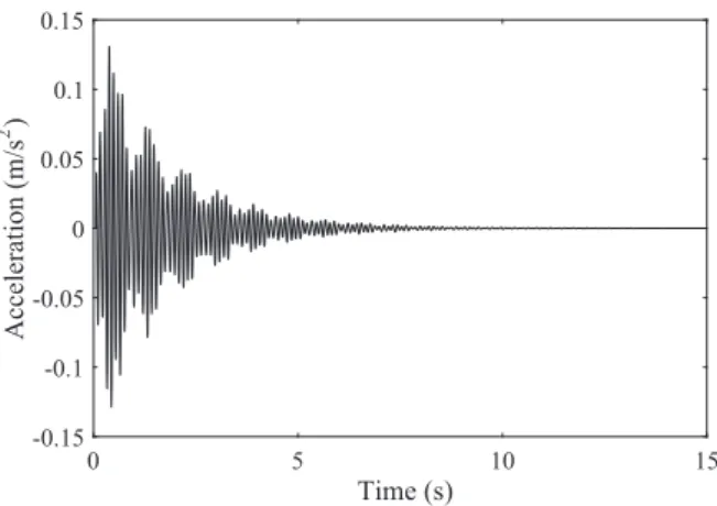
Figs. 10–12show the simulated time response of node 333 for the uncontrolled case, the SISO AVC of Eq.(16)and the MIMO AVC of Eq. (17). Note that the vibration reduction level is practically the same for SISO and MIMO AVC at node 333 since the peak acceleration is 0.132 m/s2for SISO and 0.130 m/s2for MIMO, while the settling time
is 1.985 s for SISO and 1.865 s for MIMO.
Table 2
Comparison of the results obtained in the two case-studies taken into account (SISO and MIMO) with different algorithms, in terms of thefitness function considered (Eq.(13)).
SISO MIMO
Min Mean Min Mean
CRO-SL 1 8923 10. · −5 1 8923 10. · −5 1 282 10. · −5 1 2835 10. · −5
HS 2.0326·10−5 2.039·10−5 1.681·10−5 1.832·10−5
DE 1 8923 10. · −5 1 8923 10. · −5 1.4199·10−5 1.5431·10−5
2Px 3.2173·10−5 3.2205·10−5 2.3401·10−5 2.3491·10−5
GM 2.5513·10−5 2.5698·10−5 2.2238·10−5 2.2549·10−5
MPx 3.2155·10−5 3.2304·10−5 2.3375·10−5 2.3577·10−5
Figs. 13–15show the simulated time response of node 90 for the three cases. Note that, unlike node 333, the vibration reduction level is significant if SISO and MIMO AVC are compared since the peak accel-eration is 0.129 m/s2 for SISO and 0.104 m/s2for MIMO, while the settling time is 4.625 s for SISO and 2.979 s for MIMO. Therefore, the MIMO AVC improves substantially the vibration reduction.
For the jumping excitation, a pedestrian of weight 800 N is con-sidered and the dynamic load factors (amplitude of each harmonic) of the excitation proposed in[60]are assumed (the periodic excitation is represented as a Fourier serie). Five nodes (82, 88, 327, 355 and 360) are chosen to excite with (seeFig. 9) with these frequencies: (i) 2.8 Hz– Node 355-1st vibration mode (5.6 Hz), (ii) 2.5 Hz–Node 360-2nd vi-bration mode (7.5 Hz), (iii) 3.0 Hz – Node 88-3rd vibration mode (9.1 Hz), (iv) 3.4 Hz–Node 82-4th vibration mode (10.2 Hz) and (v)
3.6 Hz–Node 327-5th vibration mode (10.7 Hz).
The performance is evaluated using the vibration dose value (VDV), also known as fourth power vibration dose method, which is used to provide information about the serviceability of thefloor for rhythmic activities[44]. The VDV of all nodes on thefloor during 60 s of jumping excitation is calculated. Fig. 16 shows the percentage of floor area where a VDV value (x-axis) is exceeded. It can be seen that MIMO achieves a significant improvement respect to SISO when the VDV is higher or equal to 0.02 m/s1.75. This improvement is due to the fact that
SISO cannot cancel the vibration of 3rd and 4th vibration modes. In addition, MIMO AVC can eliminate the vibration higher than 0.03 m/ s1.75. Therefore, it can be concluded that a MIMO AVC may be
neces-sary when a SISO AVC cannot guarantee that the vibration level does not exceed a maximum.
0 5 1 0
0 1 0
5 0
Generations
0 10 20 30 40 50 60 70 80 90 100
]
%[
oit
a
R
HS DE 2Px GM MPx
Fig. 8.Ratio of times that each substrate produces the best larva in each iteration of the CRO-SL algorithm, for the AVC-MIMO design.
SISO node 329 MIMO
node 328
MIMO node 83
Excitation node 327
Excitation node 355
Excitation node 360
Excitation node 82
Excitation node 88
Response node 333
Response node 90
5. Conclusions
In this paper, the recently proposed Coral Reefs Optimization al-gorithm with Substrate Layer (CRO-SL) has been applied to a problem of active vibration control (AVC) design for human-induced vibration mitigation in civil structures. The CRO-SL is a competitive co-evolution meta-heuristic algorithm in which different exploration procedures (i.e., different types of searching mechanisms) are jointly evolved within a single population of potential solutions to the problem. The
CRO-SL algorithm gives the possibility of jointly exploring the perfor-mance of different meta-heuristics within a single population. A state-of-the-art operators in the CRO-SL, such as two-points crossover mu-tations, Harmony Search, Differential Evolution or Gaussian mutations is included. In addition, a comparison with a recently proposed meta-heuristic for structures design, the Enhanced Colliding Bodies Optimization algorithm is also presented. In terms of structural design, the main contribution of this paper is to have the possibility of Time (s)
0 5 10 15
Acceleration (m/s
2 )
-0.15 -0.1 -0.05 0 0.05 0.1 0.15
Peak acceleration = 0.145 m/s2 Settling time = 8.512 s
Fig. 10.Simulated time response without AVC of node 333 for a normalized heel-drop excitation at nodes 82, 88, 327, 355 and 360.
Time (s)
0 5 10 15
Acceleration (m/s
2 )
-0.15 -0.1 -0.05 0 0.05 0.1
0.15Peak acceleration = 0.132 m/s
2 Settling time = 1.985 s
Fig. 11.Simulated time response with SISO AVC of node 333 for a normalized heel-drop excitation at nodes 82, 88, 327, 355 and 360.
Time (s)
0 5 10 15
Acceleration (m/s
2 )
-0.15 -0.1 -0.05 0 0.05 0.1
0.15Peak acceleration = 0.130 m/s
2 Settling time = 1.865 s
Fig. 12.Simulated time response with MIMO AVC of node 333 for a normalized heel-drop excitation at nodes 82, 88, 327, 355 and 360.
Time (s)
0 5 10 15
Acceleration (m/s
2 )
-0.15 -0.1 -0.05 0 0.05 0.1 0.15
Peak acceleration = 0.131 m/s2 Settling time = 5.504 s
Fig. 13.Simulated time response without AVC of node 90 for a normalized heel-drop excitation at nodes 82, 88, 327, 355 and 360.
Time (s)
0 5 10 15
Acceleration (m/s
2 )
-0.15 -0.1 -0.05 0 0.05 0.1
0.15Peak acceleration = 0.129 m/s
2 Settling time = 4.625 s
Fig. 14.Simulated time response with SISO AVC of node 90 for a normalized heel-drop excitation at nodes 82, 88, 327, 355 and 360.
Time (s)
0 5 10 15
Acceleration (m/s
2 )
-0.15 -0.1 -0.05 0 0.05 0.1
0.15Peak acceleration = 0.104 m/s
2 Settling time = 2.979 s
designing a multi-input multi-output (MIMO) AVC for complex floor structures with several closely frequency space vibration modes, where the number of test points and sensor/actuator pairs is not a problem to obtain a global optimum solution in a affordable computation time. This paper also shows that a MIMO-AVC improves substantially the vibration reduction compared with a single-input and single output AVC for the proposed application example, which is a real complex floor structure. Future works will be focused on including new high-performance substrates in the CRO-SL, such as the ECBO compared in this work, and also on the application of this work to experimentally reduce human-induced vibration in real complexfloors by using inertial mass actuators.
Acknowledgements
This work has been partially supported by the Spanish Government under the projects numbers TIN2014-54583-C2-2-R, BIA2011-28493, DPI2013-47441 and BIA2014-59321, and by Comunidad Autónoma de Madrid, under project number S2013ICE-2933_02 supported by the Chinese Government.
References
[1] Ebrahimpour A, Sack RL. A review of vibration serviceability criteria forfloor structures. Comput Struct 2005;83(28–30):2488–94.
[2] Hudson MJ, Reynolds P. Implementation considerations for active vibration control in the design offloor structures. Eng Struct 2012;44:157–66.
[3] Hanagan LM, Kulasekere EC, Walgama KS, Premaratne K. Optimal placement of actuators and sensors forfloor vibration control. J Struct Eng 2000;126(12):1380–7. [4] Pereira E, Díaz IM, Hudson EJ, Reynolds P. Optimal control-based methodology for
active vibration control of pedestrian structures. Eng Struct 2014;80:153–62. [5] ISO 2631-1: Mechanical Vibration and shock- Evaluation of human exposure to
whole-body vibration- Part 1- General Requirements; 1997.
[6] Griggs WM, Anderson BD, Lanzon A. A“mixed”small gain and passivity theorem in the frequency domain. Syst Control Lett 2007;56(9–10):560–96.
[7] Saka MP, Hasancebi O, Geem ZW. Metaheuristics in structural optimization and discussions on harmony search algorithm. Swarm Evol Comput 2016;28:88–97. [8] Glover F, Kochenberg GA. Handbook of metaheuristics. New York, USA: Kluwer
Academic Publisher; 2003.
[9] Eiben AE, Smith JE. Introduction to evolutionary computing. Berlin: Springer-Verlag; 2003.
[10] Beyer HG, Schwefel HP. Evolution strategies–a comprehensive introduction. Nat Comput 2002;1(1):3–52.
[11] Yao X, Liu Y, Lin G. Evolutionary programming made faster. IEEE Trans Evol Comput 1999;3(2):82–102.
[12] Storn R, Price K. Differential evolution–a simple and efficient heuristic for global optimization over continuous spaces. J Global Optim 1997;11:341–59. [13] Dorigo M, Maziezzo V, Colorni A. The ant system: optimization by a colony of
cooperating ants. IEEE Trans Syst Man Cybern B 1994;26(1):29–41. [14] Kephart JO. A biologically inspired immune system for computers. Proc. of the
artificial life IV: the fourth international workshop on the synthesis and simulation of living systems. MIT Press; 1994. p. 130–9.
[15] Kennedy J, Eberhart RC. Particle swarm optimization. In: Proc. IEEE international conference on neural networks, vol. IV; 1995. p. 1942–8.
[16] Karaboga D, Basturk B. On the performance of the artificial bee colony (ABC)
algorithm. Appl Soft Comput 2008;8:687–97.
[17] Rashedi E, Nezamabadi-pour H, Saryazdi S. GSA: a gravitational search algorithm. Inf Sci 2009;179:2232–48.
[18] Mehrabian AR, Lucas C. A novel numerical optimization algorithm inspired from weed colonization. Ecol Inform 2006;1:355–66.
[19] Oftadeh R, Mahjoob MJ, Shariatpanahi M. A novel meta-heuristic optimization algorithm inspired by group hunting of animals: hunting search. Comput Math Appl 2010;60(7):2087–98.
[20] Simon D. Biogeography-based optimization. IEEE Trans Evol Comput 2008;12(6):702–13.
[21] Cortés P, García JM, Onieva L. Viral systems: a new bio-inspired optimisation ap-proach. Comput Oper Res 2008;35(9):2840–60.
[22] Müller S, Airaghi S, Marchetto J. Optimization based on bacterial chemotaxis. IEEE Trans Evol Comput 2002;6(1):16–29.
[23] Passino KM. Biomimicry of bacterial foraging for distributed optimization and control. IEEE Control Syst Mag 2002;22:52–67.
[24] Yang XS, Deb S. Cuckoo search via Lévyflights. In: Proc. of the world conference on nature & biologically inspired computing; 2009. p. 210–4.
[25] Yang XS. A new metaheuristic bat-inspired algorithm. Proc Nat Inspired Cooper Strateg Optim Stud Comput Intell 2010;284:65–74.
[26] Kaveh A, Dadras A. A novel meta-heuristic optimization algorithm: thermal ex-change optimization. Adv Eng Softw 2017;110:69–84.
[27] Rajeev S, Krishnamoorthy CS. Discrete optimization of structures using genetic al-gorithms. ASCE J Struct Eng 1992;118:1233–50.
[28] Soh CK, Yang J. Fuzzy controlled genetic algorithm search for shape optimization. ASCE J Comput Civil Eng 1996;10:143–50.
[29] Togan V, Daloglu AT. Optimization of 3D trusses with adaptive approach in genetic algorithms. Eng Struct 2006;28(7):1019–27.
[30] Yan G, Zhou L. Impact load identification of composite structure using genetic al-gorithms. J Sound Vib 2009;319(3–5):869–84.
[31] Simonetti HL, Almeida VS, de Oliveira Neto L. A smooth evolutionary structural optimization procedure applied to plane stress Problem. Eng Struct
2014;75:248–58.
[32] Deb K. Optimal design of a welded beam via genetic algorithms. AIAA J 1991;29(11):2013–5.
[33] Kaveh A, Zolghadr A. Democratic PSO for truss layout and size optimization with frequency constraints. Comput Struct 2014;130:10–21.
[34] Schutte JF, Groenwold AA. Sizing design of truss structures using particle swarms. Struct Multidiscip Optimiz 2003;23(4):261–9.
[35] Geem ZW, Kim JH, Loganathan GV. A new heuristic optimization algorithm: har-mony Search. Simulation 2001;76(2):60–8.
[36] Rao RV, Savsani VJ, Vakharia DP. Teaching-learning-based optimization: a novel method for constrained mechanical design optimization problems. Comput Aided Des 2011;43:303–15.
[37] Degertekin SO, Hayalioglu MS. Sizing truss structures using teaching-learning based optimization. Comput Struct 2013;119:177–88.
[38] Kaveh A, Mahdavi VR. Optimal design of structures with multiple natural frequency constraints using a hybridized BB-BC/Quasi-Newton algorithm. Periodica Polytech
–Civ Eng 2013;57:1–12.
[39] Kaveh A, Mahdavi VR. Colliding bodies optimization: a novel meta-heuristic method. Comput Struct 2014;139:18–27.
[40] Kaveh A Khayatazad M. A new meta-heuristic method: ray optimization. Comput Struct 2012;112:283–94.
[41] Kaveh A, Talatahari SA. Novel heuristic optimization method: charged system search. Acta Mech 2010;213:267–89.
[42] Salcedo-Sanz S, Camacho-Gómez C, Molina D, Herrera F. A coral reefs optimization algorithm with substrate layers and local search for large scale global optimization. In: Proc. of the IEEE conference on evolutionary algorithms, Vancouver, Canada; 2016. p. 1–8.
[43] ANSYS Multiphysics. Release 10.0. Help System, Ansys Elements Reference, ANSYS, Inc.
[44] Smith AL, Hicks SJ, Devine PJ. Design offloors for vibration: a new approach
Fig.16.PercentageoffloorareawhereVDVis
(P354). The Steel Construction Institute; 2007.
[45] Gawronski WK. Advanced structural dynamics and active control of structures. Mechanical engineering series. Springer Link; 2004.
[46] Preumont A. Vibration control of active structures, solid mechanics and its appli-cations. Spring Link; 2011.
[47] Díaz IM, Reynolds P. Acceleration feedback control of human-inducedfloor vi-brations. Eng Struct 2010;32(1):163–73.
[48] Middlehurst R, Jack/Harrison. Practicalfilter design. Prentice-Hall Inc.; 1993. [49] Kaveh A, Ilchi Ghazaan M. Enhanced colliding bodies optimization for design
problems with continuous and discrete variables. Adv Eng Softw 2014;77:66–75. [50] Kaveh A, Ilchi Ghazaan M. Computer codes for colliding bodies optimization and its
enhanced version. Int J Optimiz Civil Eng 2014;4(3):321–39.
[51] Lenzen K. Vibration of steel joist-concrete slabfloors. AISC Eng J 1966:133–6. [52] Salcedo-Sanz S, Del Ser J, Landa-Torres I, Gil-López S, Portilla-Figueras JA. The
Coral Reefs Optimization algorithm: a novel metaheuristic for efficiently solving optimization problems. Sci World J 2014;2014:739768.
[53] Salcedo-Sanz S. A review on the coral reefs optimization algorithm: new develop-ment lines and current applications. Prog Artif Intell 2017;6(1):1–15.
[54] Vermeij MJ. Substrate composition and adult distribution determine recruitment patterns in a Caribbean brooding coral. Mar Ecol Prog Ser 2005;295:123–33. [55] Salcedo-Sanz S, Muñoz-Bulnes J, Vermeij M. New coral reefs-based approaches for
the model type selection problem: a novel method to predict a nation’s future en-ergy demand. Int J Bio-Inspired Comput 2017;10(3):145–58.
[56] Salcedo-Sanz S, Camacho-Gómez C, Mallol-Poyato R, Jiménez-Fernández S, del Ser J. A novel Coral Reefs Optimization algorithm with substrate layers for optimal battery scheduling optimization in micro-grids. Soft Comput J 2016;20:4287–300. [57] Salcedo-Sanz S, Camacho-Gómez C, Magdaleno A, Pereira E, Lorenzana A.
Structures vibration control via tuned mass dampers using a co-evolution coral reefs optimization algorithm. J Sound Vib 2017;393:62–75.
[58] Salcedo-Sanz S. Modern meta-heuristics based on nonlinear physics processes: a review of models and design procedures. Phys Rep 2016;655:1–70.
[59] Price K, Storn R, Lampinen J. Differential evolution–a practical approach to global optimization. Berlin: Springer-Verlag; 2005.

![Fig. 6. Frequency weighting function Wk (thicker curve) and its asymptotic definition (thinner curve) [5] .](https://thumb-us.123doks.com/thumbv2/123dok_es/6706865.824864/6.892.58.585.86.937/frequency-weighting-function-thicker-curve-asymptotic-definition-thinner.webp)