PRUEBA DE HABILIDADES PRACTICAS CISCO CCNP
YOOLFRAN ARRIETA RADA
UNIVERSIDAD NACIONAL ABIERTA Y A DISTANCIA - UNAD
ESCUELA DE CIENCIAS BASICAS, TECNOLOGIA E INGENIERIA - ECTBI INGENIERIA ELECTRONICA
PRUEBA DE HABILIDADES PRACTICAS CISCO CCNP
YOOLFRAN ARRIETA RADA
Diplomado de opción de grado presentado para optar el título de INGENIERO ELECTRONICO
DIRECTOR:
MG. GERARDO GRANADOS ACUÑA
UNIVERSIDAD NACIONAL ABIERTA Y A DISTANCIA - UNAD
ESCUELA DE CIENCIAS BASICAS, TECNOLOGIA E INGENIERIA - ECTBI INGENIERIA ELECTRONICA
3
NOTA DE ACEPTACIÓN
Firma del Presidente del Jurado
Firma del Jurado
Firma del Jurado
4
DEDICATORIA
El presente trabajo lo dedico con mucha gratitud y amor a Dios, a toda mi familia que me brindó su apoyo incondicional en especial a mi madre que me dio la vida y que me guio por el buen camino inculcándome buenos principios, brindándome su amor, sus cuidados, sus concejos y haberme forjado la persona que soy en día.
5
AGRADECIMIENTOS
Agradezco primero que todo a Dios, por permitirme llegar a este momento tan especial en mi vida, por los triunfos, por los momentos difíciles que me han llevado a valorar cada día de mi vida. A mi madre por ser la persona que me ha acompañado durante todo mi trayecto de vida dándome ejemplo de superación, humildad y sacrificio. A mi padre por brindarme su amor y cariño, a mis hermanos que los quiero mucho.
En especial quiero agradecerle a mi hijo que lo amo que es toda vida, mi motor, mi todo, tu afecto y tu cariño son los detonantes de mi felicidad de mi esfuerzo, de mis ganas de buscar lo mejor para él. Aun a su corta edad, me ha enseñado y me sigue enseñando muchas cosas lindas e inolvidables.
6
TABLA DE CONTENIDO
DEDICATORIA ... 4
AGRADECIMIENTOS ... 5
LISTA DE TABLAS ... 7
LISTA DE FIGURAS ... 8
GLOSARIO ... 9
RESUMEN ... 10
ABSTRACT ... 11
INTRODUCCION ... 12
DESARROLLO DE LAS ACTIVIDADES ... 14
1. ESCENARIO 1. ... 14
2. ESCENARIO 2. ... 25
3. ESCENARIO 3. ... 39
CONCLUSIONES ... 55
7
LISTA DE TABLAS
Tabla 1 Interfaces de Loopback para crear en R1. --- 19
Tabla 2. Interfaces de Loopback para crear en R5 --- 21
Tabla 3. Información para configuración del Router R1. --- 25
Tabla 4. Información para configuración del Router R2. --- 25
Tabla 5. Información para configuración del Router R3. --- 26
Tabla 6. Información para configuración del Router R4. --- 26
Tabla 7. Puertos a las VLAN y configuración de las direcciones IP. --- 49
8
LISTA DE FIGURAS
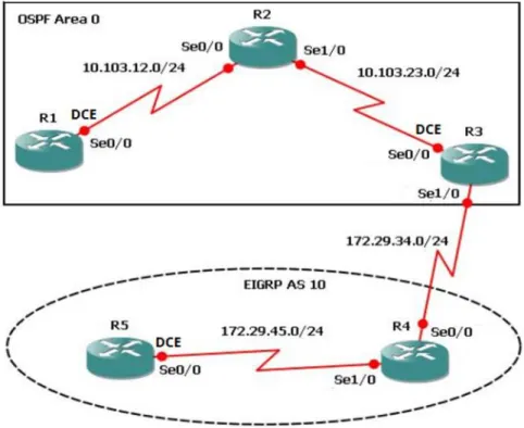
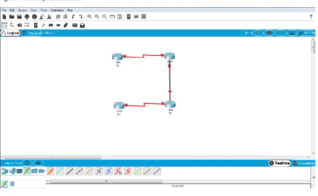
Figura 1. Escenario 1 --- 14
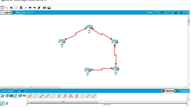
Figura 2. Montaje Escenario 1 --- 15
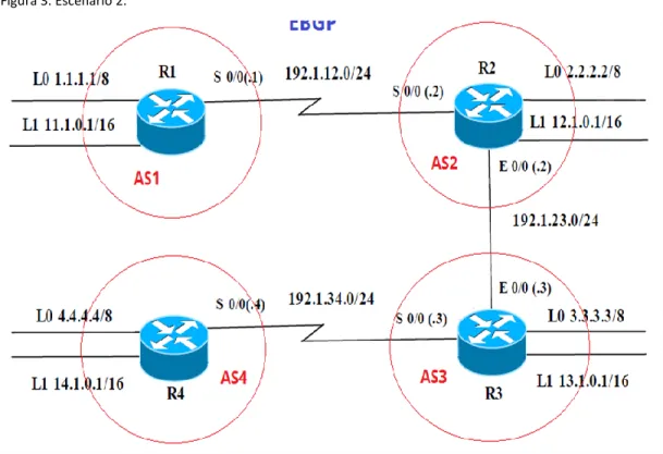
Figura 3. Escenario 2. --- 25
Figura 4. Montaje escenario 2. --- 26
Figura 5. Comprobación función de conexión establecida. --- 37
Figura 6. Escenario 3. --- 39
9 GLOSARIO
COMANDOS: es una instrucción u orden que el usuario proporciona a un sistema informático, desde la línea de comandos (como una shell) o desde una llamada de programación. Puede ser interno (contenido en el propio intérprete) o externo (contenido en un archivo ejecutable).( James. Ross, Keith (2008).)
CONFIGURAR: es un conjunto de datos que determina el valor de algunas variables de un programa o de un sistema operativo.( El Diccionario de la Real Academia Española)
ROUTER: también conocido como enrutador o rúter. Se trata de un producto de hardware que permite interconectar computadoras que funcionan en el marco de una red. (Kurose, James. Ross, Keith (2008). Computer networking. Pearson. ISBN 987-0-321-51325-0.)
RED: conjunto de equipos informáticos y software conectados entre sí.( El Diccionario de la Real Academia Española)
INTERFAZ: es el puerto (circuito físico) a través del que se envían o reciben señales desde un sistema o subsistemas hacia otros. No existe una interfaz universal, sino que existen diferentes estándares (Interfaz USB, interfaz SCSI, etc.).( DAC, Universidad Rey Juan Carlos. «Buses del sistema.»
10 RESUMEN
11 ABSTRACT
12
INTRODUCCION
En esta actividad recopilaremos los distintos talleres de aprendizajes y habilidades prácticas de CCNP en las diferentes plataformas como son CISCO y UNAD, los cuales ofrecen una muy buena estrategia para el favorecimiento del desarrollo de nuestras competencias como estudiantes. Todas estas tareas, cumplen un orden lógico de enseñanza de manera teórico-práctica, mediante unas guías y un muy buen simulador, como lo es el Packet-Tracer,
Cisco Packet Tracer que es un software de Cisco para simulación de redes de gran alcance que permite a diseñar redes, simular dispositivos, configurarlos, probar comandos de red, experimentar con diseños de red y el comportamiento como si fuera real. Cisco Packet Tracer ofrece simulación, visualización, creación, evaluación de una red aplicando conceptos tecnológicos complejos como programación de routers. Podemos crear redes virtuales con un número casi ilimitado de dispositivos, para testear y descubrir posibles problemas y solucionarlos.
Cisco utiliza este software para que los estudiantes de certificación CCNP puedan crear, configurar, explorar y solucionar problemas de redes con equipos virtuales y simular conexiones simples o complejas organizando así, nuestros conocimientos sin importar si hayan sido viejos o nuevos, lo importante es el pulimiento esencial que dan a ellos para lanzarnos como excelentes profesionales UNADISTAS en el campo de Electrónica y las Telecomunicaciones. Las redes continúan creciendo, volviéndose más complejas a medida que soportan más protocolos y más usuarios.
13
La tecnología de red LAN con nodos permite organizar los sistemas de una red local en redes VLAN. Para poder dividir una red de área local en redes VLAN, debe tener nodos compatibles con la tecnología VLAN puede configurar todos los puertos de un nodo para que transfieran datos para una única VLAN o para varias VLAN, según el diseño de configuración VLAN.
Cada fabricante utiliza procedimientos diferentes para configurar los puertos de un nodo. Las VLAN (redes de área local virtuales) pueden considerarse como dominios de difusión lógica. Una VLAN divide los grupos de usuarios de la red de una red física real en segmentos de redes lógicas. Esta implementación proporciona soporte al estándar de identificación IEEE 802.1Q VLAN con la posibilidad de permitir que en los adaptadores Ethernet se ejecuten varios ID de VLAN. Cada ID de VLAN está asociado a las capas superiores (IP, etc.) con una interfaz de Ethernet independiente y crea instancias lógicas del adaptador Ethernet para cada VLAN, por ejemplo, ent1, ent2 y así sucesivamente.
14
DESARROLLO DE LAS ACTIVIDADES
Descripción de escenarios propuestos para la prueba de habilidades. 1. ESCENARIO 1.
1.1. Aplique las configuraciones iniciales y los protocolos de enrutamiento para los routers R1, R2, R3, R4 y R5 según el diagrama. No asigne passwords en los routers. Configurar las interfaces con las direcciones que se muestran en la topología de red.
15 Se configura R1.
Router>enable
Router#configure terminal
Enter configuration commands, one per line. End with CNTL/Z. Router(config)#no ip domain-lookup
Router(config)#line con 0
Router(config-line)#logging synchronous Router(config-line)#exec-timeout 0 0 Router(config-line)#exit
Router(config)#hostname R1 R1(config)#exit
R1#
%SYS-5-CONFIG_I: Configured from console by console
R1#configure terminal
Enter configuration commands, one per line. End with CNTL/Z. R1(config)#int s 0/0/0
R1(config-if)#ip address 10.103.12.1 255.255.255.0 R1(config-if)#clock rate 64000
R1(config-if)#no shutdown
%LINK-5-CHANGED: Interface Serial0/0/0, changed state to down R1(config-if)#exit
16 R1(config)#exit
R1#
%SYS-5-CONFIG_I: Configured from console by console
R1#
Luego se configura R2. R2#enable
R2#configure terminal
Enter configuration commands, one per line. End with CNTL/Z. R2(config)#int s 0/0/0
R2(config-if)#ip address 10.103.12.2 255.255.255.0 R2(config-if)#no shutdown
R2(config-if)#exit R2(config)#exit R2#
%SYS-5-CONFIG_I: Configured from console by console
R2#configure terminal
Enter configuration commands, one per line. End with CNTL/Z. R2(config)#int s 0/1/0
R2(config-if)#ip address 10.103.23.1 255.255.255.0 R2(config-if)#clock rate 64000
R2(config-if)#no shutdown R2(config-if)#exit
R2(config)#end R2#
%SYS-5-CONFIG_I: Configured from console by console
R2#
Luego se continua con R3. Router>enable
Router#configure terminal
Enter configuration commands, one per line. End with CNTL/Z. Router(config)#no ip domain-lookup
Router(config)#line con 0
17 Router(config-line)#exec-timeout 0 0
Router(config-line)#hostname R3 R3(config)#exit
R3#
%SYS-5-CONFIG_I: Configured from console by console
R3#configure terminal
Enter configuration commands, one per line. End with CNTL/Z. R3(config)#int s 0/0/0
R3(config-if)#ip address 10.103.23.2 255.255.255.0 R3(config-if)#no shutdown
R3(config-if)#
%LINK-5-CHANGED: Interface Serial0/0/0, changed state to up
R3(config-if)#
%LINEPROTO-5-UPDOWN: Line protocol on Interface Serial0/0/0, changed state to up
R3(config-if)#exit R3(config)#int s 0/1/0
R3(config-if)#ip address 172.29.34.1 255.255.255.0 R3(config-if)#clock rate 64000
R3(config-if)#no shutdown
%LINK-5-CHANGED: Interface Serial0/1/0, changed state to down R3(config-if)#exit
R3(config)#end R3#
%SYS-5-CONFIG_I: Configured from console by console
R3#
Luego se procede a configurar R4. Router>enable
Router#configure terminal
Enter configuration commands, one per line. End with CNTL/Z. Router(config)#no ip domain-lookup
Router(config)#line con 0
18 ^
% Invalid input detected at '^' marker. Router(config-line)#exec-timeout 0 0 Router(config-line)#exit
Router(config)#hostname R4 R4(config)#int s 0/0/0
R4(config-if)#ip address 172.29.34.2 255.255.255.0 R4(config-if)#no shutdown
R4(config-if)#
%LINK-5-CHANGED: Interface Serial0/0/0, changed state to up
R4(config-if)#
%LINEPROTO-5-UPDOWN: Line protocol on Interface Serial0/0/0, changed state to up
R4(config-if)#exit R4(config)#int s 0/1/0
R4(config-if)#ip address 172.29.45.1 255.255.255.0 R4(config-if)#clock rate 64000
R4(config-if)#no shutdown
%LINK-5-CHANGED: Interface Serial0/1/0, changed state to down R4(config-if)#exit
R4(config)#end R4#
%SYS-5-CONFIG_I: Configured from console by console
R4#
Y por último se configura R5. Router>enable
Router#configure terminal
Enter configuration commands, one per line. End with CNTL/Z. Router(config)#no ip domain-lookup
Router(config)#line con 0
Router(config-line)#logging synchronous Router(config-line)#exec-timeout 0 0 Router(config-line)#exit
19 R5#
%SYS-5-CONFIG_I: Configured from console by console
R5#configure terminal
Enter configuration commands, one per line. End with CNTL/Z. R5(config)#int s 0/0/0
R5(config-if)#ip address 172.29.45.2 255.255.255.0 R5(config-if)#no shutdown
R5(config-if)#
%LINK-5-CHANGED: Interface Serial0/0/0, changed state to up
R5(config-if)#
%LINEPROTO-5-UPDOWN: Line protocol on Interface Serial0/0/0, changed state to up
R5(config-if)#exit R5(config)#exit R5#
%SYS-5-CONFIG_I: Configured from console by console
R5#
1.2. Cree cuatro nuevas interfaces de Loopback en R1 utilizando la asignación de direcciones 10.1.0.0/22 y configure esas interfaces para participar en el área 0 de OSPF.
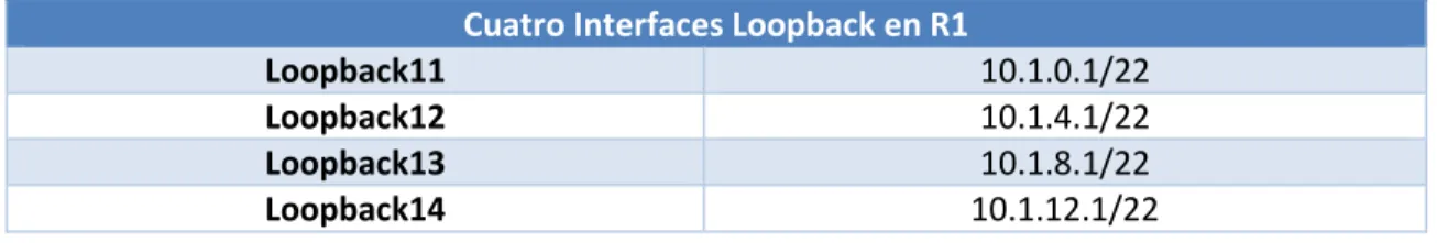
Tabla 1 Interfaces de Loopback para crear en R1.
Cuatro Interfaces Loopback en R1
Loopback11 10.1.0.1/22
Loopback12 10.1.4.1/22
Loopback13 10.1.8.1/22
Loopback14 10.1.12.1/22
Rpta:/ Se aplica la configuración en R1 R1#configure terminal
Enter configuration commands, one per line. End with CNTL/Z. R1(config)#int lo1
R1(config-if)#
20
%LINEPROTO-5-UPDOWN: Line protocol on Interface Loopback1, changed state to up
R1(config-if)#ip address 10.1.0.1 255.255.252.0 R1(config-if)#exit
R1(config)#int lo2
R1(config-if)#
%LINK-5-CHANGED: Interface Loopback2, changed state to up
%LINEPROTO-5-UPDOWN: Line protocol on Interface Loopback2, changed state to up
R1(config-if)#ip address 10.1.0.2 255.255.252.0 % 10.1.0.0 overlaps with Loopback1
R1(config-if)#exit R1(config)#int lo3
R1(config-if)#
%LINK-5-CHANGED: Interface Loopback3, changed state to up
%LINEPROTO-5-UPDOWN: Line protocol on Interface Loopback3, changed state to up
R1(config-if)#ip address 10.1.0.3 255.255.252.0 % 10.1.0.0 overlaps with Loopback1
R1(config-if)#exit R1(config)#int lo4
R1(config-if)#
%LINK-5-CHANGED: Interface Loopback4, changed state to up
%LINEPROTO-5-UPDOWN: Line protocol on Interface Loopback4, changed state to up
R1(config-if)#ip address 10.1.0.4 255.255.252.0 % 10.1.0.0 overlaps with Loopback1
R1(config-if)#exit R1(config)#end R1#
%SYS-5-CONFIG_I: Configured from console by console
21
1.3. Cree cuatro nuevas interfaces de Loopback en R5 utilizando la asignación de direcciones 172.5.0.0/22 y configure esas interfaces para participar en el Sistema Autónomo EIGRP 10.
Tabla 2. Interfaces de Loopback para crear en R5
Cuatro Interfaces Loopback en R5
Loopback51 172.5.0.1
Loopback52 172.5.4.1
Loopback53 172.5.8.1
Loopback54 172.5.12.1
Rpta:/ Se aplica la configuración en R5. R5#configure terminal
Enter configuration commands, one per line. End with CNTL/Z. R5(config)#int lo1
R5(config-if)#
%LINK-5-CHANGED: Interface Loopback1, changed state to up
%LINEPROTO-5-UPDOWN: Line protocol on Interface Loopback1, changed state to up
R5(config-if)#ip address 172.5.0.1 255.255.252.0 R5(config-if)#exit
R5(config)#int lo2
R5(config-if)#
%LINK-5-CHANGED: Interface Loopback2, changed state to up
%LINEPROTO-5-UPDOWN: Line protocol on Interface Loopback2, changed state to up
R5(config-if)#ip address 172.5.0.2 255.255.0 ^
% Invalid input detected at '^' marker.
R5(config-if)#ip address 172.5.0.2 255.255.252.0 % 172.5.0.0 overlaps with Loopback1
R5(config-if)#exit R5(config)#int lo3
R5(config-if)#
22
%LINEPROTO-5-UPDOWN: Line protocol on Interface Loopback3, changed state to up
R5(config-if)#ip address 172.5.0.3 255.255.252.0 % 172.5.0.0 overlaps with Loopback1
R5(config-if)#exit R5(config)#int lo4
R5(config-if)#
%LINK-5-CHANGED: Interface Loopback4, changed state to up
%LINEPROTO-5-UPDOWN: Line protocol on Interface Loopback4, changed state to up
R5(config-if)#ip address 172.5.0.4 255.255.252.0 % 172.5.0.0 overlaps with Loopback1
R5(config-if)#exit
R5(config)#router eigrp 10
R5(config-router)#no auto-summary
R5(config-router)#network 172.5.0.0 0.0.3.255 R5(config-router)#exit
R5(config)#end R5#
%SYS-5-CONFIG_I: Configured from console by console
R5#
1.4. Analice la tabla de enrutamiento de R3 y verifique que R3 está aprendiendo las nuevas interfaces de Loopback mediante el comando show ip route.
Rpta:/ Se aplica el comando show ip route observando el código de resultado en R3 R3#show ip route
Codes: L - local, C - connected, S - static, R - RIP, M - mobile, B - BGP D - EIGRP, EX - EIGRP external, O - OSPF, IA - OSPF inter area
N1 - OSPF NSSA external type 1, N2 - OSPF NSSA external type 2 E1 - OSPF external type 1, E2 - OSPF external type 2, E - EGP i - IS-IS, L1 - IS-IS level-1, L2 - IS-IS level-2, ia - IS-IS inter area * - candidate default, U - per-user static route, o - ODR P - periodic downloaded static route
23 10.0.0.0/8 is variably subnetted, 2 subnets, 2 masks C 10.103.23.0/24 is directly connected, Serial0/0/0 L 10.103.23.2/32 is directly connected, Serial0/0/0 172.29.0.0/16 is variably subnetted, 2 subnets, 2 masks C 172.29.34.0/24 is directly connected, Serial0/1/0 L 172.29.34.1/32 is directly connected, Serial0/1/0
R3#
1.5. Configure R3 para redistribuir las rutas EIGRP en OSPF usando el costo de 50000 y luego redistribuya las rutas OSPF en EIGRP usando un ancho de banda T1 y 20,000 microsegundos de retardo.
Rpta:/ Se configura R3. R3#configure terminal
Enter configuration commands, one per line. End with CNTL/Z. R3(config)#router eigrp 10
R3(config-router)#redistribute ospf 1 metric 10000 100 255 1 1500 R3(config-router)#network 172.5.0.0 0.0.3.255
R3(config-router)#auto-summary R3(config-router)#exit
R3(config)#router ospf 1
R3(config-router)#log-adjacency-changes R3(config-router)#redistribute eigrp 10 subnets R3(config-router)#network 10.1.0.0 0.0.3.255 area 0 R3(config-router)#exit
R3(config)#exit R3#
%SYS-5-CONFIG_I: Configured from console by console
R3#
1.6. Verifique en R1 y R5 que las rutas del sistema autónomo opuesto existen en su tabla de enrutamiento mediante el comando show ip route.
Rpta:/ Se aplica comando show ip route para análisis de tabla de enrutamiento en R1
R1#show ip route
24
D - EIGRP, EX - EIGRP external, O - OSPF, IA - OSPF inter area N1 - OSPF NSSA external type 1, N2 - OSPF NSSA external type 2 E1 - OSPF external type 1, E2 - OSPF external type 2, E - EGP i - IS-IS, L1 - IS-IS level-1, L2 - IS-IS level-2, ia - IS-IS inter area * - candidate default, U - per-user static route, o - ODR P - periodic downloaded static route
Gateway of last resort is not set
10.0.0.0/8 is variably subnetted, 4 subnets, 3 masks C 10.1.0.0/22 is directly connected, Loopback1 L 10.1.0.1/32 is directly connected, Loopback1 C 10.103.12.0/24 is directly connected, Serial0/0/0 L 10.103.12.1/32 is directly connected, Serial0/0/0
R1#
Y luego se procede el procedimiento para R5 R5#show ip route
Codes: L - local, C - connected, S - static, R - RIP, M - mobile, B - BGP D - EIGRP, EX - EIGRP external, O - OSPF, IA - OSPF inter area
N1 - OSPF NSSA external type 1, N2 - OSPF NSSA external type 2 E1 - OSPF external type 1, E2 - OSPF external type 2, E - EGP i - IS-IS, L1 - IS-IS level-1, L2 - IS-IS level-2, ia - IS-IS inter area * - candidate default, U - per-user static route, o - ODR P - periodic downloaded static route
Gateway of last resort is not set
172.5.0.0/16 is variably subnetted, 2 subnets, 2 masks C 172.5.0.0/22 is directly connected, Loopback1 L 172.5.0.1/32 is directly connected, Loopback1
172.29.0.0/16 is variably subnetted, 2 subnets, 2 masks C 172.29.45.0/24 is directly connected, Serial0/0/0 L 172.29.45.2/32 is directly connected, Serial0/0/0
25 2. ESCENARIO 2.
2.1. Información para configuración de los Routers. Tabla 3. Información para configuración del Router R1.
Interfaz Dirección IP Máscara
Loopback 0 1.1.1.1 255.0.0.0
Loopback 1 11.1.0.1 255.255.0.0
S 0/0 192.1.12.1 255.255.255.0
Tabla 4. Información para configuración del Router R2.
Interfaz Dirección IP Máscara
Loopback 0 2.2.2.2 255.0.0.0
Loopback 1 12.1.0.1 255.255.0.0
g 0/0 192.1.12.2 255.255.255.0
G 0/0 192.1.23.2 255.255.255.0
26 Tabla 5. Información para configuración del Router R3.
Tabla 6. Información para configuración del Router R4.
Interfaz Dirección IP Máscara
Loopback 0 4.4.4.4 255.0.0.0
Loopback 1 14.1.0.1 255.255.0.0
S 0/0 192.1.34.4 255.255.255.0
2.2. Configure una relación de vecino BGP entre R1 y R2. R1 debe estar en AS1 y R2 debe estar en AS2. Anuncie las direcciones de Loopback en BGP. Codifique los ID para los routers BGP como 11.11.11.11 para R1 y como 22.22.22.22 para R2. Presente el paso a con los comandos utilizados y la salida del comando show ip route.
Rpta:/ Se toma evidencia del montaje del escenario 2.
Interfaz Dirección IP Máscara
Loopback 0 3.3.3.3 255.0.0.0
Loopback 1 13.1.0.1 255.255.0.0
g 0/0 192.1.23.3 255.255.255.0
g 0/0 192.1.34.3 255.255.255.0
27 Se inicia la configuración con R1
Router>enable
Router#configure terminal
Enter configuration commands, one per line. End with CNTL/Z. Router(config)#no ip domain-lookup
Router(config)#line con 0
Router(config-line)#logging synchronous Router(config-line)#exec-timeout 0 0 Router(config-line)#exit
Router(config)#hostname R1 R1(config)#exit
R1#
%SYS-5-CONFIG_I: Configured from console by console
R1#
R1#configure terminal
Enter configuration commands, one per line. End with CNTL/Z. R1(config)#int s 0/0/0
R1(config-if)#ip address 192.1.12.1 255.255.255.0 R1(config-if)#clock rate 64000
R1(config-if)#no shutdown
%LINK-5-CHANGED: Interface Serial0/0/0, changed state to down R1(config-if)#exit
R1(config)#int lo0
R1(config-if)#
%LINK-5-CHANGED: Interface Loopback0, changed state to up
%LINEPROTO-5-UPDOWN: Line protocol on Interface Loopback0, changed state to up
R1(config-if)#ip address 1.1.1.1 255.0.0.0 R1(config-if)#exit
R1(config)#int lo1
R1(config-if)#
%LINK-5-CHANGED: Interface Loopback1, changed state to up
%LINEPROTO-5-UPDOWN: Line protocol on Interface Loopback1, changed state to up
28 R1(config-if)#exit
R1(config)# R1#
%SYS-5-CONFIG_I: Configured from console by console
R1#
Se continua la configuración con R2. Router>enable
Router#configure terminal
Enter configuration commands, one per line. End with CNTL/Z. Router(config)#no ip domain-lookup
Router(config)#line con 0
Router(config-line)#logging synchronous Router(config-line)#exec-timeout 0 0 Router(config-line)#exit
Router(config)#hostname R2 R2(config)#exit
R2#
%SYS-5-CONFIG_I: Configured from console by console
R2#
R2#configure terminal
Enter configuration commands, one per line. End with CNTL/Z. R2(config)#ip address 2.2.2.2 255.0.0.0
^
% Invalid input detected at '^' marker. R2(config)#int lo0
R2(config-if)#
%LINK-5-CHANGED: Interface Loopback0, changed state to up
%LINEPROTO-5-UPDOWN: Line protocol on Interface Loopback0, changed state to up
R2(config-if)#ip address 2.2.2.2 255.0.0.0 R2(config-if)#exit
R2(config)#int lo1
R2(config-if)#
29
%LINEPROTO-5-UPDOWN: Line protocol on Interface Loopback1, changed state to up
R2(config-if)#ip address 12.1.0.1 255.255.0.0 R2(config-if)#exit
R2(config)#int s 0/0/0
R2(config-if)#ip address 192.1.12.2 255.255.255.0 R2(config-if)#no shutdown
R2(config-if)#
%LINK-5-CHANGED: Interface Serial0/0/0, changed state to up
R2(config-if)#
%LINEPROTO-5-UPDOWN: Line protocol on Interface Serial0/0/0, changed state to up
R2(config-if)#exit R2(config)#int g0/0
R2(config-if)#ip address 192.1.23.2 255.255.255.0 R2(config-if)#exit
R2(config)#exit R2#
%SYS-5-CONFIG_I: Configured from console by console
R2#
Se continua la configuración con R3. Router>enable
Router#configure terminal
Enter configuration commands, one per line. End with CNTL/Z. Router(config)#no ip domain-lookup
Router(config)#line con 0
Router(config-line)#logging synchronous Router(config-line)#exec-timeout 0 0 Router(config-line)#exit
Router(config)#hostname R3 R3(config)#exit
R3#
%SYS-5-CONFIG_I: Configured from console by console
30 R3#configure terminal
Enter configuration commands, one per line. End with CNTL/Z. R3(config)#int lo0
R3(config-if)#
%LINK-5-CHANGED: Interface Loopback0, changed state to up
%LINEPROTO-5-UPDOWN: Line protocol on Interface Loopback0, changed state to up
R3(config-if)#ip address 3.3.3.3 255.0.0.0 R3(config-if)#exit
R3(config)#int lo1
R3(config-if)#
%LINK-5-CHANGED: Interface Loopback1, changed state to up
%LINEPROTO-5-UPDOWN: Line protocol on Interface Loopback1, changed state to up
R3(config-if)#ip address 13.1.0.1 255.255.0.0 R3(config-if)#exit
R3(config)#int g0/0
R3(config-if)#ip address 192.1.23.3 255.255.255.0 R3(config-if)#exit
R3(config)#int s0/0/0
R3(config-if)#ip address 192.1.34.3 255.255.255.0 R3(config-if)#no shutdown
%LINK-5-CHANGED: Interface Serial0/0/0, changed state to down R3(config-if)#exit
R3(config)#exit R3#
%SYS-5-CONFIG_I: Configured from console by console
R3#
Se continua la configuración con R4. Router>enable
Router#configure terminal
31 Router(config)#line con 0
Router(config-line)#logging synchronous Router(config-line)#exec-timeout 0 0 Router(config-line)#exit
Router(config)#hostname R4 R4(config)#exit
R4#
%SYS-5-CONFIG_I: Configured from console by console
R4#
R4#configure terminal
Enter configuration commands, one per line. End with CNTL/Z. R4(config)#int lo0
R4(config-if)#
%LINK-5-CHANGED: Interface Loopback0, changed state to up
%LINEPROTO-5-UPDOWN: Line protocol on Interface Loopback0, changed state to up
R4(config-if)#ip address 4.4.4.4 255.0.0.0 R4(config-if)#exit
R4(config)#int lo1
R4(config-if)#
%LINK-5-CHANGED: Interface Loopback1, changed state to up
%LINEPROTO-5-UPDOWN: Line protocol on Interface Loopback1, changed state to up
R4(config-if)#ip address 14.1.0.1 255.255.0.0 R4(config-if)#exit
R4(config)#int s0/0/0
R4(config-if)#ip address 192.1.34.4 255.255.255.0 R4(config-if)#no shutdown
R4(config-if)#
%LINK-5-CHANGED: Interface Serial0/0/0, changed state to up
R4(config-if)#exit R4(config)#exit R4#
32 R4#
Se configura vecino BGP para R1 y R2 en R1. R1#configure terminal
Enter configuration commands, one per line. End with CNTL/Z. R1(config)#router bgp 100
R1(config-router)#
R1(config-router)#network 192.1.12.1 mask 255.255.255.0 R1(config-router)#neighbor 192.1.12.2 remote-as 200 R1(config-router)#exit
R1(config)#exit R1#
%SYS-5-CONFIG_I: Configured from console by console
R1#
Se configura vecino BGP para R1 y R2 en R2. R2#configure terminal
Enter configuration commands, one per line. End with CNTL/Z. R2(config)#router bgp 200
R2(config-router)#network 192.1.12.2 mask 255.255.255.0 R2(config-router)#neighbor 192.1.12.1 remote-as 100
R2(config-router)#%BGP-5-ADJCHANGE: neighbor 192.1.12.1 Up
R2(config-router)#exit R2(config)#exit
R2#
%SYS-5-CONFIG_I: Configured from console by console
R2#
Se establece la función BGP. R1#ping 192.1.12.2
Type escape sequence to abort.
33
Success rate is 100 percent (5/5), round-trip min/avg/max = 1/1/2 ms
R2#ping 192.1.12.1
Type escape sequence to abort.
Sending 5, 100-byte ICMP Echos to 192.1.12.1, timeout is 2 seconds: !!!!!
Success rate is 100 percent (5/5), round-trip min/avg/max = 1/3/12 ms
R2#
Se codifican los ID para los routers BGP. R1#configure terminal
Enter configuration commands, one per line. End with CNTL/Z. R1(config)#router bgp 100
R1(config-router)#bgp router-id 11.11.11.11
R1(config-router)#%BGP-5-ADJCHANGE: neighbor 192.1.12.2 Up
R1(config-router)#exit R1(config)#exit
R1#
%SYS-5-CONFIG_I: Configured from console by console
R1#
R2#configure terminal
Enter configuration commands, one per line. End with CNTL/Z. R2(config)#router bgp 200
R2(config-router)#bgp router-id 22.22.22.22
R2(config-router)#%BGP-5-ADJCHANGE: neighbor 192.1.12.1 Up
R2(config-router)#exit R2(config)#exit
R2#
%SYS-5-CONFIG_I: Configured from console by console
R2#
R1#show ip route
34
N1 - OSPF NSSA external type 1, N2 - OSPF NSSA external type 2 E1 - OSPF external type 1, E2 - OSPF external type 2, E - EGP i - IS-IS, L1 - IS-IS level-1, L2 - IS-IS level-2, ia - IS-IS inter area * - candidate default, U - per-user static route, o - ODR P - periodic downloaded static route
Gateway of last resort is not set
1.0.0.0/8 is variably subnetted, 2 subnets, 2 masks C 1.0.0.0/8 is directly connected, Loopback0 L 1.1.1.1/32 is directly connected, Loopback0 11.0.0.0/8 is variably subnetted, 2 subnets, 2 masks C 11.1.0.0/16 is directly connected, Loopback1 L 11.1.0.1/32 is directly connected, Loopback1
192.1.12.0/24 is variably subnetted, 2 subnets, 2 masks C 192.1.12.0/24 is directly connected, Serial0/0/0 L 192.1.12.1/32 is directly connected, Serial0/0/0
R1#
2.3. Configure una relación de vecino BGP entre R2 y R3. R2 ya debería estar configurado en AS2 y R3 debería estar en AS3. Anuncie las direcciones de Loopback de R3 en BGP. Codifique el ID del router R3 como 33.33.33.33. Presente el paso a con los comandos utilizados y la salida del comando show ip route. Rpta:/ Se inicia con R2.
R2#configure terminal
Enter configuration commands, one per line. End with CNTL/Z. R2(config)#router bgp 200
R2(config-router)#network 192.1.12.2 mask 255.255.255.0 R2(config-router)#neighbor 192.1.12.3 remote-as 300 R2(config-router)#exit
R2(config)#exit R2#
%SYS-5-CONFIG_I: Configured from console by console
R2#
35 R3#configure terminal
Enter configuration commands, one per line. End with CNTL/Z. R3(config)#router bgp 300
R3(config-router)#network 192.1.12.3 mask 255.255.255.0 R3(config-router)#neigbor 192.1.12.2 remote-as 200 ^
% Invalid input detected at '^' marker.
R3(config-router)#neighbor 192.1.12.2 remote-as 200 R3(config-router)#exit
R3(config)#exit R3#
%SYS-5-CONFIG_I: Configured from console by console
R3#
Se procede a codificar el ID para el router R3. R3#configure terminal
Enter configuration commands, one per line. End with CNTL/Z. R3(config)#router bgp 300
R3(config-router)#bgp router-id 33.33.33.33 R3(config-router)#exit
R3(config)#end R3#
%SYS-5-CONFIG_I: Configured from console by console
R3#show ip bgp
BGP table version is 1, local router ID is 33.33.33.33
Status codes: s suppressed, d damped, h history, * valid, > best, i - internal, r RIB-failure, S Stale
Origin codes: i - IGP, e - EGP, ? - incomplete
Network Next Hop Metric LocPrf Weight Path
R3#
36
Loopback 0 en BGP. Anuncie la red Loopback de R4 en BGP. Presente el paso a con los comandos utilizados y la salida del comando show ip route.
Rpta:/ Se inicia con R3. R3#configure terminal
Enter configuration commands, one per line. End with CNTL/Z. R3(config)#router bgp 300
R3(config-router)#network 3.3.3.3 mask 255.0.0.0 R3(config-router)#neighbor 4.4.4.4 remote-as 400 R3(config-router)#exit
R3(config)#exit R3#
%SYS-5-CONFIG_I: Configured from console by console
R3#
Luego se continua con R4. R4#configure terminal
Enter configuration commands, one per line. End with CNTL/Z. R4(config)#router bgp 400
R4(config-router)#network 4.4.4.4 mask 255.0.0.0 R4(config-router)#neighbor 3.3.3.3 remote-as 300 R4(config-router)#exit
R4(config)#exit R4#
%SYS-5-CONFIG_I: Configured from console by console R4#
Se procede a codificar el ID para el router R4. R4#configure terminal
Enter configuration commands, one per line. End with CNTL/Z. R4(config)#router bgp 400
R4(config-router)#bgp router-id 44.44.44.44 R4(config-router)#exit
R4(config)#exit R4#
%SYS-5-CONFIG_I: Configured from console by console
37 R4#show ip bgp
BGP table version is 2, local router ID is 44.44.44.44
Status codes: s suppressed, d damped, h history, * valid, > best, i - internal, r RIB-failure, S Stale
Origin codes: i - IGP, e - EGP, ? - incomplete
Network Next Hop Metric LocPrf Weight Path *> 4.0.0.0/8 0.0.0.0 0 0 32768 i
R4#
Se crear ruta estática y se toma captura de pantalla que comprueba la función de conexión establecida.
R3#ping 192.1.34.4
Type escape sequence to abort.
Sending 5, 100-byte ICMP Echos to 192.1.34.4, timeout is 2 seconds: !!!!!
Success rate is 100 percent (5/5), round-trip min/avg/max = 1/3/15 ms
R3#
R4#ping 192.1.34.3
Type escape sequence to abort.
Sending 5, 100-byte ICMP Echos to 192.1.34.3, timeout is 2 seconds: !!!!!
38
Success rate is 100 percent (5/5), round-trip min/avg/max = 1/2/10 ms
R4#show ip route
Codes: L - local, C - connected, S - static, R - RIP, M - mobile, B - BGP D - EIGRP, EX - EIGRP external, O - OSPF, IA - OSPF inter area
N1 - OSPF NSSA external type 1, N2 - OSPF NSSA external type 2 E1 - OSPF external type 1, E2 - OSPF external type 2, E - EGP i - IS-IS, L1 - IS-IS level-1, L2 - IS-IS level-2, ia - IS-IS inter area * - candidate default, U - per-user static route, o - ODR P - periodic downloaded static route
Gateway of last resort is not set
4.0.0.0/8 is variably subnetted, 2 subnets, 2 masks C 4.0.0.0/8 is directly connected, Loopback0 L 4.4.4.4/32 is directly connected, Loopback0 14.0.0.0/8 is variably subnetted, 2 subnets, 2 masks C 14.1.0.0/16 is directly connected, Loopback1 L 14.1.0.1/32 is directly connected, Loopback1
192.1.34.0/24 is variably subnetted, 2 subnets, 2 masks C 192.1.34.0/24 is directly connected, Serial0/0/0 L 192.1.34.4/32 is directly connected, Serial0/0/0
39 3. ESCENARIO 3.
3.1. Configurar VTP.
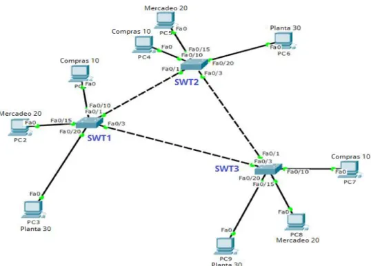
3.1.1. Todos los switches se configurarán para usar VTP para las actualizaciones de VLAN. El switch SWT2 se configurará como el servidor. Los switches SWT1 y SWT3 se configurarán como clientes. Los switches estarán en el dominio VPT llamado CCNP y usando la contraseña cisco.
Rpta:/ Se monta el Escenario 3. Figura 6. Escenario 3.
40 Se aplica la configuración en SW1.
Switch>enable
Switch#configure terminal
Enter configuration commands, one per line. End with CNTL/Z. Switch(config)#no ip domain-lookup
Switch(config)#line con 0
Switch(config-line)#logging synchronous Switch(config-line)#exec-timeout 0 0 Switch(config-line)#exit
Switch(config)#hostname Sw1 Sw1(config)#VTP domain CCNP
Changing VTP domain name from NULL to CCNP Sw1(config)#vtp mode client
Setting device to VTP CLIENT mode. Sw1(config)#vtp password cisco
Setting device VLAN database password to cisco Sw1(config)#exit
Sw1#
%SYS-5-CONFIG_I: Configured from console by console
Sw1#
41 Switch>enable
Switch#configure terminal
Enter configuration commands, one per line. End with CNTL/Z. Switch(config)#no ip domain-lookup
Switch(config)#line con 0
Switch(config-line)#logging synchronous Switch(config-line)#exec-timeout 0 0 Switch(config-line)#exit
Switch(config)#hostname Sw2 Sw2(config)#exit
Sw2#
%SYS-5-CONFIG_I: Configured from console by console
Sw2#configure terminal
Enter configuration commands, one per line. End with CNTL/Z. Sw2(config)#vtp mode server
Device mode already VTP SERVER. Sw2(config)#vtp domain CCNP
Changing VTP domain name from NULL to CCNP Sw2(config)#vtp password cisco
Setting device VLAN database password to cisco Sw2(config)#exit
Sw2#
%SYS-5-CONFIG_I: Configured from console by console
Sw2#
Se aplica la configuración en SW3. Switch>enable
Switch#configure terminal
Enter configuration commands, one per line. End with CNTL/Z. Switch(config)#no ip domain-lookup
Switch(config)#line con 0
Switch(config-line)#logging synchronous Switch(config-line)#exec-timeout 0 0 Switch(config-line)#exit
Switch(config)#hostname Sw3 Sw3(config)#exit
42
%SYS-5-CONFIG_I: Configured from console by console
Sw3#configure terminal
Enter configuration commands, one per line. End with CNTL/Z. Sw3(config)#VTP domain CCNP
Changing VTP domain name from NULL to CCNP Sw3(config)#vtp mode client
Setting device to VTP CLIENT mode. Sw3(config)#vtp password cisco
Setting device VLAN database password to cisco Sw3(config)#exit
Sw3#
%SYS-5-CONFIG_I: Configured from console by console
Sw3#
3.1.2. Verifique las configuraciones mediante el comando show vtp status. Rpta:/ Se verifica la configuración mediante el comando show vtp status en SW1 Sw1#show vtp status
VTP Version : 2
Configuration Revision : 0
Maximum VLANs supported locally : 255 Number of existing VLANs : 5
VTP Operating Mode : Client VTP Domain Name : CCNP VTP Pruning Mode : Disabled VTP V2 Mode : Disabled
VTP Traps Generation : Disabled
MD5 digest : 0xDA 0xBF 0x42 0x0D 0x90 0xBC 0xBE 0x41 Configuration last modified by 0.0.0.0 at 0-0-00 00:00:00 Sw1#
Luego se procede a aplicar el comando de verificación show vtp status en SW2. Sw2#show vtp status
VTP Version : 2
Configuration Revision : 0
43 VTP Operating Mode : Server
VTP Domain Name : CCNP VTP Pruning Mode : Disabled VTP V2 Mode : Disabled
VTP Traps Generation : Disabled
MD5 digest : 0xDA 0xBF 0x42 0x0D 0x90 0xBC 0xBE 0x41 Configuration last modified by 0.0.0.0 at 0-0-00 00:00:00 Local updater ID is 0.0.0.0 (no valid interface found) Sw2#
Y por último se procede a aplicar el comando de verificación show vtp status en SW3.
Sw3#show vtp status VTP Version : 2
Configuration Revision : 0
Maximum VLANs supported locally : 255 Number of existing VLANs : 5
VTP Operating Mode : Client VTP Domain Name : CCNP VTP Pruning Mode : Disabled VTP V2 Mode : Disabled
VTP Traps Generation : Disabled
MD5 digest : 0xDA 0xBF 0x42 0x0D 0x90 0xBC 0xBE 0x41 Configuration last modified by 0.0.0.0 at 0-0-00 00:00:00 Sw3#
3.2. Configurar DTP (Dynamic Trunking Protocol).
3.2.1. Configure un enlace troncal ("trunk") dinámico entre SWT1 y SWT2. Debido a que el modo por defecto es dynamic auto, solo un lado del enlace debe configurarse como dynamic desirable.
Rpta:/ Se configura SW1. Sw1#configure terminal
Enter configuration commands, one per line. End with CNTL/Z. Sw1(config)#int fa 0/1
Sw1(config-if)#switchport mode dynamic desirable
44
%LINEPROTO-5-UPDOWN: Line protocol on Interface FastEthernet0/1, changed state to up
%LINEPROTO-5-UPDOWN: Line protocol on Interface FastEthernet0/1, changed state to down
%LINEPROTO-5-UPDOWN: Line protocol on Interface FastEthernet0/1, changed state to up
Sw1(config-if)#exit Sw1(config)#end Sw1#
%SYS-5-CONFIG_I: Configured from console by console
Sw1#
3.2.2. Verifique el enlace "trunk" entre SWT1 y SWT2 usando el comando show interfaces trunk.
Rpta:/ Se verifica en enlace en SW1 aplicando el comando show interfaces trunk Sw1#show interfaces trunk
Port Mode Encapsulation Status Native vlan Fa0/1 desirable n-802.1q trunking 1
Port Vlans allowed on trunk Fa0/1 1-1005
Port Vlans allowed and active in management domain Fa0/1 1
Port Vlans in spanning tree forwarding state and not pruned Fa0/1 1
Sw1#
3.2.3. Entre SWT1 y SWT3 configure un enlace "trunk" estático utilizando el comando switchport mode trunk en la interfaz F0/3 de SWT1.
Rpta:/ Se configura SW1 Sw1#configure terminal
45 Sw1(config)#int fa 0/3
Sw1(config-if)#switchport mode trunk
Sw1(config-if)#
%LINEPROTO-5-UPDOWN: Line protocol on Interface FastEthernet0/3, changed state to down
%LINEPROTO-5-UPDOWN: Line protocol on Interface FastEthernet0/3, changed state to up
Sw1(config-if)#exit Sw1(config)#end Sw1#
%SYS-5-CONFIG_I: Configured from console by console
Sw1#
3.2.4. Verifique el enlace "trunk" el comando show interfaces trunk en SWT1. Rpta:/ Se verifica la configuración en SWT1 con el comando show interfaces trunk Sw1#show interfaces trunk
Port Mode Encapsulation Status Native vlan Fa0/1 desirable n-802.1q trunking 1
Fa0/3 on 802.1q trunking 1
Port Vlans allowed on trunk Fa0/1 1-1005
Fa0/3 1-1005
Port Vlans allowed and active in management domain Fa0/1 1
Fa0/3 1
Port Vlans in spanning tree forwarding state and not pruned Fa0/1 1
Fa0/3 1
Sw1#
46 Rpta:/ Se configura en SW2.
Sw2#configure terminal
Enter configuration commands, one per line. End with CNTL/Z. Sw2(config)#int fa 0/3
Sw2(config-if)#switchport mode trunk
Sw2(config-if)#
%LINEPROTO-5-UPDOWN: Line protocol on Interface FastEthernet0/3, changed state to down
%LINEPROTO-5-UPDOWN: Line protocol on Interface FastEthernet0/3, changed state to up
Sw2(config-if)#exit Sw2(config)#end Sw2#
%SYS-5-CONFIG_I: Configured from console by console
Sw2#show interfaces trunk
Port Mode Encapsulation Status Native vlan Fa0/1 auto n-802.1q trunking 1
Fa0/3 on 802.1q trunking 1
Port Vlans allowed on trunk Fa0/1 1-1005
Fa0/3 1-1005
Port Vlans allowed and active in management domain Fa0/1 1
Fa0/3 1
Port Vlans in spanning tree forwarding state and not pruned Fa0/1 none
Fa0/3 1
Sw2#
3.3. Agregar VLANs y asignar puertos.
47 Rpta:/ Se configura en SW2.
Sw2#
Sw2#configure terminal
Enter configuration commands, one per line. End with CNTL/Z. Sw2(config)#vlan 10
Sw2(config-vlan)#name VLAN_Compras Sw2(config-vlan)#exit
Sw2(config)#vlan 20
Sw2(config-vlan)#name VLAN_Mercadeo Sw2(config-vlan)#exit
Sw2(config)#vlan 30
Sw2(config-vlan)#name VLAN_Planta Sw2(config-vlan)#exit
Sw2(config)#vlan 99
Sw2(config-vlan)#name VLAN_Admon Sw2(config-vlan)#exit
Sw2(config)#end Sw2#
%SYS-5-CONFIG_I: Configured from console by console
Sw2#
Y luego se configura en SW1. Sw1#
Sw1#configure terminal
Enter configuration commands, one per line. End with CNTL/Z. Sw1(config)#int fa 0/10
Sw1(config-if)#sw access vlan 10 Sw1(config-if)#exit
Sw1(config)#end Sw1#
%SYS-5-CONFIG_I: Configured from console by console
Sw1#
48 Sw1#show vlan
VLAN Name Status Ports
---- --- --- --- 1 default active Fa0/2, Fa0/4, Fa0/5, Fa0/6
Fa0/7, Fa0/8, Fa0/9, Fa0/11 Fa0/12, Fa0/13, Fa0/14, Fa0/15 Fa0/16, Fa0/17, Fa0/18, Fa0/19 Fa0/20, Fa0/21, Fa0/22, Fa0/23 Fa0/24, Gig0/1, Gig0/2
10 VLAN_Compras active Fa0/10 20 VLAN_Mercadeo active 30 VLAN_Planta active 99 VLAN_Admon active 1002 fddi-default active 1003 token-ring-default active 1004 fddinet-default active 1005 trnet-default active
VLAN Type SAID MTU Parent RingNo BridgeNo Stp BrdgMode Trans1 Trans2 ---- --- --- --- --- --- --- ---- --- --- ---
1 enet 100001 1500 - - - 0 0 10 enet 100010 1500 - - - 0 0 20 enet 100020 1500 - - - 0 0 30 enet 100030 1500 - - - 0 0 99 enet 100099 1500 - - - 0 0 1002 fddi 101002 1500 - - - 0 0 1003 tr 101003 1500 - - - 0 0
1004 fdnet 101004 1500 - - - ieee - 0 0 1005 trnet 101005 1500 - - - ibm - 0 0
VLAN Type SAID MTU Parent RingNo BridgeNo Stp BrdgMode Trans1 Trans2 ---- --- --- --- --- --- --- ---- --- --- ---
Remote SPAN VLANs
---
Primary Secondary Type Ports
49
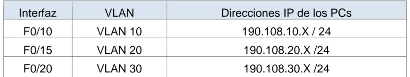
3.3.3. Asocie los puertos a las VLAN y configure las direcciones IP de acuerdo con la siguiente tabla.
Tabla 7. Puertos a las VLAN y configuración de las direcciones IP.
Interfaz VLAN Direcciones IP de los PCs
F0/10 VLAN 10 190.108.10.X / 24
F0/15 VLAN 20 190.108.20.X /24
F0/20 VLAN 30 190.108.30.X /24
X = número de cada PC particular.
3.3.4. Configure el puerto F0/10 en modo de acceso para SWT1, SWT2 y SWT3 y asígnelo a la VLAN 10.
3.3.5. Repita el procedimiento para los puertos F0/15 y F0/20 en SWT1, SWT2 y SWT3. Asigne las VLANs y las direcciones IP de los PCs de acuerdo con la tabla de arriba.
Rpta:/ Se configura SW1. Sw1#configure terminal
Enter configuration commands, one per line. End with CNTL/Z. Sw1(config)#int f 0/10
Sw1(config-if)#switchport mode access Sw1(config-if)#switchport access vlan 10 Sw1(config-if)#exit
Sw1(config)#end Sw1#
%SYS-5-CONFIG_I: Configured from console by console
Sw1#configure terminal
Enter configuration commands, one per line. End with CNTL/Z. Sw1(config)#int f 0/15
Sw1(config-if)#switchport mode access Sw1(config-if)#switchport access vlan 20 Sw1(config-if)#exit
Sw1(config)#int f 0/20
50 Sw1(config)#int f 0/20
Sw1(config-if)#switchport mode access Sw1(config-if)#switchport access vlan 30 Sw1(config-if)#exit
Sw1(config)#end Sw1#
%SYS-5-CONFIG_I: Configured from console by console
Sw1#
Se configura SW2. Sw2#configure terminal
Enter configuration commands, one per line. End with CNTL/Z. Sw2(config)#in f 0/10
Sw2(config-if)#switchport mode access Sw2(config-if)#switchport access vlan 10 Sw2(config-if)#exit
Sw2(config)#in f 0/15
Sw2(config-if)#switchport mode access Sw2(config-if)#switchport access vlan 20 Sw2(config-if)#exit
Sw2(config)#in f 0/20
Sw2(config-if)#switchport mode access Sw2(config-if)#switchport access vlan 30 Sw2(config-if)#exit
Sw2(config)#end Sw2#
%SYS-5-CONFIG_I: Configured from console by console
Sw2#
Se configura SW3. Sw3#configure terminal
Enter configuration commands, one per line. End with CNTL/Z. Sw3(config)#int f 0/10
51 Sw3(config)#int f 0/15
Sw3(config-if)#switchport mode access Sw3(config-if)#switchport access vlan 20 Sw3(config-if)#exit
Sw3(config)#int f 0/20
Sw3(config-if)#switchport mode access Sw3(config-if)#switchport access vlan 30 Sw3(config-if)#exit
Sw3(config)#end Sw3#
%SYS-5-CONFIG_I: Configured from console by console
Sw3#
3.4. Configurar las direcciones IP en los Switches.
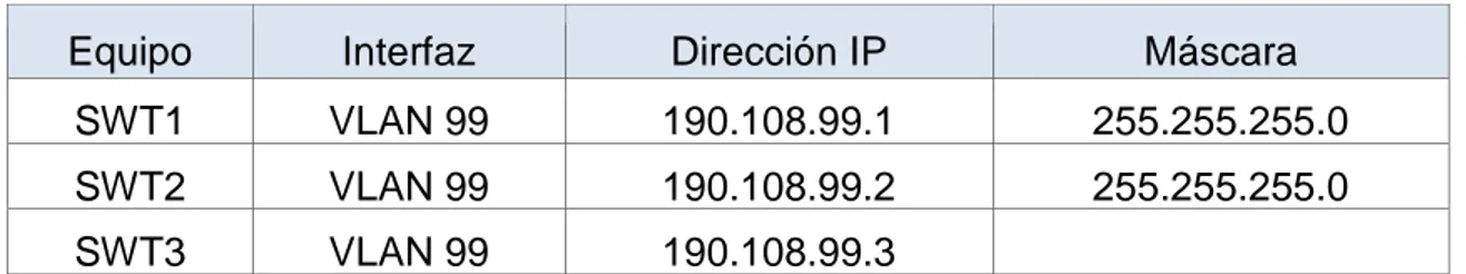
3.4.1. En cada uno de los Switches asigne una dirección IP al SVI (Switch Virtual Interface) para VLAN 99 de acuerdo con la siguiente tabla de direccionamiento y active la interfaz.
Tabla 8. Configuración de direcciones IP en los Switches.
Equipo Interfaz Dirección IP Máscara
SWT1 VLAN 99 190.108.99.1 255.255.255.0
SWT2 VLAN 99 190.108.99.2 255.255.255.0
SWT3 VLAN 99 190.108.99.3
Rpta:/ Se configura SW1 Sw1#configure terminal
Enter configuration commands, one per line. End with CNTL/Z. Sw1(config)#int vlan 99
Sw1(config-if)#
%LINK-5-CHANGED: Interface Vlan99, changed state to up
%LINEPROTO-5-UPDOWN: Line protocol on Interface Vlan99, changed state to up
Sw1(config-if)#ip address 190.108.99.1 255.255.255.0 Sw1(config-if)#no shutdown
52
%SYS-5-CONFIG_I: Configured from console by console
Sw1#
Se configura SW2.
Sw2#configure terminal
Enter configuration commands, one per line. End with CNTL/Z. Sw2(config)#int vlan 99
Sw2(config-if)#
%LINK-5-CHANGED: Interface Vlan99, changed state to up
%LINEPROTO-5-UPDOWN: Line protocol on Interface Vlan99, changed state to up
Sw2(config-if)#ip address 190.108.99.2 255.255.255.0 Sw2(config-if)#no shutdown
Sw2(config-if)#exit Sw2(config)#end Sw2#
%SYS-5-CONFIG_I: Configured from console by console
Sw2#
Se configura SW3. Sw3#configure terminal
Enter configuration commands, one per line. End with CNTL/Z. Sw3(config)#int vlan 99
Sw3(config-if)#
%LINK-5-CHANGED: Interface Vlan99, changed state to up
%LINEPROTO-5-UPDOWN: Line protocol on Interface Vlan99, changed state to up
Sw3(config-if)#ip address 190.108.99.3 255.255.255.0 Sw3(config-if)#no shutdown
Sw3(config-if)#exit Sw3(config)#end Sw3#
53 Sw3#
3.5. Verificar la conectividad Extremo a Extremo.
3.5.1. Ejecute un Ping desde cada PC a los demás. Explique por qué el ping tuvo o no tuvo éxito.
Rpta:/ No se logra ejecutar el ping por que el tiempo de espera es muy corto. Packet Tracer PC Command Line 1.0
C:\>ping 190.108.30.1
Pinging 190.108.30.1 with 32 bytes of data:
Request timed out. Request timed out. Request timed out. Request timed out.
Ping statistics for 190.108.30.1:
Packets: Sent = 4, Received = 0, Lost = 4 (100% loss),
3.5.2. Ejecute un Ping desde cada Switch a los demás. Explique por qué el ping tuvo o no tuvo éxito.
Rpta:/ El ping se ejecuta con éxito porque el tiempo de ejecución es de 2 segundos es suficiente para tener una tasa 100% 5/5.
Sw2#ping 190.108.99.2
Type escape sequence to abort.
Sending 5, 100-byte ICMP Echos to 190.108.99.2, timeout is 2 seconds: !!!!!
Success rate is 100 percent (5/5), round-trip min/avg/max = 2/4/10 ms
Sw2#ping 190.108.99.1
Type escape sequence to abort.
Sending 5, 100-byte ICMP Echos to 190.108.99.1, timeout is 2 seconds: !!!!!
54 Sw2#ping 190.108.99.3
Type escape sequence to abort.
Sending 5, 100-byte ICMP Echos to 190.108.99.3, timeout is 2 seconds: ..!!!
Success rate is 60 percent (3/5), round-trip min/avg/max = 0/1/5 ms
3.5.3. Ejecute un Ping desde cada Switch a cada PC. Explique por qué el ping tuvo o no tuvo.
Rpta:/ El ping se ejecuta con éxito porque el tiempo de ejecución es de 2 segundos es suficiente para tener una tasa 100% 5/5.
Sw3#ping 190.108.99.3
Type escape sequence to abort.
Sending 5, 100-byte ICMP Echos to 190.108.99.3, timeout is 2 seconds: !!!!!
Success rate is 100 percent (5/5), round-trip min/avg/max = 0/3/10 ms
Sw3#ping 190.108.99.2
Type escape sequence to abort.
Sending 5, 100-byte ICMP Echos to 190.108.99.2, timeout is 2 seconds: !!!!!
Success rate is 100 percent (5/5), round-trip min/avg/max = 0/0/2 ms
Sw3#ping 190.108.99.1
Type escape sequence to abort.
Sending 5, 100-byte ICMP Echos to 190.108.99.1, timeout is 2 seconds: !!!!!
55
CONCLUSIONES
Mediante el desarrollo el trabajo colaborativo logramos aplicar mediante el desarrollo de las Tareas Prácticas de laboratorio los conceptos estudiados en las diferentes unidades.
Mediante el uso de los programas GNS3 y Cisco Packet Tracer realizamos la simulación de los ejercicios de laboratorio lo que nos permitió observar, analizar y experimentar el comportamiento de una red.
Se logran manejos de comandos que nos permiten realizar una configuración adecuada en una red en dispositivos Switches de Cisco como comandos para obtener información y estadísticas de una red, configuración del nombre de un host, gestión de contraseñas como configuración y encriptación, configuración de interfaces, pruebas de conexión, asignación y definición de dirección IP.
En estos talleres aprendimos los conceptos y tecnologías de una red.
Con el material del curso en línea, nos ayudó a desarrollar las aptitudes necesarias para planificar e implementar redes pequeñas con una variedad de aplicaciones.
Packet Tracer y GNS3 son grandes herramientas que permiten completar una serie de tareas de redes de la manera correcta y con la mayor rapidez. Es una excelente manera de practicar las habilidades que se aprenden con las actividades y las prácticas de laboratorio.
Aprendimos a Comparar la comunicación humana con la de red y observará las semejanzas entre ambas.
56
REFERENCIAS BIBLIOGRAFICAS
Border Gateway Protocol - Wikipedia, la enciclopedia libre https://es.wikipedia.org/wiki/Border_Gateway_Protocol
Redes de área local virtuales (VLAN) – IBM. https://www.ibm.com
Temática: Fundamentals Review
Froom, R., Frahim, E. (2015). CISCO Press (Ed). Fundamentals Review. Implementing Cisco IP Switched Networks (SWITCH) Foundation Learning Guide CCNP SWITCH 300-115. Recuperado de https://1drv.ms/b/s!AmIJYei-NT1IlnWR0hoMxgBNv1CJ
Temática: Campus Network Design Fundamentals
Froom, R., Frahim, E. (2015). CISCO Press (Ed). Campus Network Design Fundamentals. Implementing Cisco IP Switched Networks (SWITCH) Foundation Learning Guide CCNP SWITCH 300-115. Recuperado de https://1drv.ms/b/s!AmIJYei-NT1IlnWR0hoMxgBNv1CJ
Temática: Campus Network Architecture
Froom, R., Frahim, E. (2015). CISCO Press (Ed). Campus Network Architecture. Implementing Cisco IP Switched Networks (SWITCH) Foundation Learning Guide CCNP SWITCH 300-115. Recuperado de https://1drv.ms/b/s!AmIJYei-NT1IlnWR0hoMxgBNv1CJ
Temática: Spanning Tree Implementation
Froom, R., Frahim, E. (2015). CISCO Press (Ed). Spanning Tree Implementation. Implementing Cisco IP Switched Networks (SWITCH) Foundation Learning Guide CCNP SWITCH 300-115. Recuperado de https://1drv.ms/b/s!AmIJYei-NT1IlnWR0hoMxgBNv1CJ
Temática: InterVLAN Routing
57
OVA Unidad 3 - Switch CISCO - Procedimientos de instalación y configuración del IOS
UNAD (2015). Switch CISCO - Procedimientos de instalación y configuración del IOS [OVA]. Recuperado de https://1drv.ms/u/s!AmIJYei-NT1IlyYRohwtwPUV64dg
Amberg, E. (2014). CCNA 1 Powertraining : ICND1/CCENT (100-101). Heidleberg:
MITP. Recuperado de
http://bibliotecavirtual.unad.edu.co:2051/login.aspx?direct=true&db=e000xww&AN =979032&lang=es&site=ehost-live
Lucas, M. (2009). Cisco Routers for the Desperate : Router and Switch Management, the Easy Way. San Francisco: No Starch Press. Recuperado de http://bibliotecavirtual.unad.edu.co:2051/login.aspx?direct=true&db=e000xww&AN =440032&lang=es&site=ehost-live
Odom, W. (2013). CISCO Press (Ed). CCNA ICND1 Official Exam Certification
Guide. Recuperado de
http://ptgmedia.pearsoncmg.com/images/9781587205804/samplepages/97815872 05804.pdf
Odom, W. (2013). CISCO Press (Ed). CCNA ICND2 Official Exam Certification
Guide. Recuperado de
http://een.iust.ac.ir/profs/Beheshti/Computer%20networking/Auxilary%20materials/ Cisco-ICND2.pdf
Lammle, T. (2010). CISCO Press (Ed). Cisco Certified Network Associate Study
Guide. Recuperado de