Departamento de autom´
atica, ingenier´ıa electr´
onica e
inform´
atica industrial
Escuela T´
ecnica Superior de Ingenieros Industriales
Centro de Electr´
onica Industrial
Modelling and Control of
Stepper Motors for High
Accuracy Positioning Systems
Used in Radioactive
Environments
Autor:
Ricardo Picatoste Ruilope
Ingeniero en Autom´atica y Electr´onica Industrial por la Universidad Polit´ecnica de Madrid
Directores:
Jes´us ´Angel Oliver Ram´ırez
Doctor Ingeniero Industrial por la Universidad Polit´ecnica de Madrid
Alessandro Masi
Doctor en Ingenier´ıa de Control e Inform´atica por la Universit`a degli Studi di
Napoli Federico II
Tribunal
Tribunal nombrado por el Mgfco. y Excmo. Sr. Rector de la Universidad
Polit´ecnica de Madrid, el d´ıa de de 2014.
Presidente: Prof. Jos´e Antonio Cobos M´arquez, Universidad Polit´ecnica de Madrid
Vocales: Dr. Mark Butcher, CERN
Prof. Marco Storace, Universidad de G´enova
Prof. Antonio L´azaro, Universidad Carlos III de Madrid
Secretario: Prof. Pedro Alou Cervera, Universidad Polit´ecnica de Madrid
Suplentes: Pablo Zumel Vaquero, Universidad Carlos III de Madrid Prof. Jes´us Acero Acero, Universidad de Zaragoza
Realizado el acto de lectura y defensa de la Tesis el d´ıa de de
2014 en la Escuela T´ecnica Superior de Ingenieros Industriales de la
Universi-dad Polit´ecnica de Madrid.
Calificaci´on:
EL PRESIDENTE LOS VOCALES
A la t´
ıa Mari
i
Acknowledgements (Agradecimientos)
I would like to express my deepest appreciation to my CERN supervisor,
Alessan-dro Masi, who gave me the opportunity which allowed this thesis to become a
reality. Thanks for the support and encouragement to never stop, no matter how
hard things could be.
Equally important has been my supervision and guidance from my university.
For all the support and wise counselling, specially in spite of the difficulties that
the distance imposes, I want to thank my thesis director, Jes´us ´Angel Oliver.
Thanks to my working colleagues, in special to Mark, for the help and support all along this work. Thanks to all the students with whom I was so lucky to work.
The collaboration with you has been fundamental. Also an important thanks goes
to my international friends, whom has been like a family in this distant land.
Para mis agradecimientos personales comenzar´e utilizando una cita de mi
escritor favorito, Antoine de Saint-Exup`ery: “No es la distancia la que sirve para medir la lejan´ıa”. Y empiezo con ella porque las circunstancias me han llevado a estar lejos de la mayor´ıa, es por eso que quiero agradecer el esfuerzo que hab´eis
hecho para que la distancia no nos aleje.
Empiezo dando las gracias a mi familia, la cual ha m´as que demostrado que siempre estar´a ah´ı para m´ı, apoy´andome y d´andome cari˜no. ¡Espero que tengamos
la oportunidad de celebrar muchas m´as Picatostadas! Y no s´olo mi familia m´as
cercana. A todos mis t´ıos y primos, y a la abuela, muchas gracias por seguir
siendo una familia tan especial y de la que me siento tan orgulloso de ser parte.
Me gustar´ıa tambi´en agradecer todas las personas que han pasado por mi
vida durante este tiempo, y que ahora siguen cerca o dispersos por el mundo. Los
primeros como siempre son los Pichos. Aunque la distancia ha puesto las cosas
dif´ıciles, seguiremos dando guerra. A mi familia en Suiza, englobada en Ola k ase. Cada vez est´a m´as repartidos por el mundo, ¡pero nunca parando de crecer! Lo hemos pasado muy bien juntos, y que siga siendo as´ı. A mis compa˜neros de
IAEI y la EUITI. Con vosotros cada vez que podemos reunirnos, parece que nos
dijimos adi´os ayer mismo. A mis amigos del INTA, esas grandes personas que te
encuentras en el camino y que a veces tienes la suerte de poder conservar.
Para el final como no, dejo lo m´as importante. Gracias a Isa por ser mi
compa˜nera en este viaje. En esta especie de odisea que es la vida y por haber
so-brevivido, el uno apoyado sobre el otro, a todas las tormentas. Por estar conmigo
y ser mi familia, pareja y amiga. Gracias por ese futuro que ya compartimos y
Abstract
Hybrid Stepper Motors are widely used in open-loop position applications. They
are the choice of actuation for the collimators in the Large Hadron Collider, the
largest particle accelerator at CERN. In this case the positioning requirements and the highly radioactive operating environment are unique. The latter forces
both the use of long cables to connect the motors to the drives which act as
transmission lines and also prevents the use of standard position sensors.
How-ever, reliable and precise operation of the collimators is critical for the machine,
requiring the prevention of step loss in the motors and maintenance to be foreseen
in case of mechanical degradation.
In order to make the above possible, an approach is proposed for the
appli-cation of an Extended Kalman Filter to a sensorless stepper motor drive, when
the motor is separated from its drive by long cables. When the long cables and
high frequency pulse width modulated control voltage signals are used together, the electrical signals differ greatly between the motor and drive-side of the cable.
Since in the considered case only drive-side data is available, it is therefore
nec-essary to estimate the motor-side signals. Modelling the entire cable and motor
system in an Extended Kalman Filter is too computationally intensive for
stan-dard embedded real-time platforms. It is, in consequence, proposed to divide the
problem into an Extended Kalman Filter, based only on the motor model, and
separated motor-side signal estimators, the combination of which is less
demand-ing computationally. The effectiveness of this approach is shown in simulation.
Then its validity is experimentally demonstrated via implementation in a DSP
based drive. A testbench to test its performance when driving an axis of a Large Hadron Collider collimator is presented along with the results achieved. It is
shown that the proposed method is capable of achieving position and load torque
estimates which allow step loss to be detected and mechanical degradation to be
evaluated without the need for physical sensors.
iv
These estimation algorithms often require a precise model of the motor, but the standard electrical model used for hybrid stepper motors is limited when
currents, which are high enough to produce saturation of the magnetic circuit,
are present. New model extensions are proposed in order to have a more precise
model of the motor independently of the current level, whilst maintaining a low
computational cost. It is shown that a significant improvement in the model
fit is achieved with these extensions, and their computational performance is
compared to study the cost of model improvement versus computation cost. The
applicability of the proposed model extensions is demonstrated via their use in
an Extended Kalman Filter running in real-time for closed-loop current control and mechanical state estimation.
An additional problem arises from the use of stepper motors. The mechanics
of the collimators can wear due to the abrupt motion and torque profiles that
are applied by them when used in the standard way, i.e. stepping in open-loop.
Closed-loop position control, more specifically Field Oriented Control, would
al-low smoother profiles, more respectful to the mechanics, to be applied but requires
position feedback. As mentioned already, the use of sensors in radioactive
envi-ronments is very limited for reliability reasons. Sensorless control is a known
option but when the speed is very low or zero, as is the case most of the time for the motors used in the LHC collimator, the loss of observability prevents its use.
In order to allow the use of position sensors without reducing the long term
reli-ability of the whole system, the possibility to switch from closed to open loop is
proposed and validated, allowing the use of closed-loop control when the position
sensors function correctly and open-loop when there is a sensor failure.
A different approach to deal with the switched drive working with long cables
is also presented. Switched mode stepper motor drives tend to have poor
perfor-mance or even fail completely when the motor is fed through a long cable due
to the high oscillations in the drive-side current. The design of a stepper motor
output filter which solves this problem is thus proposed. A two stage filter, one devoted to dealing with the differential mode and the other with the common
mode, is designed and validated experimentally. With this filter the drive
perfor-mance is greatly improved, achieving a positioning repeatability even better than
with the drive working without a long cable, the radiated emissions are reduced
Resumen en Castellano
Los motores paso a paso h´ıbridos son utilizados frecuentemente en aplicaciones en
lazo abierto. Este tipo de motor es la elecci´on como actuador en los colimadores
del Gran Colisionador de Hadrones, LHC por sus siglas en ingl´es, el mayor acel-erador de part´ıculas en el CERN, donde los requerimientos de posicionamiento y
el entorno de alta radiaci´on son ´unicos. Dicho entorno requiere el uso de cables
de gran longitud que actuar´an como l´ıneas de transmisi´on, lo que impedir´a el uso
de sensores de posicionamiento est´andar. Sin embargo, la operaci´on de los
coli-madores de una forma fiable y precisa es cr´ıtica para un funcionamiento seguro
del acelerador, siendo necesaria la prevenci´on de pasos perdidos en los motores as´ı
como la previsi´on de mantenimiento en caso de haber una degradaci´on excesiva
de los mecanismos.
Para que lo mencionado sea posible se propone una estrategia para el uso del
Filtro Extendido de Kalman en un drive sin sensores para motores paso a paso,
cuando el motor se encuentra separado del drive por cables de gran longitud. Al
utilizar dichos cables en conjunto con fuentes conmutadas, las se˜nales el´ectricas
en el lado del drive y en el lado del motor presentan grandes diferencias. Ya
que en este caso s´olo la informaci´on en el lado del drive estar´a disponible, ser´a necesario estimar las se˜nales el´ectricas en el lado del motor. Modelar el sistema
en su conjunto, incluyendo cable y motor, para su uso en un Filtro Extendido de
Kalman tiene un coste computacional excesivo que no puede ser satisfecho con
sistemas embebidos est´andar.
A ra´ız de ello, se propone dividir el problema en la aplicaci´on del Filtro
Ex-tendido de Kalman al motor y usar estimadores para las se˜nales en el lado del motor independientemente, pero de forma que la carga computacional de ambas
partes por separado sea menor. La efectividad de la propuesta es demostrada
en simulaci´on y despu´es validada experimentalmente implementando la soluci´on
en un drive basado en una DSP. Se presenta asimismo el banco de pruebas para
vi
testear el comportamiento del drive controlando uno de los ejes de un colimador del LHC junto con los resultados obtenidos. Se muestra que el m´etodo propuesto
es capaz de lograr estimaciones del par externo aplicado al motor y la posici´on
del mismo con suficiente precisi´on para detectar la p´erdida de pasos y evaluar la
degradaci´on mec´anica del colimador sin necesidad de sensores.
Los algoritmos utilizados requieren un modelo preciso del motor, pero ciertas
observaciones demuestran que el modelo est´andar utilizado para motores paso
a paso h´ıbridos presenta ciertas limitaciones cuando las corrientes aplicadas son
suficientemente altas para provocar la saturaci´on del circuito magn´etico. Se
pro-ponen nuevas extensiones del modelo el´ectrico del motor para lograr una mayor
precisi´on en el modelado del mismo independientemente del nivel de corriente apli-cado, y a la vez manteniendo una baja carga computacional. Dichas extensiones
muestran una gran mejora en el ajuste del modelo y la carga de computaci´on
implicada es comparada para estudiar el coste de la mejora del modelo contra el
coste computacional. La aplicabilidad de las extensiones al modelo propuestas
queda demostrada utilizando el nuevo modelo en un Filtro Extendido de Kalman
ejecutado en tiempo real, utilizando las estimaciones de corriente para cerrar el
lazo de control de corriente y realizando la estimaci´on de las variables mec´anicas
del sistema.
Un problema adicional del uso de motores paso a paso es el desgaste sufrido
por la mec´anica movida por los mismos, debido a la brusquedad del movimiento aplicado por este tipo de motores cuando son controlados en su forma est´andar, es
decir, en lazo abierto. El control en lazo cerrado, concretamente el control
vecto-rial, permite la aplicaci´on de perfiles de posicionamiento suaves, m´as respetuosos
con la mec´anica del sistema, pero requiere realimentaci´on de la posici´on. Como
ya ha sido mencionado, el uso de sensores en entornos radiactivos debe limitarse
debido a razones de fiabilidad. El control sin sensores es una opci´on conocida
pero cuando la velocidad es nula o cercana a cero, como es el caso la mayor´ıa
del tiempo en los colimadores del LHC, la p´erdida de observabilidad impide su
uso. Para permitir el uso de sensores con los que cerrar el lazo de posici´on, pero
sin reducir la fiabilidad del sistema, la posibilidad de conmutar de lazo cerrado a abierto con el drive en funcionamiento es propuesta y validada. Dicha
con-mutaci´on hace posible el uso de control en lazo cerrado cuando los sensores de
posicionamiento funcionan correctamente, y pasar a lazo abierto en caso de que
vii
Se presenta adem´as una aproximaci´on distinta al problema de las fuentes con-mutadas trabajando con cables de gran longitud, tratando de eliminar el problema
desde el punto de vista de la electr´onica de potencia mediante un filtro de
sal-ida para motores paso a paso. Un filtro de dos etapas, una dedicada a filtrar el
modo diferencial y otra el modo com´un es dise˜nado y validado experimentalmente.
Con este filtro el comportamiento del drive mejora notablemente, logrando una
repetibilidad en el posicionamiento incluso mejor que la del drive trabajando sin
cables de gran longitud, y tanto las emisiones electromagn´eticas radiadas, como
el sobrevoltaje que llega al motor y las oscilaciones de corriente en el lado del
Contents
List of acronyms xxi
I
Introduction
1
1 Introduction 2
1.1 The Large Hadron Collider . . . 2
1.2 The Collimation system . . . 4
1.3 Thesis organization . . . 7
2 Hybrid Stepper Motors 9 2.1 Introduction . . . 9
2.2 Motor model . . . 11
2.2.1 Electrical model . . . 11
2.2.2 Mechanical model . . . 13
2.3 Collimator motor and cable used in the collimators . . . 15
3 Problem Formulation 17 3.1 Introduction . . . 17
3.2 Use of switched drives with long cables . . . 18
3.2.1 Drive-side current . . . 19
3.2.2 Common-mode current . . . 20
3.2.3 Motor-side voltage . . . 22
3.3 Use of stepper motors and open loop position control . . . 22
3.4 Purpose of the thesis . . . 24
4 The Stepper Motor Drive 26 4.1 Introduction . . . 26
Contents ix
4.2 Previous work . . . 26
4.2.1 Motor-Side Current estimation scheme . . . 28
4.2.2 Controller design . . . 30
4.3 The developed DSP Drive . . . 33
4.3.1 Hardware design . . . 34
4.3.2 Software design . . . 35
4.3.3 3rd harmonic current correction . . . 37
4.3.4 H-tuning . . . 38
4.3.5 Experimental results . . . 39
4.4 Conclusions . . . 44
II
Sensorless Estimation for Hybrid Stepper Motors
46
5 Introduction to Position and Torque Sensorless Estimation 47 5.1 Motivation . . . 475.2 State of the art . . . 49
5.2.1 On the use of the Extended Kalman Filter with Hybrid Stepper Motors connected Through Long Cables . . . 49
5.2.2 On the Hybrid Stepper Motor Electrical Model . . . 50
5.3 The Extended Kalman Filter. . . 51
6 Application of the Extended Kalman Filter for a Sensorless Step-per Motor Drive Working With Long Cables 53 6.1 Introduction . . . 53
6.2 The proposed approach . . . 53
6.2.1 Model selection . . . 54
6.2.2 Discrete-time, state-space version of chosen model . . . 56
6.2.3 Estimation of the EKF’s inputs and measurements . . . . 58
6.3 Simulation . . . 65
6.3.1 Simulator description . . . 65
6.3.2 EKF tuning method . . . 67
6.3.3 Simulation results . . . 68
6.4 Experimental application to an LHC collimator . . . 74
6.4.1 Drive description . . . 74
x Contents
6.4.3 Experimental Results . . . 77
6.5 Conclusions . . . 81
7 Hybrid Stepper Motors Electrical Model Extensions and Their Application to Sensorless Estimation 84 7.1 Introduction . . . 84
7.1.1 Standard electrical model revisited . . . 85
7.1.2 Poor model fit . . . 86
7.2 Proposed new model extensions . . . 88
7.2.1 Position dependency . . . 88
7.2.2 Current dependency . . . 88
7.2.3 Position and Current dependency . . . 89
7.3 Determination of the model structure . . . 90
7.3.1 Position Dependency . . . 90
7.3.2 Current Dependency . . . 94
7.4 Model comparison. . . 100
7.4.1 Position dependency . . . 101
7.4.2 Current dependency . . . 103
7.4.3 Position and Current Dependency . . . 104
7.5 Model limitations . . . 107
7.5.1 Performance . . . 107
7.5.2 Range of usefulness . . . 107
7.5.3 Application of the proposed model on sensorless estimation 108 7.6 Extended Kalman Filter: Theory and Experimental Results . . . 109
7.6.1 State-space model derivation theory . . . 109
7.6.2 Experimental Results . . . 110
7.7 Conclusions . . . 112
III
Field Oriented Control for Stepper Motors
114
8 Background on Field Oriented Control 115 8.1 Introduction . . . 1158.2 Electric Motors position control strategies . . . 117
8.2.1 Open-loop position control . . . 117
Contents xi
8.3 Field Oriented Control . . . 119
8.3.1 Field oriented control applied to stepper motors . . . 120
9 Control of stepper motors with Field Oriented Control 124 9.1 Introduction . . . 124
9.2 Control scheme description and tuning procedure . . . 124
9.2.1 Decoupling of the current control . . . 124
9.2.2 Close the loop on iq and id. . . 126
9.2.3 Speed loop controller . . . 126
9.2.4 Position loop controller . . . 127
9.2.5 Control scheme description . . . 128
9.2.6 Performance achieved. . . 131
9.3 Practical issues . . . 133
9.3.1 θ0 calibration method. . . 133
9.3.2 Velocity estimation . . . 133
9.4 Closed to open position loop switch . . . 135
9.5 Use of FOC and the switch in the LHC Collimators . . . 142
9.6 Conclusions . . . 146
IV
Output filters
147
10 Introduction to Output filters 148 10.1 Introduction . . . 14810.2 State of the art for output filters . . . 149
10.3 Output filters . . . 150
11 Sine Wave Filters For Stepper Motors 153 11.1 Proposal . . . 153
11.2 Sine wave filter design . . . 153
11.2.1 The application . . . 153
11.2.2 Differential Mode Filter . . . 154
11.2.3 Common Mode Filter. . . 158
11.3 Experimental validation . . . 159
11.3.1 Effect of the filter on the motor currents . . . 159
11.3.2 Effect of the filter on the motor voltages . . . 159
xii Contents
11.3.4 EMI . . . 161
11.4 Conclusion . . . 164
V
Conclusions
165
12 Conclusions 166
12.1 Future work . . . 168
12.2 Publications . . . 169
VI
Appendices
171
A Analytical formulas for the extended electrical model 172
B CERN Field Oriented Control Motor Applications 176 B.1 CINEL Stepper motor based Goniometer . . . 176
B.2 CINEL Piezo Actuator Based Goniometer . . . 180
List of Figures
1.1 CERN logo . . . 3
1.2 CERN underground accelerator complex . . . 3
1.3 Aerial view of the Large Hadron Collider area with the cycle of the CERNs accelerators highlighted . . . 4
1.4 Picture in the LHC tunnel . . . 5
1.5 Chain of accelerators and experiments at CERN . . . 5
1.6 Collimator layout . . . 6
1.7 Half 3D cut of a collimator . . . 7
1.8 Thesis organization . . . 8
2.1 Hybrid Stepper Motor separated rotor and stator . . . 10
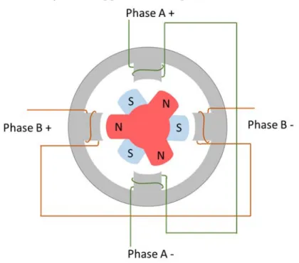
2.2 Schematic drawing of a simple hybrid stepper motor with 3 teeth and 2 phases . . . 10
2.3 Motor phase equivalent electrical circuit . . . 12
2.4 Motor phase high frequency equivalent electrical circuit including iron losses . . . 13
2.5 Forces applied to the motor axis . . . 14
2.6 Electromagnetic torque generated for a specific set of reference currents . . . 15
3.1 Rack, collimator and the cable connecting them . . . 18
3.2 Measured phase currents . . . 21
3.3 Measured motor-side currents . . . 21
3.4 Measured common-mode phase current. . . 23
3.5 Measured motor-side voltage. . . 23
3.6 Measured rotor angle and speed stepping in half-step mode. . . . 25
4.1 2-port T-net cable model connected to motor phase . . . 28
xiv List of Figures
4.2 Comparison of Gerr(s) transfer function for two different cable
lengths: 100 m and 1 km. . . 31
4.3 Motor phase current discrete controller . . . 33
4.4 Standard stepper motor drive scheme . . . 34
4.5 Connection of the DSP to the MOSFET h-bridges (not all the components represented) . . . 35
4.6 Drive board . . . 36
4.7 State machine diagram . . . 36
4.8 Programmed interrupts . . . 38
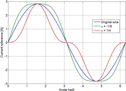
4.9 Third harmonic compensation current reference for the extreme values of α . . . 39
4.10 Typical motor phase current waveforms on the drive and motor side for a 720 m cable length . . . 40
4.11 Repeatability results for the SHS Star 2000, the modified SHS and the proposed drive . . . 41
4.12 Repeatability histograms for 1/4 stepping mode . . . 43
4.13 Repeatability histograms for 1/8 stepping mode . . . 43
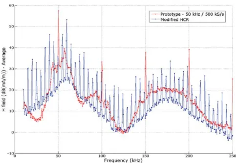
4.14 Low frequency spectrum of EMI emissions on drive side with a 720 m long cable. . . 44
4.15 The EMI test bench . . . 44
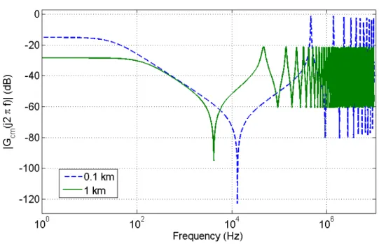
6.1 Bode magnitude diagram of Gcm(s) for two cable length extremes 55 6.2 Schematic view of drive, motor and cable . . . 56
6.3 The approximation ˆHest(s) and the exact expression Hest(s) for two cable lengths . . . 61
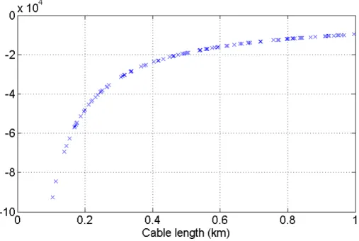
6.4 Real part of ˆHest(s)’s poles over a range of cable lengths . . . 61
6.5 Low frequency cable model connected to motor phase . . . 63
6.6 Comparison of the frequency responses ofHv(s) using the complete impedance expressions and the approximation, for two cable length extremes . . . 63
6.7 Simulation model structure. . . 65
6.8 True (dashed) and estimated (solid) states for a 1 km cable . . . . 70
6.9 True (dashed) and estimated (solid) states for a 1 km cable with mismatch; . . . 71
List of Figures xv
6.11 True (dashed) and estimated (solid) states for a 1 km cable at 150
step/s . . . 73
6.12 LHC Vertical Collimator . . . 76
6.13 Experimental test fixture . . . 76
6.14 Experimental test setup . . . 78
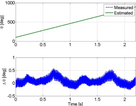
6.15 Position estimation (upper) and estimation error (lower) for a movement from out to in/beam . . . 80
6.16 Torque estimation (upper) and estimation error (lower) for a move-ment from out to in/beam . . . 80
6.17 Position estimation (upper) and estimation error (lower) for a trapezoidal movement . . . 82
6.18 Torque estimation (upper) and estimation error (lower) for a trape-zoidal movement . . . 82
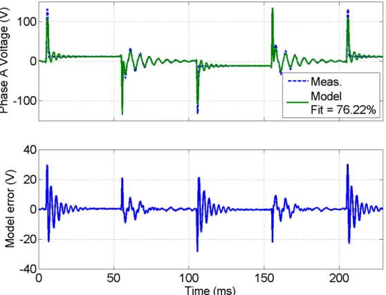
7.1 Discrepancy between measured voltage and standard model pre-diction.. . . 87
7.2 Measured (dashed) and fitted (solid) open phase voltages.. . . 92
7.3 Measured inductance at different positions. . . 93
7.4 Estimated and fitted ΨP M1 . . . 96
7.5 Holding torque measured for different RMS current values. . . 99
7.6 Estimated and fitted L.. . . 101
7.7 Model fit with the position dependent model. . . 102
7.8 Model fit with the current dependent model. . . 104
7.9 Model fit with the position and current dependent model. . . 106
7.10 Fit percentage of the models for different RMS current datasets . 108 7.11 EKF based closed loop control of the HSM. . . 111
7.12 Drive signals during closed loop operation. . . 112
7.13 Long term position estimation by EKF. . . 113
7.14 Comparison of EKF using different HSM models. . . 113
8.1 Full-step mode rotor position and speed acquisition. . . 116
8.2 Currents represented in the different frames . . . 121
8.3 Stepper Motor model diagram using the standardabreference frame121 8.4 dq frame Stepper Motor model diagram . . . 123
9.1 Decoupling scheme foridq. . . 125
xvi List of Figures
9.3 Simplified rotor speed loop . . . 127
9.4 Fit of the system step response to a first order system . . . 128
9.5 θm loop simplified . . . 128
9.6 FOC blocks scheme . . . 130
9.7 Full-step mode rotor position and speed acquisition, using
closed-loop position control . . . 131
9.8 Full-step mode step test in standard stepping mode. 10 repetitions
are done . . . 132
9.9 Full-step mode step test in FOC mode. 10 repetitions are done . 132
9.10 Stages of θ0 calibration . . . 134
9.11 Switch closed to open loop position stages . . . 135
9.12 Switch closed to open loop position search stage . . . 137
9.13 Switch closed to open loop position scheme . . . 138
9.14 Switch from closed to open loop position control in operation . . . 139
9.15 Zoom of the switch from closed to open loop position control in
operation . . . 139
9.16 Switch from open to closed loop position control in operation . . . 140
9.17 Zoom of the switch from open to closed loop position control in
operation . . . 140
9.18 Phase currents during a switch transition form closed to open loop,
irefd = 0A. The vertical scale is 1A/division . . . 141
9.19 Phase currents during a switch transition form closed to open loop,
irefd = 0.5A. The vertical scale is 1A/division . . . 141
9.20 Phase currents during a switch transition form open to closed loop,
irefd = 0.5A. The vertical scale is 1A/division . . . 142
9.21 LHC collimator linear stage . . . 143
9.22 Motor position in the collimator linear stage working in open-loop,
spring relaxed . . . 144
9.23 Motor position in the collimator linear stage using FOC, spring
relaxed . . . 144
9.24 Motor position in the collimator linear stage working in open-loop,
spring at the maximum compression . . . 145
9.25 Motor position in the collimator linear stage using FOC, spring at
the maximum compression . . . 145
List of Figures xvii
10.2 Output filter stages. . . 151
10.3 Typical two stage induction motor output filter. . . 151
11.1 Output filter adapted to a single stepper motor phase . . . 154
11.2 Simulation results for RDM =Z0 . . . 157
11.3 Zoom for the simulation results for RDM =Z0, motor side . . . . 157
11.4 Simulation results, motor side - Comparison of the proposed filter
and those for R0f =Z0 values . . . 158
11.5 Current in a motor phase with the output filter and a 720 meter
cable . . . 160
11.6 Closer view of the currents a motor phase with the output filter
and a 720 meter cable . . . 160
11.7 Motor side voltage with the output filter and a 720 meter cable. 162
11.8 Motor side voltage with 720 meter cable . . . 162
11.9 Repeatability results showing steady state position error histogram for the SHS Star 2000 drive with a short cable and without the
output filter. . . 163
11.10Repeatability results showing steady state position error histogram
for the SHS Star 2000 drive with a 720 meter cable and with the
proposed output filter. . . 163
11.11Low frequency spectrum of the EMI emissions for the SHS drive . 164
B.1 CINEL stepper motor based goniometer working principle . . . . 177
B.2 CINEL stepper motor based goniometer prototype . . . 177
B.3 CINEL stepper motor based goniometer 3D model . . . 177
B.4 Crystal platform position with standard stepping mode - one step
applied . . . 179
B.5 Crystal platform position with standard stepping mode - 1 µrad
steps . . . 179
B.6 Crystal platform position with FOC - 1 µrad steps . . . 179
B.7 Crystal platform positioning comparison - continuous motion . . . 180
B.8 CINEL Piezo based goniometer scheme . . . 181
B.9 CINEL Piezo based goniometer. Horizontal version (left) and
ver-tical version (right) . . . 181
B.10 CINEL Piezo based goniometer internal picture . . . 182
xviii List of Figures
List of Tables
2.1 Maccon stepping motor parameter values . . . 16
2.2 Cable parameter values . . . 16
4.1 Repeatability test comparison without a long cable connecting the
motor . . . 40
4.2 Repeatability test comparison with modified commercial drive and
a long cable connecting drive and motor . . . 41
4.3 Repeatability performance in different stepping modes . . . 42
6.1 Parameter values . . . 78
6.2 Results for continuous movement from out-to-in . . . 79
7.1 Parameters estimated for the standard hybrid stepping motor
elec-tric model . . . 86
7.2 Magnitude for the first four harmonics of the motor induced
volt-ages when no current is flowing in the phases. . . 91
7.3 ΨP M1 terms resulting from different current levels. . . 94
7.4 Inductance terms resulting from different current levels. . . 100
7.5 Parameters estimated for the position dependent model . . . 102
7.6 Parameters estimated for the current dependent model . . . 103
7.7 Parameters estimated for the position and current dependent model106
7.8 Performance of the different models comparing fit and average
computing time . . . 107
7.9 EKFs Comparison . . . 111
11.1 Filter component values. . . 156
11.2 Repeatability test results. . . 161
xx List of Tables
B.1 Overshoot and standard deviation comparison between stepping mode and FOC . . . 178
B.2 Standard deviation of the parasitic yaw in the rotational stage in
List of acronyms
ADC Analog to Digital Converter
AC Alternating Current
CERN European Organization for Nuclear Research
CM Common-Mode
CPU Central Processing Unit
DAQ Data AcQuisition
DC Direct Current
DM Differential-Mode
DSC Digital Signal Controller
DSP Digital Signal Processor
DTC Direct Torque Control
EKF Extended Kalman Filter
EMC Electro-Magnetic Compatibility
EMF Electro-Motive Force
EMI Electro-Magnetic Interference
FOC Field Oriented Control
HSM Hybrid Stepper Motor
IEC International Electrotechnical Commission
IGBT Insulated-Gate Bipolar Transistor
IIR Infinite Impulse Response
LHC Large Hadron Collider
LINAC Linear particle accelerator
LTI Linear Time-Invariant
LVDT Linear Variable Differential Transformer
MDC Motion Drive Control
MOSFET Metal Oxide Semiconductor Field-Effect Transistor
NRMSE Normalized Root Mean Square Error
xxii List of Tables
PCB Printed Circuit Board
PMSM Permanent-Magnet Stepper Motor
PRS Position Readout and Survey
PWM Pulse Width Modulation
RAM Random Access Memory
RMS Root Mean Square
RMSE Root Mean Square Error
Part I
Chapter 1
Introduction
This chapter introduces the framework and organization of this thesis. The work
has been carried out at CERN, the European Organization for Nuclear Research,
an organization devoted to the study of particle physics and operating the largest
laboratory in the world with this mission.
CERN is situated on the French-Swiss border (Figs. 1.2 and 1.3), close to
the city of Geneva. It was inaugurated 60 years ago as an effort for international
collaboration after the Second World War and it is composed of over 20
mem-ber countries of which Spain is part and more than 40 countries in cooperation
agreement, observers or in the process of joining.
1.1
The Large Hadron Collider
The Large Hadron Collider (LHC) (Fig. 1.4) is the latest addition to the CERN’s
accelerator complex (Fig. 1.5). It is a circular particle accelerator and collider,
the largest and most powerful in the world, with a length of 27 km and built 100
meters underground.
The LHC was designed to collide hadron beams, protons and lead ions
specif-ically, with an energy up to 7 TeV each beam, with the purpose of verifying the
Standard Model, the current framework for particle physics.
Inside the collider two proton beams are accelerated in opposite directions at up to 99.99 % of the speed of light, and they collide in four interaction points,
known as experiments, where the collision data is acquired for later study by the
particle physicists. To make this possible, the superconducting magnets in the
LHC must be cooled down to its working temperature, 1.9 Kelvin (-271 degrees
1.1. The Large Hadron Collider 3
Figure 1.1: CERN logo
4 Chapter 1. Introduction
Figure 1.3: Aerial view of the Large Hadron Collider area with the cycle of the CERNs accelerators highlighted
Celsius approximately) in order to use the superconducting properties of the conductors. The LHC has already collided protons with an energy of 8 TeV,
4 per beam, and is currently in the so-called Long Shutdown 1, with works for
upgrading it to work at its maximum energy.
In order for the LHC to work several historical accelerators at CERN are used
in chain. The protons are produced and accelerated in the LINAC-II, a linear accelerator, and then they are accelerated in steps, first in the Booster, then the
Proton-Synchrotron, the Super Proton-Synchrotron, and finally the LHC.
1.2
The Collimation system
The transverse energy density of the nominal beam in the LHC is 1000 times
higher than that previously achieved in proton storage rings, reaching values up
to 350 MJ for the 2 beams at the time. The energy in the two LHC beams
is sufficient to melt almost 1 ton of copper. Tiny fractions of the stored beam
suffice to quench a super-conducting LHC magnet or even to destroy parts of the
accelerator.
To stop and absorb the energy from the particles that, expectedly or not,
1.2. The Collimation system 5
Figure 1.4: Picture in the LHC tunnel
6 Chapter 1. Introduction
beam cleaning system composed of over 100 collimators located around the LHC ring and the transfer lines, which protects the machine against beam losses and
clean the beam of its halo.
Each collimator (Figs. 1.6 and1.7) is based on two jaws of different materials
that can move into the particle beam with a specified tilt angle, thanks to four
stepping motors. The jaws are bars made of specially selected materials capable
of receiving such impacts, such as carbon-carbon and graphite. These bars are
able to move horizontally and vertically, depending on the type of collimator, to
adjust the space between them and the beam.
This thesis work has been devoted to the modelling and control of the hy-brid stepping motors used to move the jaws of the collimator. In chapter 3 the
problems arising from the use of this electrical motor type in the accelerator
environment is described in detail.
1.3. Thesis organization 7
Figure 1.7: Half 3D cut of a collimator
1.3
Thesis organization
The organization of the thesis is presented in Fig. 1.8. Each part is described now:
• Part I is common to the whole thesis. It is dedicated to introducing its framework, presenting the motivation and formulating the problem that is
dealt with, and presenting the previous and initial work upon which the
thesis is developed.
• PartII first introduces sensorless state estimation for electrical motors and the state of the art of sensorless state estimation of Hybrid Stepper Motors
(HSM). Then the application of the Extended Kalman Filter (EKF) to
HSM driven through long cables is proposed and tested in simulation and
experimentally. After this an extension of the HSM electrical model apt for
real-time control and estimation is proposed and validated.
• Part III describes the state of the art of closed-loop position control for stepper motors. The option selected, Field Oriented Control (FOC), is then
detailed, as well as its structure, implementation and tuning. A switch from
8 Chapter 1. Introduction
the problem of reliability in the collimation system and improving the drive performance.
• PartIVpresents a different approach to the problem of HSM driven through long cables, by using power output filters to solve the problem created by
the application of high frequency signals to transmission lines.
• Part V, common for the whole thesis, summarises all the work done on the modelling and control of stepper motors in radioactive environments, and
presents the overall conclusions.
Chapter 2
Hybrid Stepper Motors
2.1
Introduction
In section 1.2 it was mentioned that stepper motors are the actuator chosen to
move the collimator jaws. This choice is based mainly on the fact that this kind
of motor does not need position feedback to work with a relatively high accuracy,
in addition to their great toughness, an essential feature in the given operating
conditions.
Stepping motors are a well known solution for many industrial and consumer
applications, with excellent literature describing them in detail (see [1] and [36]), and therefore only a brief introduction and model description of the type chosen,
the hybrid stepping motor (Fig. 2.1) with 2 phases, is done now.
These motors offer a high holding torque and therefore are common in
appli-cations where the movement is held at static positions or varies in discrete steps.
Moreover, despite usually being driven in open-loop position control, they have
non accumulative positional error and are capable of accurate positioning since
both stator and rotor have a series of teeth that tend to align in a specific known
position when the proper current configuration is applied to the motor phases.
Their toothed structure allows a mechanical turn to be divided into many
electrical turns, and therefore as the stepping sequence goes in predetermined
phase currents, the motor moves through these electrical turns and at the same time through the mechanical turn. In Fig. 2.2an example of a simple HSM, with
only 3 teeth, is presented. As the currents are applied in the proper sequence in
the motor phases, namely Phase A and Phase B, the north and south poles of
the rotor align with one or other phase, producing the rotation.
10 Chapter 2. Hybrid Stepper Motors
Figure 2.1: Hybrid Stepper Motor separated rotor and stator
2.2. Motor model 11
Many of the applications involving long cables to connect the motor either do not have precise positioning requirements or have the possibility of closing
the loop on the shaft position with sensors such as encoders. Nevertheless when
the motor is situated in harsh environments, it is not possible to use electronic
sensors and achieve a high robustness.
Particles accelerators use positioning systems in multiple different applica-tions, including collimators, movable targets, beam dumps and scrapers. Hybrid
stepper motors are often used as the actuators in these applications. These
mo-tors, and their electronic drivers, are subject to a number of requirements that
are relatively unique to accelerators. This is the case of the collimators in the
LHC.
2.2
Motor model
The motor model can be separated into two sub-models, an electrical and a
mechanical model. These have different time constants; the electrical model
having faster dynamics.
2.2.1
Electrical model
Each of the two electrical phases of the stepper motor can be modelled at
rel-atively low frequencies and currents as an RL circuit plus a back electromotive
force (emf), as in Fig. 2.3. This circuit is described by the following equation:
Lwdij(t)
dt =−Rwij(t)−ej(t) +uj(t) for j =A, B (2.1) where Rw is the phase resistance,Lw the phase inductance, ij the phase current,
uj the terminal voltage and the back emf voltages are described by:
eA(t) =−Kmωmsinpθm (2.2)
eB(t) = Kmωmcospθm,
with Km being the motor constant, p the number of motor pole pairs, ωm the
12 Chapter 2. Hybrid Stepper Motors
transform of Eq. (2.1), we find:
Ij(s) = 1
Zmot
(Uj(s)−Ej(s)) for j =A, B
and
Zmot(s) = Lws+Rw (2.3)
is the motor’s electrical impedance.
High frequency motor phase model
In order to get the transfer functions involving Zmot in the following chapters, an
accurate model of the motor phase impedance is needed. A simple RL model of
the motor phase impedance is not adequate for high PWM frequencies since the
ferromagnetic components of the motor phase circuit have losses that are strong functions of the frequency.
The high frequency equivalent circuit, like the commonly adopted equivalent
circuit of transformers (see [33]), has an iron-losses resistance, that models the
dissipated active power, in parallel with an equivalent inductance, which has a
value that is considerably lower than the nominal DC value. The presence of an
iron-losses equivalent resistance has the effect of introducing a pole in the high
frequency model of the motor phase impedance:
ZmotHF = Rw+sLeq 1 +sτp
(2.4)
2.2. Motor model 13
where Leq is the equivalent of Lw and Lf e in parallel:
Leq =
Lf eLw Lf e+Lw
and
τp = Rf e
Leq (2.5)
as in [52], whereRf e and Lf e are the resistance and inductance of the core losses
modelling shown in Fig. 2.4.
2.2.2
Mechanical model
The mechanical part of the motor is modelled as a rigid body subject to various
torques, as shown in Fig. 2.5:
Jdωm
dt =τem−Bωm−τdm−τl (2.6)
where
τem =Km(−imotAsinpθm+imotB cospθm)
is the motor’s electromagnetic torque, J its moment of inertia, B the viscous
friction coefficient,
τdm=Tdmsin(2pθm+φ)
is the detent torque, Tdm the detent torque amplitude, φ a phase shift associated
with τdm and τl the external load torque.
14 Chapter 2. Hybrid Stepper Motors
It should be mentioned that the frequency of the motor’s detent torque is taken as the electrical frequency’s second harmonic since this was observed
experimen-tally to be dominant for the motors used in the tests in [50]. This dominance
of the second harmonic, over the theoretically predicted fourth, has been found
elsewhere for hybrid stepper motors [88]. No loss of generality occurs, however,
by modelling the detent torque as such and the proposed approach is equally
valid for motors with different dominant detent torque harmonics.
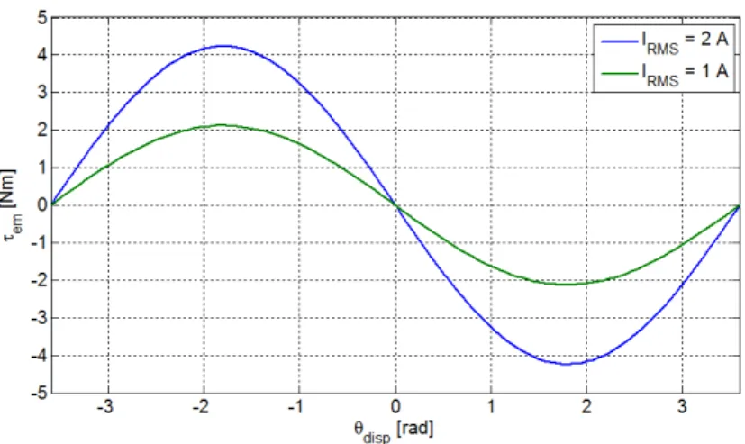
When a specific set of reference currents is applied, the rotor magnet tends to
align with the field generated by the motor phases. The electromagnetic torque
as a function of the displacement angle between the rotor and the angle of the field generated, θdisp, is shown in Fig. 2.6, for two different IRM S current values.
From this figure, we can see that if the rotor angle is behind the field generated,
a positive electromagnetic torque results, pushing the rotor to align with the
field. It can be also inferred that there is a static error when a external load is
applied, since the rotor position resulting is the angle whereτem compensates for
the applied load.
2.3. Collimator motor and cable used in the collimators 15
Figure 2.6: Electromagnetic torque generated for a specific set of reference cur-rents
2.3
Collimator motor and cable used in the
col-limators
The parameters defining the motor and cables used in the LHC collimators are
described here for reference.
The motor is a Maccon Hybrid Stepper Motor, with two phases, bipolar,
p = 50 teeth, a rated current of 2 A RMS and holding torque of 3.5 Nm. The
parameter values are summarized in Table 2.1.
The cable is a 24 twisted pair, multiwire cable. Its parameters were measured
16 Chapter 2. Hybrid Stepper Motors
Table 2.1: Maccon stepping motor parameter values
Parameter Value
Rw 3.2[Ω]
Lw 30[mH]
Nominal current (IRM S) 2 Amps RMS
Number of teeth (p) 50
Physical step size 1.8 degrees
Km 1.75[N m/A]
J 1.3×10⁻⁴[kgm2]
B 0.05[N ms/rad]
Tdm 0.1505[N m]
φ 0[rad]
Table 2.2: Cable parameter values
Parameter Value
r 23.0 [Ω/km]
c 48.9 [nF/km]
l 0.6 [mH/km]
Chapter 3
Problem Formulation
3.1
Introduction
The collimators, presented in section 1.2, are located in highly radioactive areas
due to the task that they perform.
This condition prevents the use of any electronics close to them, such as most
sensors, the microcontrollers and computers running the control algorithms or
the power electronics feeding the actuators that move the collimator jaws. Two
important consequences of this fact are:
• The electronics involved in the control and supplying of these systems are installed in radiation free areas up to 800 meters away. This means that the
actuators are connected to their drives by cables of this length as illustrated
in Fig. 3.1. Modern drives are usually based on switched inverters. Long
cables behave as transmission lines when switched voltages, containing high frequency components, are used.
• Position feedback for the motion control loop is limited to radiation hard sensors. In addition, the harsh conditions withstood by the collimators
make any intervention to repair or replace any sensor or part difficult and
expensive. Therefore, relying only on sensing feedback is preferably avoided.
The need to work without position feedback led to the choice of stepper motors as actuators in the collimation system. The two characteristics that make them
a great match for the application are their relatively high accuracy in open loop
control, eliminating the need for position feedback and their robustness, avoiding
frequent maintenance.
18 Chapter 3. Problem Formulation
Figure 3.1: On the left side an electronic rack and a drive, in a radiation safe area, on the right the collimator with the motors in the accelerator tunnel, in highly radioactive areas, and on the middle the cable connecting them
In the following sections the consequences of the use of long cables with
switched signals and stepper motors without position feedback is explained in
detail.
3.2
Use of switched drives with long cables
Most stepper motor applications do not require long cables to transfer power to
the motor. However, certain applications, such as in radioactive environments
in particle accelerator complexes (e.g. the LHC at CERN) and nuclear power
plants, or underwater applications, exist where the motor has to be located far
from its power drive. These cases cannot be dealt with directly by most of these
switched motor drives. The long cables, when high frequency PWM signals are
applied, behave like transmission lines, leading to different problems preventing
the motor drives from working appropriately.
Modern electric motor drives work mostly with discrete switches to improve efficiency compared to linear power supplies, feeding the phases of the motor
with PWM voltage waveforms of high frequencies compared to the mechanical
and electrical bandwidths of the motor, and high voltage amplitudes compared
3.2. Use of switched drives with long cables 19
This behaviour is normally acceptable since the phase of the motor is basically an inductor, and so it acts as a low pass filter for the current when the pulsed
voltage is applied.
However, in the described cases where long cables are used, different effects arise. This situation has been studied in the general literature of transmission
lines ([59]) and specifically when power motor drives are connected to AC
mo-tors. The effect and sizing of this phenomenon is shown in [37], where the most
relevant cable and motor parameters are studied with specific focus on the over
voltages produced on the side. The critical parameters leading to
motor-side voltages over twice the bridge voltage are also found. In [60] high frequency
models of a cable and motor combination are presented.
In [25] the problem generated in the motor insulation is studied. The short
rise time of technologies like MOSFET and IGBT combined with the high voltage
used, produces such a high du/dt, the derivative of the voltage applied to the
phase with respect to time, that the winding of the motor phase is equivalent to
a network of capacitors, and therefore at switch on time the voltage is held by the first few turns, leading to turn-to-turn insulation damage.
Nevertheless, very little literature describing the use of stepper motors with
long cables exists, to the author’s knowledge, though the control problem is con-sidered in [52, 53], where the motor-side current is estimated from the drive-side
current, and the current control loop is closed on this estimation. Details of this
work are given in chapter 4, as it is the starting point of the present thesis.
Now the most important effects on each part of these systems is detailed.
When a pulsed voltage is applied to a long cable, the cable acts as a transmission
line and, depending on the PWM chopping frequency, three important problems
can arise: drive-side current, common-mode current and motor-side voltage.
3.2.1
Drive-side current
The first problem occurs at the drive-side of the cable, where a ringing phenomena
in the current appears. This ringing effect is shown in Fig. 3.2, where a 20 kHz
PWM voltage with 120 V amplitude and fixed duty cycle is applied to a motor phase through a 720 meter cable. The motor and cable used are the same models
as the ones used in the LHC, described in section 2.3. In this case, the main
ringing effect occurs at the 3rd harmonic of the PWM frequency, 60 kHz. This
20 Chapter 3. Problem Formulation
cable and the output impedance of the drive, the latter being much smaller than the former, and causing big current oscillations for negligible oscillations on the
voltage.
The drive-side current can have large amplitude oscillations, over twice its mean value, and high frequency content, mainly at the harmonics of the PWM
signal, depending on the cable length and characteristics. Some motor drives
do not close the loop on the phase current, and therefore they do not have a
problem with this phenomena though over-current warnings may be triggered.
Many modern drives do, however, use current feedback control in order to achieve
faster dynamics. Normally it then is a problem to deal with this current, specially
with threshold based regulators such as hysteretic regulators, where the ringing
on the current would trigger the controller comparators when the actual current
in the motor is still far from the reference one. Dynamical controllers may work due to their frequency shaping action that can strongly attenuate the ringing
components, which are high frequency components with respect to the normal
closed loop bandwidths of the motor phase current.
One of the drives used during this work with a hybrid stepper motor is a
commercial switched drive with a nominal RMS current of 2 A. In Fig. 3.3
it can be seen how using this drive the currents in the motor phases are far
from the reference value when a 720 meter cable is used. This occurs because the
comparators in the drive, which compare the current with the reference threshold,
use the oscillating drive-side current, resulting in false detections of the current
overcoming the reference and thus applying an erroneous control action to the
cable.
3.2.2
Common-mode current
For ease of installation reasons, it is common to use multiwire cables when working with long cables, so that several motors can be driven via a single long cable. This
situation leads to the second problem, the cross-talk between phases and between
phases and shielding. This phenomena provokes an AC CM current in the phase.
This CM current is superimposed on the DM current to form the one shown in
Fig. 3.2.
These currents have two main negative effects. Firstly, as mentioned before,
the current controller comparators may be triggered by current spikes, just like
3.2. Use of switched drives with long cables 21
Figure 3.2: Measured phase currents. Blue: drive-side current, green: motor-side current
22 Chapter 3. Problem Formulation
fixed duty cycle, 120 V, 20 kHz PWM voltage through a 720 meter, 24 twisted pair, shielded, multiwire cable is shown. The current peaks in this case exceed
1.5 A, which may suffice to trigger the controller comparators when they should
not.
Secondly, a CM current fed to a long cable produces significant EMI emissions,
creating EMC problems. The consequences of CM currents and EMI emissions
generated in motor applications have been addressed in [81] and [32].
3.2.3
Motor-side voltage
The third problem, at the other extreme of the cable, is the voltage across the
motor terminals. In this case, the impedance of the motor at high frequencies is
much higher than the characteristic impedance of the cable, causing big
oscilla-tions in the voltage for small oscillaoscilla-tions on the current.
Depending on the combination of cable length, voltage rise time and PWM
frequency, the oscillations may reach or even exceed twice the applied voltage in
the drive-side of the cable. These oscillation also have relatively high frequency,
that of the PWM frequency and its harmonics.
This effect may lead to insulation breakdown in the motor windings, due to the high voltage amplitude and derivative. Fig.3.5shows these motor-side oscillations
when a 120 V, fixed duty cycle, 20 kHz PWM voltage is applied through a 720
meter cable as the one used in the LHC collimators, described in section 2.3.
3.3
Use of stepper motors and open loop
posi-tion control
Hybrid stepper motors are often used as the actuators in positioning systems.
These are robust motors with a relatively high accuracy working in open loop
positioning. For this to be possible, they rely on a precise mechanical construction
and a high nominal electromagnetic torque. The nominal torque of the motor is
chosen at least twice the maximum expected torque in the application. In this
way, if this torque is not overcome, it can be assumed with a good confidence
that the motor is within a known bound of the desired position.
However, in the event of higher than nominal load torques, stepper motors can
3.3. Use of stepper motors and open loop position control 23
Figure 3.4: Measured common-mode phase current.
24 Chapter 3. Problem Formulation
of the motor’s position so that compensatory action can be taken to correct misalignments or lost steps. Rotary encoders and resolvers can both be used to
provide motor position feedback, but they both increase the positioning system’s
cost and reduce its reliability. In the case at hand, the situation is even worse
since on one side the sensors must be designed to be radiation hard and, on the
other, it is not affordable to reduce the overall reliability of the system. Sensorless
technology is, therefore, an attractive alternative.
In addition, stepper motors motion profiles are abrupt by nature. As their
name indicates, these profiles are stepped, and therefore high accelerations are
constantly applied. In Fig. 3.6 an example of the rotor’s angle and speed in a
sequence of steps in half-step mode is shown. It can be appreciated how the angle
has big oscillations, leading to high instantaneous speeds. In this example, for an
average speed of roughly 0.65 rads/sec, maximums of 16.4 rads/sec are reached.
This kind of motion profile is hard for the mechanics that are connected to
the motor, and mechanical degradation is unavoidable. For this reason, the use of sensorless technology is again desirable in order to estimate the mechanical
degradation of the collimators. This is possible thanks to the estimation and
monitoring of the torque applied by the motor during the motion.
During the validation tests of the collimator mechanics, tight margins are set
for the torque applied along the jaw motion range. If this torque changes during
the lifetime of the collimator, sensorless torque estimation would allow it to be
detected before a mechanical failure occurs, allowing for preventive maintenance
during the planned technical stops of the machine, instead of reactive maintenance
forcing a stop of the machine unexpectedly with the costs involved.
3.4
Purpose of the thesis
The purpose of this thesis work is to deal with the problems presented in this chapter.
The starting point is the work described in chapter 4. An algorithm to
esti-mate the rotor position and the applied load torque with long cables is proposed, in order to detect steps lost and perform mechanical diagnostics of the
collima-tor. It is developed and implemented in a real-time application. Improvements
in the state-of-the-art for real-time state estimation applied to electrical motors
3.4. Purpose of the thesis 25
Figure 3.6: Measured rotor angle and speed stepping in half-step mode.
Then, the Field Oriented Control or Vector Control method is investigated
for its use in position control of hybrid stepper motors and implemented in our
application. The purpose of this is to smooth the aforementioned abrupt
mo-tion profile present in stepper motors ir order to reduce vibramo-tion and improve mechanical lifetime. The result of several applications are presented. However,
position feedback is needed for this type of control, and it is not desirable to rely
on position sensors for the collimator control. A means to use these sensors whilst
maintaining the reliability of the system in case of sensor failure is necessary.
To tackle the long cable problem a power approach can be taken, manipulating
the actual cable-motor system before attempting to close the current loops. This
is done with the proposal of output filters for stepper motors. Output filters are a
standard solution for AC motors working with long cables in industry. However,
Chapter 4
The Stepper Motor Drive
4.1
Introduction
This work started over the base of some previously developed work in the same
project line. In the first part of this chapter, the aforementioned work is described,
in order to give a better understanding of the context. In the second part the
DSP Drive developed and used for the experimental validation during the thesis
is presented.
4.2
Previous work
Analog solution
The first step in the bigger goal of controlling the collimator jaws position with
high precision was to have a stepper drive able to work with long cables, up to 1
km. As presented in section 3.2, commercial PWM drives cannot work properly
with cables of this length due to the high current ringing, and therefore a solution
to overcome this problem was necessary.
This was achieved by a collaboration between CERN engineers and a private
company to produce a modified version of one of their commercial drives, the SHS Star 2000.
This drive works at 20 kHz PWM chopping frequency and 135 V DC link
voltage. It uses a non-linear control algorithm implemented with a state machine
that applies a fixed frequency PWM with a minimum Ton time, i.e. the time
where the voltage applied to the motor phase is the voltage of the power supply
4.2. Previous work 27
used in the H-bridge, and uses a comparator which controls the PWM width, switching off the voltage applied if the current overcomes the reference and the
minimum Ton has been applied.
It has been designed to work with up to 1 kHz equivalent closed loop
band-width. This value has to be taken carefully since the concept of closed bandwidth is applicable only to linear systems. However, it gives a good idea of the response
speed in closed loop of the system.
The solution developed is explained in detail in [19]. In consist on the use of a filtered version of the drive-side current by means of an analog filter implementing
an estimation transfer function which from the drive-side measurement would
provide the motor-side current estimation, and with this estimation the current
loop could be closed.
This solution was implemented and it is the present solution working in the
LHC [53]. However, it has several limitations. The values for the analog filter
estimator where fixed by resistors in a board externally attached to the drive.
This means that only motor side currents for some discrete cable lengths, of a
specific cable type, could be estimated properly.
In addition, one of the main issues of drives when used in large installations
such as the LHC is the emitted electromagnetic field. It can potentially generate
interferences with very sensitive equipment installed either directly in the
tun-nel, since the cables run for hundreds meters all around the tuntun-nel, or in racks
mounted in suitable zones in order to be protected from ionizing radiations.
The most critical emitted frequencies from the power cables lie at the low end
of the spectrum. Increasing the PWM frequency upwards has the double
advan-tage of reducing the current ripple in the motor phase and potentially producing
less powerful emissions in the low frequency range. To accomplish this, there has
to be no subharmonics generated. Nonlinear and hysteresis current controllers cannot guarantee this constraint whereas fixed PWM period linear controllers do
not have this drawback.
This fact lead to the proposal of a fully digital version of the drive in which
the filter and controller could be calculated from the cable parameters and length, measurable from the drive with a simple test. The new controller to be
imple-mented in this drive shall be a linear one, since it will avoid the generation of
sub-harmonics of the chopping frequency and it can be made cable length
28 Chapter 4. The Stepper Motor Drive
Digital solution
In [19] the first version of a 5th order digital estimation filter is proposed, based
on the Taylor expansion of the hyperbolic functions that define the transmission
line behaviour (details of this model are given in the following sections). In [52] an improved version, a 5th order filter based on a balanced Pad´e approximation
to the hyperbolic functions is used. In [27], a similar approximation is used, but
applied to the final transfer function relating drive-side and motor-side currents,
instead of to the hyperbolic functions independently. In the latter approximation
the order is reduced to 2nd instead of 5th as in the previous ones, after careful
testing of the best estimation performance.
The motor-side current estimation scheme developed in the aforementioned
work is explained next.
4.2.1
Motor-Side Current estimation scheme
Motor and cable model
When the motor phases are connected to a long cable, the behaviour of the
system changes and therefore the model must be updated to include it. The
electrical model includes now a transmission line between drive and motor while
the mechanical model is unaffected by the presence of the cable.
The connecting cable can be represented by an equivalent 2-port T-net model.
Using this model, each phase of the motor with its cable can be represented as
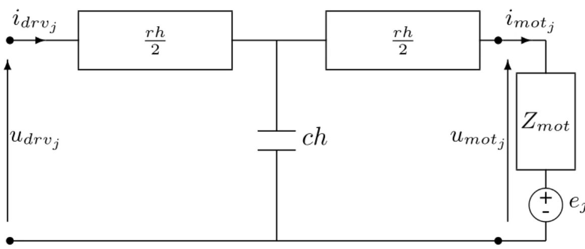
in Fig. 4.1.
4.2. Previous work 29
The three new impedances introduced are given as:
Zt1(s) =Zt2(s) =Z0(s) [coth(γ0(s)h)−csch(γ0(s)h)] (4.1)
and
Zt12(s) = Z0(s)csch(γ0(s)h) (4.2)
where
γ0(s) =
p
(r+sl) (g+sc)
is the propagation coefficient and
Z0(s) = s
r+sl
g+sc
is the characteristic impedance with h being the cable length,r,l,g and cbeing
the resistance, inductance, conductance and capacitance of the cable per unit
length respectively.
The electrical model for the cable and motor combination now links the
drive-side current in phase j, idrvj, to the drive-side voltage in phase j, udrvj, and, in
the Laplace domain, is given by:
Idrvj(s) = Gcm(s)Udrvj(s) +Hcm(s)Ej(s) (4.3)
where
Gcm(s) =
1
Zt1 +Zt12||(Zt2+Zmot)
(4.4)
= Z0cosh(γ0h) +Zmotsinh(γ0h) Z0[Zmotcosh(γ0h) +Z0sinh(γ0h)]
and
Hcm(s) =
Zt12
Zt1+Zt12
−1
Zmot+Zt2+Zt1||Zt12
(4.5)
= −1
Zmotcosh(γ0h) +Z0sinh(γ0h)
.
Note that the s dependence has been and will be omitted in some equations
30 Chapter 4. The Stepper Motor Drive
The De-Ringing Filter
In order to virtually eliminate the effects of the transmission line on the control
signal the motor-side current has to be estimated from the only measurable signal
available, the drive side current. To accomplish that it is possible to apply the
current divider rule to the circuit shown in Fig. 4.1. The motor current can be
evaluated by superposition as follows:
Imotj =
Zt12
Zt12+Zt2+Zmot
Idrvj−
1
Zt12+Zt2+Zmot
Ej (4.6)
By means of the transmission lines equations (4.1) and (4.2), it is possible to
write the following expression:
Imotj =
Z0
Z0cosh(γ0h) +Zmotsinh(γ0h)
Idrvj−
sinh(γ0h)
Z0cosh(γ0h) +Zmotsinh(γ0h)
Ej
=GestIdrvj −GerrEj (4.7)
Note that Gerr and Gest are symbols for transfer functions, not conductances
specifically, even though Gerr has the dimensions of one.
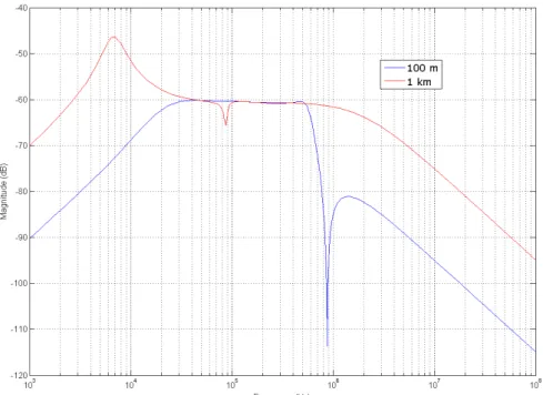
Now the estimation error, I(s) = Gerr(s)E(s), should be evaluated. For
hybrid stepping motors, the back electromotive forces of the motor phases are
given in (2.2). Even for this type of motors, which have a high value of Km, the
maximum value of the back electromotive force is generally limited to few tens
of volts since they are best suited to low speed applications. Gerr(s) can now be
evaluated and the results shown in Fig. 4.2 for the motor and cable parameter
values reported in tables 2.1 and 2.2, confirming that the estimation error I(s)
can be safely neglected for cable lengths of 1 km or even more. Indeed, even
considering the worst case in whichGerr(s) has a maximum, the amplitude of the
back emf at that frequency range is very limited so the attenuation due toGerr(s)
can be reasonably considered greater than 60 dB. This means that the motor-side
current can be directly estimated from the drive-side current with good precision
by applying Gest(s) to Idrv.
4.2.2
Controller design
A linear controller that, at each PWM fixed period, sets the duty cycle of the