A new test standard to evaluate the watertightness of window-wall
interfaces
ARCE RECATALÁ María
1, a *, GARCÍA MORALES
Soledad
1,band VAN DEN
BOSSCHE Nathan
2,c1Department of Construction and Technology in Architecture, Faculty of Architecture, Technical University of Madrid, Av. Juan de Herrera 4, 28040 Madrid, Spain.
2Department of Architecture and Urban Planning, Faculty of Engineering and Architecture, Ghent University, Jozef Plateaustraat 22, 9000 Ghent, Belgium.
a[email protected], b[email protected],c[email protected]
*corresponding author
Keywords: Window-wall interfaces, watertightness test standards, weathertightness performance,
water penetration resistance.
Abstract. Window-wall interfaces must be designed to prevent water ingress caused by all the
acting forces: kinetic energy of raindrops, surface tension, gravity action, pressure differences, capillary forces, local air currents and hydrostatic pressure. These connections are the primary areas of concern and an important source of problems in the building enclosure. They are designed by the architect or façade engineer, who is expected to follow the standards, sector documents and technical guidelines offered by the manufacturers. However, despite its importance, there is currently no test standard to assess the weathertightness performance of the installation of the window into the building envelope. Such a standard would not only offer a context for product testing, but also allow the development of more consistent guidelines for building practitioners and manufacturers. Currently available standards only provide testing procedures for the resistance to water penetration for window and door elements (EN 1027, static test sequence), and a generic test protocol for façade systems (EN 12865, cyclic wind pressure sequence).
In the framework of a research project for the Belgian Government, an overview of 30 watertightness test standards has been carried out, showing a large variety of approaches, parameters, test pressures, criteria… In this paper a state-of-the-art is presented on the test standards, which propose both laboratory and field procedures, the differences among laboratory standards are highlighted and discussed and the tests results are reported. Subsequently, a proposal is made for a new test standard for window-wall interfaces that balances the needs of the industry (practical constraints, simple and quick) and the requirements from an academic point of view (reliability and repeatability).
Introduction
The stages of product life during which testing principally occurs are: (1) product design and development; at the time of construction utilizing a “mock-up”, (2) recently installed products or (3) during their useful service life. In the early life stages of the fenestration product, testing is done to determine performance limits and to establish certification levels by means of an induced leakage (laboratory tests). In the middle-life stages, prior to the issuance of the building occupancy permit and no later than six months after the installation of the component, testing is for quality assurance. In the later life-stages, on-site components that are older than six months, testing is intended to reproduce actual leakage that has been observed during the in-service life of the installed fenes-tration product [1].
In this paper is presented an overview of the watertightness test standards, which propose both laboratory and field procedures. Subsequently, a discussion on essential elements of protocols is undertaken, reporting some tests results. Note that most standards have a pass/fail criteria based on a visual inspection of the specimen during the test duration. However, when testing porous materials this inspection becomes a little more complex. Finally, a proposal is made for a new test standard for window-wall interfaces, which is expected to describe a generic test protocol applicable to all types of window-wall interfaces and materials.
Overview of watertightness test standards
In the following lines a brief overview of the currently available watertightness test standards will be undertaken considering whether they are executed on field or in laboratory conditions and whether they are addressed to window units, wall units or the connections within window-wall interfaces. Note that the field of application is often not clearly stated in the scope.
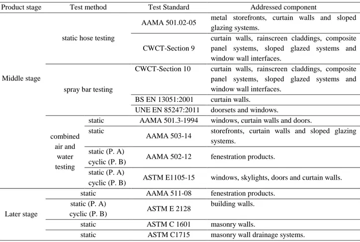
Field test standards. Field watertightness tests can be used to test windows, roofs, rainscreens,
walls and curtain wall systems for watertightness leakages in order to assess whether the manufacturing and installation of the component has not affected the performance of the system on the completed building (evaluate the impact of site workmanship). Table 1 exhibits a brief overview of the currently available European and American standards, the test method they propose and the addressed components in each case. This test protocol usually involves the spraying of water at a section of the façade at a specified rate using a specific apparatus and monitoring the test sample to ensure water does not penetrate through the enclosure system and checking window components including frame, seals, opening and closing sashes. Note that in the static hose testing method the specimen is not subjected to the conditions which simulate the effect of wind driven rain (WDR) and driving wind rain pressures (DWRP). In addition, it is intended to determine the resistance to water penetration of only those joints in the building envelope which are designed to remain permanently closed and watertight and is not applicable to joints between very porous components since they may become unrealistically saturated. Conversely, the spray bar testing method is suitable for open-jointed systems since the flow rate and pressure is controlled to give a continuous film of water to the face of the specimen, not forcing water into the joints.
Table 1. Overview of the currently available European and American site test standards.
Product stage Test method Test Standard Addressed component
Middle stage
static hose testing
AAMA 501.02-05 metal storefronts, curtain walls and sloped glazing systems.
CWCT-Section 9
curtain walls, rainscreen claddings, composite panel systems, sloped glazed systems and window wall interfaces.
spray bar testing
CWCT-Section 10 curtain walls, rainscreen claddings, composite panel systems, sloped glazed systems and window wall interfaces.
BS EN 13051:2001 curtain walls.
UNE EN 85247:2011 doorsets and windows.
combined air and
water testing
static AAMA 501.3-1994 windows, curtain walls and doors. static
AAMA 503-14 storefronts, curtain walls and sloped glazing systems.
static (P. A)
AAMA 502-12 fenestration products. cyclic (P. B)
static (P. A)
ASTM E1105-15 windows, skylights, doors and curtain walls. cyclic (P. B)
Later stage
static AAMA 511-08 fenestration products. static (P. A)
ASTM E 2128 building walls. cyclic (P. B)
static ASTM C 1601 masonry walls.
static ASTM C1715 masonry wall drainage systems.
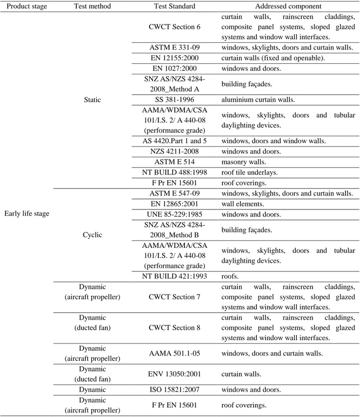
Laboratory test standards. Whereas field tests are useful to check the performance of on-site
Table 2. Overview of the currently available worldwide laboratory test standards.
Product stage Test method Test Standard Addressed component
Early life stage
Static
CWCT Section 6
curtain walls, rainscreen claddings, composite panel systems, sloped glazed systems and window wall interfaces. ASTM E 331-09 windows, skylights, doors and curtain walls.
EN 12155:2000 curtain walls (fixed and openable). EN 1027:2000 windows and doors.
SNZ AS/NZS
4284-2008_Method A building façades. SS 381-1996 aluminium curtain walls. AAMA/WDMA/CSA
101/I.S. 2/ A 440-08 (performance grade)
windows, skylights, doors and tubular daylighting devices.
AS 4420.Part 1 and 5 windows, doors and window walls. NZS 4211-2008 windows and doors.
ASTM E 514 masonry walls. NT BUILD 488:1998 roof tile underlays.
F Pr EN 15601 roof coverings.
Cyclic
ASTM E 547-09 windows, skylights, doors and curtain walls. EN 12865:2001 wall elements.
UNE 85-229:1985 windows and doors. SNZ AS/NZS
4284-2008_Method B building façades. AAMA/WDMA/CSA
101/I.S. 2/ A 440-08 (performance grade)
windows, skylights, doors and tubular daylighting devices.
NT BUILD 421:1993 roofs. Dynamic
(aircraft propeller) CWCT Section 7
curtain walls, rainscreen claddings, composite panel systems, sloped glazed systems and window wall interfaces. Dynamic
(ducted fan) CWCT Section 8
curtain walls, rainscreen claddings, composite panel systems, sloped glazed systems and window wall interfaces. Dynamic
(aircraft propeller) AAMA 501.1-05 windows, doors and curtain walls. Dynamic
(ducted fan) ENV 13050:2001 curtain walls. Dynamic ISO 15821:2007 windows and doors. Dynamic
(aircraft propeller) F Pr EN 15601 roof coverings.
Comparison of laboratory test standards
water-penetration testing: water application (which in itself is to be calibrated and set within certain boundary conditions) and the air pressure difference between the interior and exterior surfaces of the test specimen. Both variables have an impact on the kinetic energy of the water droplets and the pressure difference across the specimen (acting forces which cause water infiltration).
Conditioning of the laboratory and specimen. Most standards do not comprise specific
requirements in respect to the conditioning of the laboratory and neither the specimen. When some laboratory conditioning is considered, the regarded parameters are: the temperature of the water, the surface tension of the sprayed water, the temperature of the laboratory and the relative humidity of the laboratory. (1) Higher temperatures and contained (2) salts and/or (3) soap reduce the surface tension of the water droplet, becoming easier to wet the elements and get into pores and fissures rather than bridging them, then increasing the leaks in the specimen. Out of the three, soap has the most lowering effect. Salts also lower the surface tension of the water droplet, but after a point it stops influencing the surface tension.
Another parameter is the amount of time a sample should be stored in laboratory at those conditions prior testing. With the exception of EN 1027, the standards do not prescribe any time spell when are addressed to curtain walls, window or door sets. Note that EN 1027 establishes at least four hours of conditioning at specific laboratory conditions before testing. Nevertheless, the standards focused on absorptive materials such as masonry walls or roof tiles, a time spell of storage of the materials (at least five days) and the built specimen (fourteen days) in specific conditions is suggested (ASTM E 514).
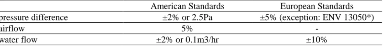
Apparatus. Although several standards recommend specific models of nozzles manufactured by
particular companies (AAMA 501.2-1994 and NZS 4211-2008), the normal practice is to suggest some guidelines in the devices required to conduct the watertightness tests depending upon the type and goal of the test. Usually, a standard comprises restrictions for the maximum tolerance in respect to producing airflow, water flow and pressure difference (see Table 3) and the maximum measurement uncertainty of the measuring devices.
Other considerations in the standards are the calibration of the water flow (a catch box test is proposed) and the cleaning of the nozzles prior to testing.
Table 3. Overview of the prescribed accuracies for the apparatus in the standards worldwide.
American Standards European Standards pressure difference ±2% or 2.5Pa ±5% (exception: ENV 13050*)
airflow 5% -
water flow ±2% or 0.1m3/hr ±10%
Setup - Specimen. All standards determine that the sample shall be representative in both size
and shape (usually the largest standard assembly or element in the product range), and has to undergo the same method of construction in lab as it will do in reality. The standards addressed to evaluate façade systems determine also that the materials of the test sample shall have the same constructive detail, flashing and anchorage as the building façade.
necessity of the sample’s surfaces to be clean and dry when testing is stressed, and the proper cure of sealants and drying of materials should also be considered.
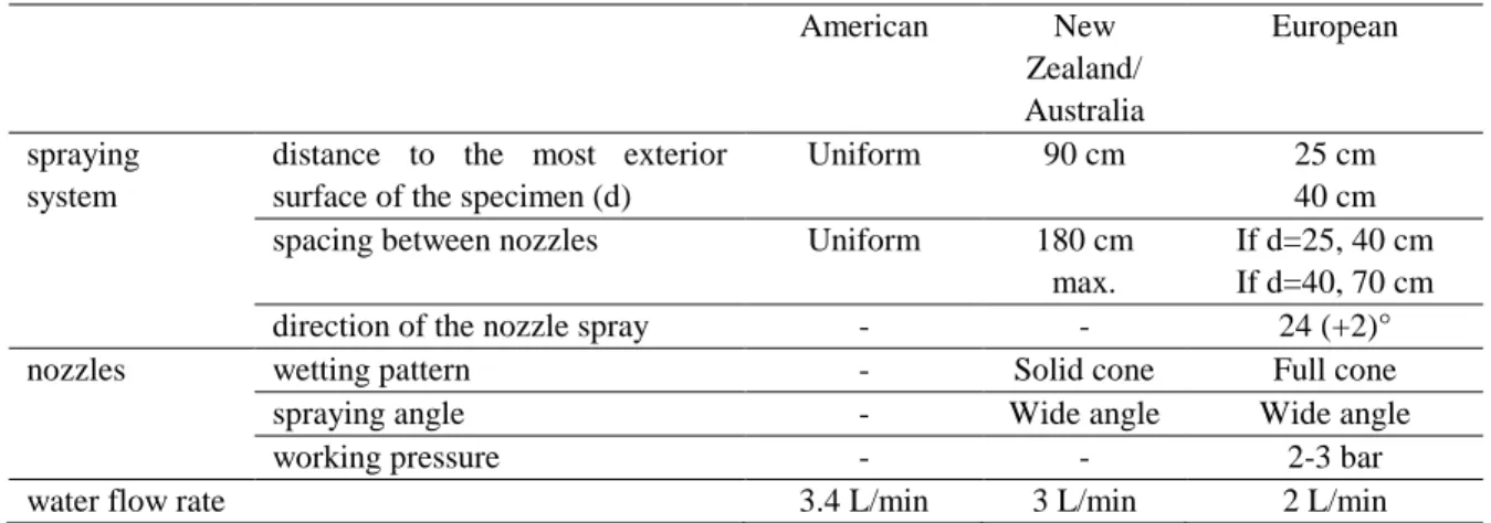
Setup - Spraying system. The most common practice is to propose a grid of nozzles evenly
spaced to spray the specimen. Some standards provide more detailed information on the technical features of the spraying system and nozzles. For instance, it is suggested the distance to the most exterior surface of the specimen, the spacing between nozzles, the direction of the nozzle spray, the wetting pattern of the nozzle, the spraying angle of the nozzle, the working pressure of the nozzle and the water flow rate (see Table 4). According to ASTM E547, spraying water at 3.4 L/min per m2 is equivalent to the direct impingement of rain on the wall at the rate of 203 mm/h.
Table 4. Technical specifications of the spraying system and nozzles in standards.
American New Zealand/ Australia
European
spraying system
distance to the most exterior surface of the specimen (d)
Uniform 90 cm 25 cm
40 cm spacing between nozzles Uniform 180 cm
max.
If d=25, 40 cm If d=40, 70 cm
direction of the nozzle spray - - 24 (+2)°
nozzles wetting pattern - Solid cone Full cone
spraying angle - Wide angle Wide angle
working pressure - - 2-3 bar
water flow rate 3.4 L/min 3 L/min 2 L/min
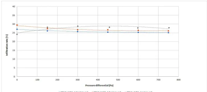
As stated by Spraying Systems Co., the higher the working pressure of the nozzle, the greater the force of the water impinging on the wall (the greater the kinetic energy of the water droplets). Drop velocity is dependent on drop size. Small drops may have a higher initial velocity, but velocity diminishes quickly. Larger drops retain velocity longer and travel further. Full cone nozzles, the ones suggested in the standards, have the largest drop size. So, for the same drop size range, what would define the worst case scenario: to spray water at a higher velocity with a lower volumetric flow rate or to spray water at a lower velocity with a higher volumetric flow rate. Would each one promote different kind of failures to the sealing elements of the window-wall interface? It is rather difficult to control the velocity of the water. The only thing that can be chosen is the type of nozzle, which according to the spraying rate will have a working pressure that will provide the water droplets with a specific kinetic energy load. The greater the working pressure, the bigger the kinetic energy load is. In such a case, two types of nozzles, QPHA-2.8W and QPHA-5.6W, were selected from the same company (Spraying Systems Co.) with two very different working pressures for a similar spray rate (see Table 5).
Table 5. Technical specifications of the nozzles.
Spray rate Nozzle type Working pressure (bar)
1.7 L/min per m2 QPHA-2.8W 1.8
1 L/min per m2 QPHA-2.8W 0.6
To evaluate the effect of the type of nozzle and volumetric flow, an experimental assessment was performed on an open joint cladding made of panels of fibrocement. The water infiltration rate into the air cavity through the 1 cm horizontal and vertical joints was measured by means of a gutter located at the bottom of the specimen. It was found that the choice of the type of nozzle had an impact on the percentage of infiltrated water, being more remarkable for lower pressure differences (see Fig 1). When statically comparing the test results of both nozzles for the same spray rate, the t Student analysis gave a P-value smaller than 0.0001 and the same happened with the F test analysis. It means that both, the mean and the variance of the two tests are significantly different. The graph also renders that the working pressure has a greater effect on the infiltration rate than the volumetric flow.
Figure 1. Water infiltration percentages in relation to the applied pressure differential and the type
of nozzle used in the test.
On the other hand, other European standards (e.g. EN 12865 and NT BUILD 421) make a distinction between simulating runoff (a bar of nozzles at the top with a flat spray pattern) and driving rain (a regular grid of nozzles with a circular full cone spray pattern). At each case a different water flow rate is suggested. For instance, the runoff rate is 1.2 L/min per linear meter and the driving rain, 1.5 L/min per m2 according to EN 12865. Therefore, if both are applied, the final result will be a regular grid of nozzles in which the first row will have a different water flow rate and spray pattern from the following rows of nozzles. Nonetheless, there is an exception. EN 1027 proposes a bar of nozzles if the specimen’s height is 2.5 m or fewer, and suggests adding a row of nozzles every 1.5 m when the height of the specimen is greater than 2.5 m. Note that a regular array of nozzles in a bar permits a reasonably even distribution of water across the entire specimen surface like a grid. However, the resulting water load of the grid arrangement, due to migration downward along the face of the cladding, increases in proportion to the wall height, locating the maximum effective load at the base of the wall [3].
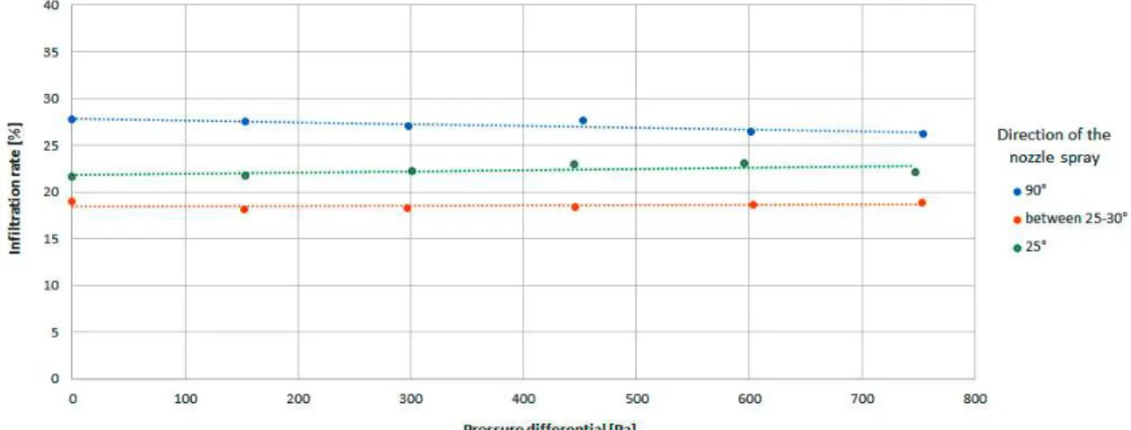
droplets acquire more kinetic energy and are able to reach longer infiltration distances. For instance, at the 30.5 cm-range, the pressure is about 7.0 psf (335.16 Pa), while at a distance of 10.16 cm, the pressure can reach 45 psf (2154.61 Pa). Additionally, angling the nozzle with respect to the test surface to focus on a glazing seal at a protruding mullion, for example, will increase the pressure at the intersection of the two test-surface planes [1].
To check the impact of the direction of the spray nozzle on the water infiltration rate across the specimen, several watertightness tests were conducted over the previous open joint cladding. Once again, the water infiltration rate inside the air cavity was collected through the 1 cm vertical and horizontal joints. The results of the tests are shown in Figure 2, and differences up to 10% are evident caused by the angle of the nozzle. Again, the results seem to indicate that the infiltration rate is not affected by the pressure difference. Note that these tests followed the same procedure and had the same spraying system and nozzles in all cases.
Figure 2. Water infiltration percentages in relation to the applied pressure differential and the direction of the nozzle spray.
Test procedure – Type of test. The resistance of wall elements to driving rain can be
determined with 4 types of watertightness test methods: static, cyclic, dynamic and wind tunnel testing. Up to now, there is only one draft standard that refers to the latter (FprEN 15601). Static pressure test methods prescribe a constant flow rate and a static pressure difference, which is stepwise augmented to assess the performance level of a component (e.g. EN 1027). Cyclic pressure test methods subject the test specimen to rapid pressure pulses (e.g. EN 12865), but always wetting the specimen first at ∆P=0 Pa. Contrary to the cyclic test methods, where the pressure fluctuation is carefully prescribed, the dynamic test protocols use an axial flow wind generator installed close enough to the test specimen to generate a turbulent flow field, while water droplets with kinetic energy are sprayed over the surface. It attempts to create more realistic conditions, although no publications which assess its representability and reproducibility have been found [5]. According to the standards, the turbulent flow can be generated by means of (1) an aircraft propeller (CWCT-Section 7, AAMA 501.1, F Pr EN 15601) or by (2) a ducted fan (CWCT-(CWCT-Section 8, ENV 13050). In (1) the wind flow is reproduced by a wind stream, whereas in (2) pressure difference pulses are applied as well.
terms of water ingress than the cyclic test conditions, when testing masonry walls (moisture buffer façades). Rainscreen claddings (pressure equalized systems) show higher water infiltration rates when are tested under static conditions than under cyclic conditions as well.
It is yet not clear which type of test procedure renders the most realistic, or worst test conditions. Some authors reported that face-sealed façades (water penetration control strategy) result in worse performance levels when they are subjected to cyclic test procedures. According to Van den Bossche et al. [6] and Van Goethem et al. [7], static pressure conditions are more unfavourable in terms of water ingress than the cyclic test conditions, when testing masonry walls (moisture buffer façades). Rainscreen claddings (pressure equalized systems) show higher water infiltration rates when are tested under static conditions than under cyclic conditions as well.
Test procedure – Applied pressure differences. In static test methods, some standards require
only one pressure difference level (the performance level) throughout the entire test (ASTM E514, ASTM E331, SNZ AS/NZS 4284, AAMA/WDMA/CSA 101/I.S. 2/ A 440), whereas in other standards, the pressure differential is stepwise augmented (CWCT, EN 12155, EN 1027, AS 4420.Part 1 and 5). In the latter type, the most common protocol in the European standards is to increase the pressure difference in steps of 50 Pa until 300 Pa, from which on in steps of 150 Pa.
In cyclic test methods, (1) the pressure difference steps and (2) their corresponding lower and upper limits of pressure for a pulse are provided in the standards. There are two differentiated trends regarding (2). Some standards establish the pressure pulses from 0 Pa up to the desired pressure differential, ∆P, (AAMA/WDMA/CSA 101/I.S.2/A440-08, ASTM E 547, EN 12865, EN 85-229, NT BUILD 421); whereas others start from a value different to 0 Pa and go to the desired ∆P (AS 4284-Method B and ASNZ 4284). Referring to (1), the American standards propose a single pressure differential step (ASTM E 547-09), whereas the Australian standards propose 3 steps (SNZ AS/NZS 4284-2008) and the European, one step every 150 Pa (EN 12865:2001 and NT BUILD 421:1993).
In the few dynamic test methods found, it is a common practice to demand only one pressure level throughout the entire test regardless of how they generate the turbulent wind flow. Only the one addressed to roofs proposes 5 to 10 pressure steps decrements (F Pr EN 15601).
Test procedure – Duration of the test. In static test methods where the specimen is subjected to
a single pressure level, the common practice is to impose a spell of 15 minutes without pressure difference. However, in the case of standards addressed to masonry walls (ASTM E514, ASTM C 1601, ASTM C1715) the duration of the test increases to at least 4 hours. This time period was found reasonable by Chew [2001]. He found that leakage rates generally started to stabilise from 3.5 h onwards when testing masonry walls.
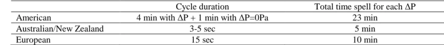
Regarding the cyclic test methods, two variables are set out: (1) the duration of the cycle and (2) the time spell of each pressure differential (see Table 5). Analysing the former, a clear difference can be observed among the standards on the three continents, which sometimes can imply huge differences in the conception of the test method.
Table 5. Summary of the time spells prescribed in the standards worldwide with cyclic test
methods.
Cycle duration Total time spell for each ∆P
American 4 min with ∆P + 1 min with ∆P=0Pa 23 min
Australian/New Zealand 3-5 sec 5 min
European 15 sec 10 min
In addition, it is required to undertake a static test method prior to the cyclic one in the Australia/New Zealand standards.
only the duration of the pulses (5 sec.) is suggested. AAMA 509-2014 proposes a static penetration test prior to the dynamic one.
Test procedure – Duration of the inspection for leakages. In watertightness test standards, the
overall duration of the inspection for leakages is typically the same as the duration of the wetting period. In field tests, it can be at most half an hour longer after the wetting period has ended. However, there is an exception. ASTM E514, which is addressed to masonry walls, specifies an inspection duration of 4 hours at 30 minutes’ intervals. Nevertheless, there is no such time inspection specification for the inspection for leakages in the corresponding European standard EN 12865:2001, which is addressed to façade systems.
It is recommended to make a distinction in the inspection period when testing water repellent materials (e.g. fenestration products) compared to absorptive materials (e.g. masonry walls), as American standards do, since in capillary materials, the moisture uptake by the materials may hamper the instantaneous infiltration of water.
Criteria. Up to now, all standards have a pass/fail criterion unless they aim at other purposes
(e.g. discover the water leakage pathways in the case of AAMA 511, evaluate and determine the causes of water leakages in the case of ASTM E2128 or determine the ability of masonry wall drainage systems to collect water that penetrates the exterior masonry wall in the case of ASTM C1715). When testing, it is observed whether or not damp areas or water leakages appear. If these appear, it is considered that the specimen has failed the watertightness test.
Then, what is considered as water leakage? The common practice is to define water leakage at the beginning of the standard as water (1) at the inside face of the specimen or (2) in any parts intended to remain dry or (3) water not drained out or (4) water causing damage to adjacent materials. However, there is a trend in American standards (AAMA 503, AAMA 501) when assessing the performance level of windows, to define the amount of infiltrated water through the window frame, usually 15 gr. within 15 min. In such a case, when the collected water during that time period is above 15 gr., the specimen has failed the test. This trend is followed by European standards addressed to roof elements (NT BUILD 488, F Pr EN 15601).
Applicability of test results. Only AAMA/CSA101/A440-05 and NZS 4211:2008 establish
guidelines regarding the validity of the test results to other sample sizes of the same family of windows or door sets. The test results (watertightness performance levels) are usually valid when they are applied to elements of smaller size (exceptions: when windows are compounded of sheets of different sizes) and to some extent to slightly larger windows. Conversely, in European standards, manufacturers are forced to check the statements set in the CE marking Standards of such elements (EN 13830 and EN 14351), to look at the applicability of the obtained test results. These CE marking Standards allow to extend the validity of the performance level for similar elements of smaller size, and 50% larger at most.
Proposal for a new test standard to evaluate the watertightness of window-wall interfaces
The comparison and discussion of the different watertightness test standards has shown a wide diversity of aspects and features to analyse carefully, studying the influence they will have on the test results in terms of reliability and repeatability. The needs of the industry have been also balanced in the analysis since the test procedure proposed in the new standard should be practical, simple and as quick as possible. Nonetheless, some of the most important points handled and the decisions taken for the proposal of the new standard draft will be explained briefly in the following section.
elements and despite of having those elements a certified high performance level, if they are not correctly assembled, they may not work well all together. (E.g. improving quality control procedures so that leakage through mitred joints is eliminated may not be as effective a solution to the problem as providing sub-sill drainage capability).
The standards do not generally consider the durability of water penetration resistance of the window assembly [8]. There are no requirements with respect to service life expectations presented to the building and interface designers either through codes or by the owners of the building [9]. For example, it is not the initial water penetration performance that differentiates between the performance of face seal and rainscreen window types. Rather, it is the more durable service life expectations of rainscreen window that make it typically ‘better‘ than a face seal window. Therefore, it is proposed to conduct an ageing test prior to the watertightness tests as part of the testing procedure. It is expected that rainwater infiltrates because of deficiencies in the window components, either inherent or after the window has “aged.” In addition, weathering forces such as water, temperature fluctuations, and UV light might have an adverse effect on sealants and gaskets.
Regarding the conditioning of the test specimen in the laboratory, the American standards were followed (section 3.1 of the paper). It was proposed, in absence of relevant product specifications, to apply some guidelines like the conditioning of the masonry and associated materials in the laboratory conditions at least 5 days before use (ASTM E514). Other materials, such as ETICS or wood were not required to have any kind of precondition before use. In addition, it was suggested to precondition the finished test specimen by storing it for at least 7 days in laboratory environment before undertaking the first testing, in order to let the materials (such as: sealants, gaskets, caulking, polyurethane foams, cementitious materials, coats…) achieve their proper state of cure and dry out.
Regarding the water spray system and despite all the different features observed and previously mentioned, it was decided to propose a grid arrangement, whose technical features gather all the specifications suggested in the currently available European standards. Up to now, there is no literature about which type of nozzle or spraying system performs better in watertightness tests. In addition, suggesting a particular nozzle would not be feasible and fair for the industry. It would imply changing the test facilities in many qualified laboratories, without perfectly knowing whether this would imitate real rain events better. Further research is necessary to establish real rain patterns on façades on site, to be compared with the ones produced in laboratory with different kinds of nozzles and spraying arrangements.
References
[1] Deress and Zimmer, Evaluating the water resistance of fenestration products, Symposium on Building Envelope Technology, San Diego, California, USA, October 2009, pp. 87-99.
[2] Chew, A modified on-site water chamber tester for masonry walls, Construction and Building Materials 15 (2001) 329-337.
[3] Lacasse et al., Water Penetration of Cladding Components—Results from Laboratory Tests on Simulated Sealed Vertical and Horizontal Joints of Wall Cladding”, Journal of ASTM International, Vol. 6, No. 6, 2009.
[4] Hoigard and Kudder, The Facts about Hose Testing, Water Leakage through Building Façades, ASTM STP 1314, 1998.
[5] Van den Bossche, Watertightness of building components. Principles, testing and design guidelines, Ph.D. Thesis, Faculty of Architectural Engineering, University of Gent, Belgium, 2013.
[6] Van Den Bossche et al., Watertightness of masonry walls: An overview, Proceedings of the 12th international conference on durability of building materials and components (XII DBMC), Porto, Portugal, 2012.
[7] Van Goethem et al., Watertightness assessment of blown-in retrofit cavity wall Insulation, 6th International Building Physics Conference, Turin, Italy, 2015.
[8] RDH Building Engineering Limited, Water penetration resistance of windows: study of codes, standards, testing, and certification, Vancouver, BC, Canada, RDH Building Engineering Limited, 2002.