An alternative methodology to predict aging effects on the mechanical properties of
glass fiber reinforced cements (GRC)
Alejandro Enfedaque
a*, Laura Sánchez Paradela
b, Vicente Sánchez-Gálvez
ca Departamento de Ingeniería Civil, Construcción, Universidad Politécnica de Madrid, Spain b Departamento de Construcción, Universidad Politécnica de Madrid, Spain
c Departamento de Ciencia de Materiales, Universidad Politécnica de Madrid, Spain
A B S T R A C T
Keywords: Glass fibers Concrete Durability Aging Silica fume Pozzolan GRC Metakaolin
The effect of three different aging methods (immersion in hot water, freeze-thaw cycles and wet-dry cycles) on the mechanical properties of GRC were studied and compared.
Test results showed that immersion in hot water may be an unreliable method for modified GRC for-mulations, with it being in probability a very harmful procedure.
A new aging method, mixing freeze-thaw cycles and wet-dry cycles, seems to be the most accurate simulation of weather conditions that produce a noticeable change in GRC mechanical properties. Future work should be carried out to find a correlation between real weather and the proposed aging method.
1. Introduction
Glass fiber reinforced cement (GRC) is a cement mortar based composite material that has been widely used during the last five decades. Its main application has been as cladding panels due to its good mechanical properties, good fire resistance, easy moldability and inhibition to corrosion processes.
On the other hand, GRC has been also used as permanent form-work, for building restoration, in sewer liners, in tunnel cladding, as river bank protection walls and as acoustic barriers [1-6]. In all these uses GRC has a non-structural function. Recently, GRC has been considered a suitable material for structural applications such as industrial floors, precast rooves and telecommunication towers (where GRC has been used together with reinforcing steel bars and carbon tendons) [7-9].
However, glass fiber durability when placed in an alkaline envi-ronment has been a main concern [10-15]. Even though alkaline resistant (AR) glass fibers have been broadly used in GRC industry, GRC durability problems have not yet been fully solved. Aged GRC have lower tensile strength and ductility than young GRC. Both reductions have been a major drawback when considering GRC a
material for load bearing structural elements. More recently, the embrittlement of GRC has been termed a static fatigue process [16].
Much research has been performed to find a solution for this problem. Some have tried to cover E glass fibers with a protection layer [17] with no substantial changes of aged GRC mechanical properties. However, the most common strategy has been to in-clude chemical products, commonly known as additions or cement additives, to cement mortar compositions in order to reduce alka-linity [18,19]. Among the additions used, an artificial pozzolan called metakaolin, and certain acrylic resins, have provided the most promising results.
reactions might happen during the aging process. In addition, anal-ysis of samples cut from panels after more than 15 years of natural exposure have shown much lower embrittlement than that pre-dicted by the accelerated aging method [21]. Other aging methods, such as wet and dry cycles and freeze-thaw cycles, have been used by other authors [22], with different results.
Therefore, though accelerated aging of GRC by immersion in hot water continues to be a widely used method of aging GRC and the results obtained are considered valid, there are some examples [21,23] of natural exposure of GRC to natural weather conditions that question whether GRC fragilization occurs at the rates pre-dicted by accelerated tests.
To study the influence of the accelerated aging process in the mechanical behavior of artificially aged GRC, results obtained in tensile and bending tests performed with four different formula-tions using different aging methods (immersion in hot water tanks at 50 °C, freeze-thaw cycles and wet-dry cycles) will be compared.
2. Test campaign
2.1. Material manufacturing
A test campaign was carried out on GRC with four different for-mulations, using two different chemical products, to characterize aged GRC behavior. The additions used in cement mortar produc-tion were: silica fume and metakaolin. Components and contents used in GRC production can be seen in Table 1. A series of 10 test boards were made in collaboration with PREINCO S.A. Test boards were 1.2 m long by 1.2 m wide and 10 mm thick approximately. A frame of 5 cm, near the test board borders, was cut and discarded to avoid testing GRC with bent fibers.
All test boards were stored in a climatic chamber at 20 °C and 98% of humidity for 28 days. Rectangular 300 x 50 mm samples were cut from each test board to perform tensile tests. Rectangular 225 x 50 mm samples were cut from each test board to perform bending tests.
2.2. The aging processes
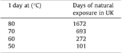
Three different aging processes were used during the tests immersion in hot water, freeze-thaw cycles and wet-dry cycles. Immersion in hot water is the most common accelerated aging process. This method consists of immersing GRC samples in tanks filled with hot water at a certain temperature and maintaining this temperature during a period of time. Equivalences between immersion periods and ordinary Portland cement mortar GRC age can be seen in Table 2 for United Kingdom climate and differ-ent temperatures [24].
Aging factors for OPC GRC shown in Table 2 were based on the Arrhenius type relation. Some authors have pointed out that these equivalences could not be valid for GRC manufactured with cement mortar with additions such as metakaolin or acrylic resins [25]. New equivalences for different matrices compositions were estab-lished. In Table 3 the modified equivalences between 1 day of immersion in water at 50 °C and the natural exposure time in the United Kingdom can be seen. However, the values found in this
Table 1
GRC formulations.
Cement (kg) Sand (kg)
Control 50 50 Metakaolin 50 50 Silica fume 10% 50 50 Silica fume 20% 50 50
Table 2
Accelerated aging equivalences for OPC. 1 day at(°C)
80 70 60 50
Days of natural exposure in UK 1672
693 272 101
Table 3
Acceleration factors for 1 day of immersion in water at 50 °C.
Days of natural exposure in UK Ordinary Portland cement GRC 101
OPC + 20% metakaolin 18 OPC + 5% acrylic polymer 18
research were only valid for the formulations used and no predic-tions were made for GRC manufactured with different addipredic-tions or different proportions of the same additions. Therefore, no predic-tions could be made for OPC with silica fume.
In this study GRC samples were immersed in hot water during 40, 80 and 120 days. Freeze-thaw cycles were performed in sam-ples stored in a climatic chamber. The temperature ranged from 20 °C to - 2 0 °C. The temperature profile of the cycle used in the climatic chamber can be seen in Fig. 1. GRC samples were sub-jected to 25 and 50 freeze-thaw cycles.
Finally, GRC samples were subjected to wet-dry cycles. GRC samples were stored immersed in water at 20 °C for 24 h and after-wards dried in a climatic chamber at 70 °C during 24 h. This pro-cess was carried out in GRC samples 50, 100 and 200 times.
As part of wider research, different test boards are at present being subjected to the Madrid climate in order to compare acceler-ated aging methods and natural weathering when they reached the adequate age.
2.3. Tensile tests
Tests were performed on 300 x 50 mm samples both of young GRC and aged GRC after immersion in water at 50 °C for 40, 80 and 120 days. This temperature was chosen in accordance with the results obtained by previous authors [25] and to avoid possible damage of chemical reactions between glass fibers and the cement mortar matrix during the accelerated aging process.
Tensile tests were carried out in a universal testing machine, equipped with a 25 kN load cell, with samples being held by using a pair of mechanical jaws. The strain of the samples while testing was obtained by using two extensometers, facing one another, placed in the center of the sides of the samples. The distance be-tween the blades of the extensometers was modified using exten-sions, in order to increase the possibility of recording the strain of the fracture area during the tensile tests. When the fracture was lo-cated in this zone, strain data that describes how the fracture developed was then recorded. Tests were performed using position
Water (kg) Plasticizer (kg) Addition (kg)
20 0.5
Freeze-thaw cycle Ductility vs. aging period
20
10 O
£
p y o
¡5 u.
V
K- 1 0
-20
4 6 8
Time (hours)
Fig. 1. Freeze-thaw cycle.
10 12
0.012
0.01
0.008
2 0,006 35
0.004
0.002
- • - O P C
- 8 - OPC • 10% siltca fume - a - OPC * 20% silica fume —*— OPC + 10% melakaolin
V\
1 = 7~ **
20 40 60 80
Immersion (days)
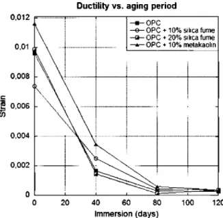
Fig. 3. Ductility vs. aging period.
100 120
control and the displacement of the jaws limited at a speed of 1 mm/min. Tensile tests were carried out up to the point of full fracture of the sample. Detailed test results can be found in Ref. [26]. Figs. 2 and 3 summarize the evolution with aging time of maximum tensile stress and strain respectively. Each point in Figs. 2 and 3 is the mean value of at least five test results where com-plete fracture occurred in the middle third of the sample. Ductility has been defined as the strain of the peak load previous of the total fracture process both in tensile and bending tests.
While performing tensile tests a large amount of samples were fractured either out of the middle third of the sample or inside the contact area between the mechanical jaws and the tested sample. Test results were discarded when the facture zone was not in the middle third of the sample. Due to this fact it was decided to carry out four point bending tests because it is a more stable test and less material was spoiled.
Tensile strength vs. aging period
0. 4
in
0> 3
^ L ^ ¡
^ r
^
^ s ,
- • - O P C
^ a - O P - * - O P
Z+ 10% s
; * 20% s
Z * 10% rr
lica fume lica fume etakaohn
20 40 60 80 100 120
Immersion (days)
Fig. 2. Tensile strength vs. aging period.
2.4. Four point bending tests
Four point bending tests were carried out on 225 x 50 GRC samples, both on young GRC samples and subjected to 25 and 50 freeze-thaw cycles. These tests were performed following the rec-ommendations of the European test method EN 1170 [27]. All four GRC formulations (OPC GRC, OPC GRC+10% silica fume, OPC GRC + 20% silica fume, OPC GRC + 10% metakaolin), were used in four point bending tests. Such four point bending tests were also carried out in OPC GRC, subjected to 50, 100 and 200 wet and dry cycles. Tests were performed in at least eight samples of each combination of formulation, number of cycles and aging method.
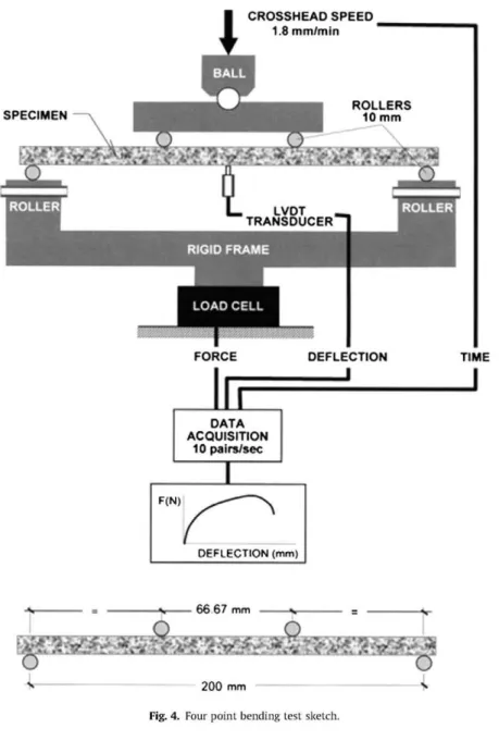
Bending tests were carried out in a universal testing machine, equipped with a 25 kN load cell. Samples were supported by two 10 mm diameter steel rollers placed at 12.5 mm from the samples' edges. These rollers were placed at the top of a rigid frame sup-ported by the load cell.
Samples were loaded using a specially designed steel loading head fixed to the testing machine crosshead. This loading head al-lowed rotations in the vertical and horizontal axis. Using this ele-ment no damage localization occurred during the tests, even though significant differences in sample thickness were observed. Crosshead movement was transferred to the sample by two 10 mm diameter steel rollers placed at 66.67 mm from the sup-porting rollers.
To record the deflection data, a linear variable differential trans-former (LVDT) was used. Its working distance range was ±5 mm and it was able to detect up to 1 urn displacements. Load, deflec-tion and time were recorded using a data acquisideflec-tion system that registered 10 pairs per second. Tests were performed using posi-tion control and crosshead speed of 1.8 mm/min. A sketch of the four point bending tests can be seen in Fig. 4.
Tests were carried out up to specimen complete failure or until LVDT maximum displacement was reached. In any case, when this happened the maximum load of the sample had been previously reached and therefore the specimen was already unloading.
CROSSHEAD SPEED 1.8 m m / m t n
SPECIMEN
FORCE DEFLECTION TIME
DATA ACQUISITION
10 pairs/sec
F(N)
DEFLECTION (mm|
-s 66 67 mm
'"ifctfr *S"C
200 mm
Fig. 4. Four point bending test sketch.
Fig. 5. Four point bending test.
To derive stress-strain curves from test data, the European test method EN 1170 was followed. Stress and strain were obtained using these relationships:
108 FL
'^bcf
108 Ad
(1)
(2)
where F is load, L stands for the distance between the support-ing rollers, b is the sample width, d is the sample thickness and A is the deflection at midspan.
O 0,002 0,004 0,006 0,008 0,01 Strain
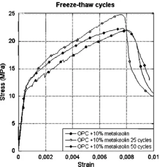
Fig. 6. OPC GRC with 10% metakaolin four point bending test stress-strain curve.
and the lower half is being subjected to tensile stresses. GRC tensile strength is considerably lower than GRC compressive strength [4] and therefore damage and microcracks appear in the lower half of the samples, with it being more precise in the lower side of the sample. Microcracks are created in the weakest zone of cement mortar matrix, within the mid-third where stresses are higher, be-cause cement mortar has lower tensile strength than glass fibers. Microcracks grow and this growing process stops when the tip of the crack reaches a glass fiber and the fiber bridges both sides of the crack. During the microcrack growing process, GRC is not able to withstand higher loads, shown as a drop in the stress-strain curve. However, when a glass fiber is bridging the two sides of the crack the microcrack growing process stops and the stress that were bore by the matrix are transferred to the glass fibers. Due to its higher mechanical strength, GRC is capable of bearing higher loads without total failure of the material. This effect is reflected in the stress-strain curve as a rise. This increase in the load with-stood by the GRC samples finishes when the tensile strength of the cement mortar matrix is reached elsewhere in the sample, and the process described previously begins. In the bridged microcracks the fibers are pulled out while the load increases and the growing and creation of new microcracks continues.
This course carries on until the stress in some part of the GRC sample is high enough to produce a visible macrocrack, propagated from the weakest microcrack previously created in the specimen. The point where the GRC begins to collapse and the load starts to decrease is called the moment of rupture point (MOR). During this process no damage was observed in the part of the sample being compressed.
Fig. 6 shows the behavior of OPC three samples of GRC with 10% of metakaolin addition both young and aged after 25 and 50 freeze-thaw cycles. Results shown in Fig. 9 are the mean values of the eight samples tested. In these stress-strain curves, all the characteristics previously described can be clearly observed. Stress-strain curves for all GRC formulations were similar to the ones showed in Fig. 6 and can be easily found in literature [4,18]. Similar results were obtained in OPC GRC after wet and dry cycles.
3. Discussion
Tensile test results have been previously summarized in Figs. 2 and 3. Each point in Figs. 2 and 3 is the mean value of at least five
Table 4
Real age after immersion in hot water.
Immersion time (days)
40 80 120
Real OPC GRC 13.2 26.3 39.5
age after immersion in hot water at 50 °C (years) OPC GRC +
MTK 2.0 3.9 5.9
10% OPC OPC
GRC + 10%SF GRC + 20%SF 2.0 2.0 3.9 3.9 5.9 5.9
test results where complete fracture occurred in the middle third of the sample. In these figures different GRC formulations behavior have been compared and its evolution with time has been plotted. If acceleration factors obtained in previous studies [25] are applied to the immersion periods previously cited (40, 80 and 120 days) the "real" GRC age is obtained. Due to the lack of data about the acceleration factors concerning OPC GRC with silica fume addition, and in order to remain within a reasonable safety margin, the accelerations factor of GRC with 20% of metakaolin addition has been applied. Those results can be seen in Table 4.
According to the data showed in Table 4, Figs. 2 and 3 have been replotted in Figs. 7 and 8, taking into account GRC "real" age. Fig. 7 shows how GRC tensile strength evolves with time. Curves in Fig. 7 show that, according to the acceleration factors used, tensile strength of OPC GRC with additions should deteriorate consider-ably faster than normal OPC matrix. Moreover, this tendency is also confirmed when comparing strain at MOR. The evolution of maxi-mum strain values of modified formulations of ordinary GRC are notoriously lower than those of OPC GRC at the same age.
Not all these results agree with those found in the literature, where OPC GRC with metakaolin addition always retained higher tensile strength and ductility [18,28]. Test results performed in GRC+10% metakaolin samples are considerably different than those found in the literature [29]. In such other studies, the behav-ior of artificially aged (immersion in hot water at 50°) GRC with at least 20% of metakaolin addition proved to retain a higher amount of ductility when the total failure of the sample took place. In addi-tion, the failure stress of the samples was similar to those obtained in samples that were not artificially aged. As can be seen in Figs. 2 and 3 both the ductility and flexural strength of the samples de-creased drastically after the aging period. The difference in
Tensile strength vs. equivalent age
"
- • - O P C- e - O P C + 10% silica fume - a - OPC + 20% silica fume —*— OPC + 10% metakaolin
0 5 10 15 20 25 30 35 40 Age (years)
Ductility vs. equivalent age Ductility vs. freeze-thaw cycles 0.012 F
0,01
0.008
| 0.006
0.004
0.002
-• - • - O P C
- e - OPC + 10% silica fume - a - OPC + 20% silica fume —*— OPC + 10% metakaolin
^»
0 5 10 15 20 25 30 35 40
Age (years)
Fig. 8. Ductility vs. equivalent age.
behavior between these two studies can be explained because dif-ferent amounts of metakaolin were used in these test campaigns. In the tests carried out by Brandt and Glinicki [29] at least 20% of cement was substituted by metakaolin or other pozzolanic com-pounds. However, in this study the amounts of pozzolanic products used were referred to the total amount of cement. Therefore GRC manufactured with an addition of metakaolin equal to 10% of the total cement weight is equal to having a substitution of 9.1% of the cement weight for metakaolin. There is a clear difference be-tween the quantities of pozzolanic products used in both studies and this could be the reason for the behavior differences found.
Figs. 9 and 10 were obtained by summarizing the results ob-tained in the four point bending tests. According to Fig. 9, OPC GRC shows a continuous decrease of its bending strength due to the freeze-thaw cycles. In addition, Fig. 10 shows that this de-crease of bending strength is directly related to a loss of ductility at MOR. Ductility decreasing rates in OPC GRC are higher in the first 25 freeze-thaw cycles where GRC loses around 65% of its strain capacity. Not only does this loss stop in the next 25 cycles, it also continues until losing 80% of GRC strain capacity after 50 cy-cles. Both Figs. 9 and 10 show how OPC GRC deteriorates with freeze-thaw cycles becoming a more brittle material with less bending strength.
However, GRC formulations with silica fume have slight changes in bending strength. Freeze-thaw cycles seem to affect lightly GRC modified with silica fume. This lack of damage is con-firmed when comparing maximum strain as illustrated in Fig. 10. The reduction of ductility after the 50 cycles is limited for the two formulations with silica fume studied. OPC with 20% of silica fume preserves almost all its ductility and only a minor loss of 10% was recorded during the tests. OPC with 10% silica fume lost 25% of its strain capacity after 50 freeze-thaw cycles.
Similarly, OPC GRC produced with 10% of metakaolin addition show after 50 cycles that its bending strength has remained in the similar values than those showed before artificial aging. Even after 25 cycles there is a rise in bending strength of 30% that is sub-sequently reduced to the original values after the next 25 cycles. In addition, ductility values for OPC GRC with 10% of metakaolin addi-tion remain nearly constant during the aging process. The evolu-tion of bending strength and ductility with freeze-thaw cycles demonstrate that OPC GRC produced with 10% of metakaolin
25
20
£ 1 5 2
10
,
—i- • - O P C
- e - OPC * 10% silica fume - a - OPC • 20% smca fume --*— OPC • 10% metakaotn
0.012
0,01
0.008
{«.
0.004
0.002
10 20 30 40 freeze-thaw cycles
Fig. 9. Bending vs. freeze-thaw period.
Ductility vs. freeze-thaw cycles 50
\
H^
v
^
OPCOPC+ 10% silica fume OPC + 20% silica fume OPC + 10%metakao!m
^=1K.
<
10 20 30 40
freeze-thaw cycles
Fig. 10. Ductility vs. freeze-thaw period.
50
50 100 150 WET-DRY CYCLES
addition is capable of withstanding severe weather conditions without suffering any damage.
Therefore, four point bending tests after freeze-thaw cycles showed results that were consistent with those found in the liter-ature [18,27], even though they were obtained through a different aging method. Similarly, as can be observed in Fig. 11, wet-dry cy-cles also have a harmful effect in plain GRC behavior. Bending strength and ductility decrease continuously with wet-dry cycles. Values obtained after 200 cycles were similar to those obtained after 50 freeze-thaw cycles.
4. Conclusions
The usual method of accelerated aging of GRC by immersion in hot water was revealed as an unreliable method for modern for-mulations including additives such as silica fume or metakaolin, due to the lack of repetitive results, especially in GRC manufac-tured with small amounts of metakaolin (around 10% of cement substitution). Immersion in hot water seems to deteriorate GRC formulations with additions that have proved to preserve its mechanical properties over the long term. Acceleration factors found in the literature should be questioned when dealing when GRC manufactured with modified matrices.
Even though freeze-thaw cycles do not reproduce the real environmental conditions to which GRC is subjected, freeze-thaw cycles were capable of causing damage on OPC GRC. Modified OPC GRC showed very little sensitivity to freeze-thaw cycles. This data was consistent with the literature. Wet-dry cycles have a harmful effect in OPC GRC and also simulate actual weather conditions.
An alternative aging method, combining freeze-thaw cycles and dry cycles or a simpler aging method consisting only in wet-dry cycles seem to be the most accurate simulation of weather conditions that produce a noticeable change on GRC mechanical properties. Future work should be carried out following this ratio-nale to find a correlation between real weather and the proposed aging method.
Acknowledgments
The authors wish to express their gratitude to SIKA, to CICYT for financial support Project BIA 2004-07336 and CONSOLIDER INGE-NIO 2010.
References
[1] Young J. In: Designing with GRC. London: Architectural Press; 1978. ¡2] True G. In: GRC production and uses. London: Palladian Publications Ltd.;
1986.
[3] Glass fibre reinforced cement association: international survey of GRC, use and development 1978/87, GRCA, Newport; 1989
[4] Majumdar AJ, Laws V. In: Glass fibre reinforced cement. Oxford: BSP Professional Books; 1991.
[5] Stain C. Architectural criteria for glassfibre reinforced concrete. In: GRC proceedings of the 10th international GRCA congress, Strassbourg; October 1995.
[6] Muller D, Morrison IJ. Recent developments in glassfibre reinforcement. In: Rossi P, Precast Chanvillard G, editors. Fibre reinforced concretes (FRC) BEFIP2000. RILEM Pub.; 2000.
[7] Cian D, della Bella B. GRC Precast elements for extra-light self-supportings floors in offices and residential buildings. In: GRC proceedings of the 12th international GRCA congress, Barcelona; October 2003.
[8] della Bella M, Cian D. Extra light GRC sandwich elements for roofing in industrial buildings. In: GRC proceedings of the 12th international GRCA congress, Barcelona; October 2003.
[9] Ferreira JC, Branco FA. Structural application of GRC in telecommunication towers. Constr Build Mater 2007;21:19-28.
10] Bentur A, Mindess S. In: Fibre reinforced cementitious composites. New York: Elsevier Science Pub.; 1990.
11 ] Bartos PJM, Zhu W. Effect of microsilica and acrylic polymer treatment on the ageing of GRC. Cem Concr Compos 1996;18:31-9.
12] Mobasher B, Shah S. Test parameters for evaluating toughness of glass-fiber reinforced concrete panels. ACI Mater J 1989;86:448-58.
13] Shah SP, Ludirdja D, Daniel JI, Mobasher B. Toughness-durability of glass fiber reinforced concrete systems. ACI Mater J 1988;85:352-60.
14] OJan X, Shen B, Mu B, Li Z. Enhancement of aging resistance of glass fiber reinforced cement. Mater Struct 2003;36:323-9.
15] Peled A, Jones J, Shah SP. Effect of matrix modification on durability of glass fiber reinforced cement composites. Mater Struct 2005;38:163-71. 16] Purnell P, Short NR Page CL A static fatigue model for the durability of glass
fiber reinforced cement. J Mater Sci 2001;36:5385-90.
17] Liang W, Cheng J, Hu Y, y Luo H. Improved properties of GRC composites using commercial e-glass fibers with new coatings. Mater Res Bull 2002;37(4):641-6.
18] Marikunte S, Aldea C, Shah SP. Durability of glass fiber reinforced cement composites. Adv Cem Mater 1997;5:100-8.
19] Ball H, Wackers M. Long term durability of naturally aged GFRC containing Forton polymer. In: Clarke N, Ferry R editors. Proceedings of the 13th congress of the international glassfiber reinforced concrete association, Dublin, Ireland; 2001. p. 83-95.
20] Purnell P. Interpretation of climatic temperature variations for accelerated ageing models. J Mater Sci 2004;39:113-8.
21] Peaston C, y Cather W. Properties and life prediction of cem-fil GRC cladding after more than 15 years of service. In: GRC proceedings 2003, Barcelona, España; 2003.
22] Takeuchi Y, Nishibori S. y Kobayashi M. Freeze-thaw resistance of premix GRC. In: GRC proceedings 2003, Barcelona, Spain; 2003.
23] Gilbert GT. GRC standing the test of time. In: GRC proceedings 2003, Barcelona, Spain; 2003.
24] Litherland KL, Oakley DR, Proctor BA. The use of accelerated ageing procedures to predict the long term strength of GRC composites. Cem Concr Res 1981;11:455-66.
25] Purnell P, Beddows J. Durability and simulating ageing of new matrix glass fiber reinforced cement. Cem Concr Compos 2005;27:875-84.
26] Enfedaque A, Cendón D, Calvez F, Sánchez-Gálvez V. Analysis of glass fiber reinforced cement (GRC) fracture surfaces. Constr Build Mater 2010;24:1302-8.
27] European committee for standardization (1998) EN 1170 parts 1-7 precast concrete products: test methods for glass-fiber reinforced cement, Bruxelles. 28] Purnell P, Short NR Page CL, Majumdar AJ, Walton PL Accelerated ageing
characteristics of glass-fibre reinforced cement made with new cementitious matrices. Composites part A: applied science and manufacturing 1999;30(9):1073-80.
[29] Brandt AM, Glinicki MA. Effects of pozzolanic additives on long-term flexural toughness of HPGFRC. In: Naaman AE, Reinhardt HW, editors. Fourth international workshop on high performance fiber reinforced cement composites, (HPFRCC 4). Bagneux, France: RILEM Publications; 2003. p.