STREM 1 based sepsis detection with centrifugal microfluidics incorporating active valves and image analysis
65
0
0
Texto completo
(2) Declaration of Authorship. I, Jonathan Medrano Danes, declare that this thesis titled, “s-TREM1 based Sepsis Detection with Centrifugal Microfluidics by Active Valves Means and Image Processing” and the work presented in it are my own. I confirm that:. . . This work was done wholly or mainly while in candidature for a research degree at this University. Where any part of this thesis has previously been submitted for a degree or any other qualification at this University or any other institution, this has been clearly stated. Where I have consulted the published work of others, this is always clearly attributed. Where I have quoted form the work of others, the source is always given. With the exception of such quotations, this thesis is entirely my own work. I have acknowledged all main sources of help. Where the thesis is bases on work done by myself jointly with others, I have made clear exactly what was done by others and what I have contributed myself.. Jonathan Medrano Danés Monterrey Nuevo León, December, 2017. @2017 by Jonathan Medrano Danés All rights reserved ii.
(3) Instituto Tecnológico y de Estudios Superiores de Monterrey Campus Monterrey School of Engineering and Sciences The committee members, hereby, certify that have read the dissertation presented by Jonathan Medrano Danés and that it is fully adequate in scope and quality as a partial requirement for the degree of Master of Science in Electronic Systems.. _____________________________ Sergio Omar Martínez Chapa, PhD Tecnológico de Monterrey School of Engineering and Sciences Principal Advisor. ______________________________ Mohammad Mahdi Aeinehvand, PhD Tecnológico de Monterrey School of Engineering and Sciences Co-advisor. ______________________________ Graciano Dieck Assad, PhD Tecnológico de Monterrey School of Engineering and Sciences Committee Member. ______________________________ Rute Fabiana Martins Fernandes, PhD Tecnológico de Monterrey School of Engineering and Sciences Committee Member. ____________________________. iii.
(4) Dedication I would like dedicate this work to my Lord Jesus Christ my all; to my dad and mom Luis and Zzori my greatest living examples, to my brother and sister Adiel and Carolina for their love and pray; to my cousins Emilio and Vanesa for their encouragement and friendship; and to Berenice Soto a person who gave me priceless support.. iv.
(5) Acknowledgments. I would like to express my sincere gratitude to all those who directly and indirectly made it possible for me to conclude this work, this stage of my academic formation. My deep gratitude to my advisor Dr. Sergio Omar Martínez for his trust, support and for taking care to provide me the resources to do and present this project. I want to say thank you to Dr. Mohammad Mahdi Aeinehvand for his guidance all along the development of this work, his encouragement, instruction and true friendship. To M.C Martín Francisco Jiménez Moreno a dear friend, for his advice, partnership and development of tools essentials to fulfill this project. To Dr. Samira Hosseini for her patience at the beginning of this project, her help with basic understanding of ELISA protocols and encouragement. To Rute Fernandes, an incredible person, for her aid in reagents handling, advice and guidance in redaction of this work; To BioTech Center Staff Members for their training and disposal of facilities to perform essential experiments. Special thanks to my master degree professors, including master degree program director Dr. Gabriel Campuzano, knowledge is worth more than gold refined seven times, and I am a big debtor to all of you. Thank you for your patience, time and faith in me. I am grateful to CONACYT for giving me the support for living (CVU 636295) and make me feel that the work I perform as a postgraduate student is appreciated. I’m very grateful to ITESM for opening its doors, for giving me the possibility to follow the path for my professional development and, above all, for giving me the opportunity to meet and interact with all these great people. This thesis work has been supported by the CONACYT grant no. 267726: “Development of a CD-Based Microfluidic Platform with Electrochemical and Optical Sensing for Medical Diagnostics and Environmental Monitoring”, of the 2015 CONACYT-DAAD Program.. v.
(6) s-TREM1 based Sepsis Detection with Centrifugal Microfluidics by Active Valves Means and Image Processing Jonathan Medrano Danés. Abstract Sepsis is the main cause of neonate death in hospitals. According to WHO, around one million neonatal deaths are caused each year because of sepsis. Rapid and early sepsis detection, are necessary for effective treatment of the patients to reduce the mortality rate, however this is still a big challenge, especially in low income countries with a poor healthcare system. Recently, soluble triggering receptor expressed on myeloid cells-1 (sTREM-1) biomarker has showed to be an accurate indicator for sepsis detection in neonates. When compared to conventional tests that take several days up to a week, sTREM-1 immunoassay is a faster approach for sepsis detection as it can be performed in five hours. However, the sTREM-1 immunoassay must be performed in a clinic laboratory by specialized staff and require several expensive and bulky equipment. One way to enable the sTREM-1 immunoassay outside specialized labs or at point-of-care (POC) is the integration of the complex assay into a centrifugal microfluidic platform. The disc-shaped microfluidic platform also known as lab-on-disc (LoD), employs centrifugal force from spinning of the disc to manipulate samples and reagents. The centrifugal force that exist everywhere on the disc prevents the need for several expensive syringe pumps. However, it makes simultaneous control over the retention and flow of several reagents/samples on a LoD challenging. To overcome this problem and automate sTREM-1 immunoassay for POC settings, this document presents the development of a new sacrificial polyethylene and a novel reversible valving mechanism on LoD. Based on the two valving mechanisms, a sTREM-1 immunoassay LoD is developed for sepsis detection. Integrating a series of sacrificial valves in the disc allowed for storage of reagents in the disc and their controlled release to a reaction chamber. The reversible valve, was used for the retention of each reagent in the detection chamber during incubation periods, and then transferring it to a waste chamber. A portable spinning system was developed to run the assay by microfluidic disc at POC. The successful automation of sTREM1 immunoassay on the microfluidic disc can provide a significant contribution in the reduction of complexity of the resources needed for sepsis detection at POC settings, particularly in remote areas.. vi.
(7) Content Index List of figures ..................................................................................................................................... 8 List of Tables ................................................................................................................................... 10 CHAPTER 1. INTRODUCTION. ...................................................................................... 11 CHAPTER 2. BACKGROUND ........................................................................................ 15 2.1 Lab-on-a-Disc. ........................................................................................................ 15 2.2 Valving in Centrifugal Microfluidics. ........................................................................ 18 2.3 Disc Materials and Fabrication Techniques. ........................................................... 26 CHAPTER 3. STATE OF ART ......................................................................................... 29 3.1 Microballoon mixers on centrifugal microfluidic platforms ......................... 29 3.2 Plasma separation and cell sorting on CD platform. ............................................... 31 3.3 A fully integrated multiplexed immunoassay on a disc. ........................................... 32 3.4 Centrifugal microfluidic ELISA imprecision analysis. ............................................... 33 3.5 Fully automated immunoassay from whole blood on a disc. ................................... 34 3.6 Array-based capture on a centrifugal microfluidic platform. .................................... 35 CHAPTER 4. MATERIALS AND METHODS................................................................... 37 4.1 Design .................................................................................................................... 38 4.2 Fabrication ............................................................................................................. 41 4.3 Experimental Setup. ............................................................................................... 46 4.4 Demonstrative ELISA ............................................................................................. 47 4.5 sTREM-1 LoD ELISA.............................................................................................. 53 4.6 Reading .................................................................................................................. 56 CHAPTER 5. sTREM-1 LOD ELISA RESULTS .............................................................. 57 5.1 Demonstrative ELISA results. ................................................................................. 57 5.2 Optimization Process Discussion............................................................................ 59 CHAPTER 6. CONCLUSIONS AND FUTURE WORK. ................................................... 62 6.1 Conclusions............................................................................................................ 62 6.2 Future work. ........................................................................................................... 62 References ...................................................................................................................................... 63. 7.
(8) List of figures Figure 1. SIRS and sepsis stages. .................................................................................................... 11 Figure 2. Areas with high mortality index in neonates caused by sepsis. ......................................... 12 Figure 3. Sandwich ELISA description chart. .................................................................................... 13 Figure 4. Resources needed for ELISA.. .......................................................................................... 14 Figure 5. Schematic of forces present on a rotating platform.. ......................................................... 17 Figure 6. Steps to use compressed air to pump liquid back to disc center. ...................................... 18 Figure 7. Illustration of the capillary valve function.. ......................................................................... 19 Figure 8. Detailed example of hydrophobic valve design.. ............................................................... 19 Figure 9. Principle of executing reagent adding sequences by the use of single or double syphon valves and by controlling rotation speed. .......................................................................................... 20 Figure 10. Common passive valves for LoC. .................................................................................... 21 Figure 11. Description of compressed air valve actuation and composition. .................................... 21 Figure 12. Design for using pneumatic valves for aliquoting liquid volumes . .................................. 22 Figure 13. Reversible PDMS passive valve.. .................................................................................... 22 Figure 14. Scheme of sacrificial ferrowax valve. ............................................................................... 23 Figure 15. Sacrificial thin plastic valve .............................................................................................. 24 Figure 16. Magnetically actuated valve. ............................................................................................ 24 Figure 17. Magnetically actuate valve design proposed by Aeinehvand, M. M et al.. ..................... 25 Figure 18. RTPV working principle scheme. ..................................................................................... 26 Figure 19. ELISA design developed by UCA cutted by CNC machine. ............................................ 27 Figure 20. CD micromachining using CNC. ...................................................................................... 28 Figure 21.CNC engraver cutting plastic. ........................................................................................... 28 Figure 22. CD assembly procedure .................................................................................................. 29 Figure 23. A comparison between the biosensing enhancement of 3.54p.f.u/mlNS1in CD-like well plates using microballoon and stopped-flow methods. ..................................................................... 30 Figure 24. Microspheres developed to enhance dengue detection on CD platform microfluidic device. ............................................................................................................................................... 30 Figure 25. Performance of the microspheres in DV detection.. ........................................................ 31 Figure 26. Plasma separation and collecting process developed by UCA staff. .............................. 31 Figure 27 Cell quantification using CD microfluidics. ........................................................................ 32 Figure 28. LoD ELISA for dengue using ferrowax sacrificial valves and microbeads for mixing . .... 32 Figure 29. Microfluidic CD design for 104 fluorescence based sandwich immunoassays. .............. 33 Figure 30. Zoomed view of design of four sets of sandwich immunoassays . .................................. 33 Figure 31. Layout of centrifugal device used for fully automated direct ELISA implementation for HBV detection.................................................................................................................................... 34 Figure 32. Calibration curves comparison between experiment direct ELISA (left) and manual direct ELISA from ELISA kit . ...................................................................................................................... 34 Figure 33. V shape structure for beads capturing.. ........................................................................... 35 Figure 34 Occupancy distribution for different cup sizes with 10-mm silica beads. .......................... 36 Figure 35. Methodology implemented for LoD development and optimization. ................................ 37 Figure 36. sTREM-1 ELISA LoD steps chart showing operation sequence and reduced incubation times. ................................................................................................................................................. 37 Figure 37. Polyethylene sacrificial valve.. ......................................................................................... 38 Figure 38. Active Reversible Push&hold Button Valve.. ................................................................... 38 Figure 39. LoD sTREM.1 ELISA CAD master design. ...................................................................... 40 Figure 40. Design analysis for residues search.. .............................................................................. 41 Figure 41. CAD master design layer decomposition for disc assembly. ........................................... 41 Figure 42. CNC cutting laser equipment used to fabricate PMMA CD layers. ................................. 42 Figure 43. CE6000 cutter plotter PSA cutting and preparation process. .......................................... 42 Figure 44. Test CD showing resulting fabricated sacrificial polyethylene valves.. ............................ 43. 8.
(9) Figure 45. Reversible push&hold button valve.. ................................................................................ 44 Figure 46. Assembly order of CD layers. .......................................................................................... 45 Figure 47. Centrifugal spinning platform used in experiments. ......................................................... 46 Figure 48. 300mW/400nm NEJE Laser Engraver. CD is place in engraver plate and polyethylene sacrificial valve can be actuated rapidly. ........................................................................................... 47 Figure 49. sTREM-1 LoD ELISA Layout. .......................................................................................... 47 Figure 50. Spinning profile to show shaking routine.. ....................................................................... 48 Figure 51. Sample sacrificial valve is actuated and CD is spun. ...................................................... 49 Figure 52. Once sample is in reaction chamber, incubation process is started to let antigen attach to first antibody already present in chamber. ........................................................................................ 49 Figure 53. Once incubation time is completed, reversible valve is opened and CD is spun to flush sample to waste chamber. ................................................................................................................ 49 Figure 54. Reversible valve is closed again, 1st wash step sacrificial valve is opened and CD is spun letting wash buffer fill reaction chamber. A small 30 seconds shake routine is executed to enhance removal of sample remaining. ............................................................................................ 50 Figure 55. Reversible valve is closed and CD is spun to flush washing buffer. ................................ 50 Figure 56. Wash step is performed 2 more times with adjacent washing buffer chambers.............. 51 Figure 57. With reversible valve closed, 2nd antibody sacrificial valve is opened, CD is spun first to propel reagent to reaction chamber and then putted in shaking routine for 1 hour incubation time. 51 Figure 58. Second antibody is flushed to waste chamber and three washing steps are performed as in revious steps. Last washing step is in right side of CD design, so in order to avoid Coriolis force to opose to liquid flow to reaction chamber the CD is spun counter-clock wise. This apply to all chambers in right side of design. ....................................................................................................... 52 Figure 59. By opening sacrificial valve and spinning CD CCW, streptavidin is deposited in reaction chamber and incubated in shaking sequence for 25 minutes. .......................................................... 52 Figure 60. Last 3 washing steps are perform. ................................................................................... 52 Figure 61. Substrate is placed in reaction chamber and incubated 5 minutes. ................................ 53 Figure 62. Stopping solution is added to substrate solution. ............................................................ 53 Figure 63. . Previous prototype of ELISA on a CD for sTREM-1 detection fabricated in clean conditions (Reversible valves not yet added). ................................................................................... 54 Figure 64. Clean CD for real ELISA test with loaded reagents, light protection for light sensitive reagents and identification labels. ..................................................................................................... 55 Figure 65. Photo analyzed with ImageJ software. Left: Selected area. Right: RGB histogram and mean data of selection. ..................................................................................................................... 56 Figure 66. Extraction of result liquid of sTREM-1 LoD ELISA to a conventional ELISA kit well-plate and placement in ELISA well-plate reader to measure absorbance rate at 400nm. ......................... 56 Figure 67. Incubation time optimization of sTREM-1 ELISA integrated in LOD system. Total immunoassay time was reduced from 5 hours to less than 3 hours. ................................................ 57 Figure 68. sTREM-1 LoD ELISA results. A) Positive labeled ELISA set result shows a clear yellow translated to presence of sTREM-1. B) Negative labeled ELISA set result is transparent with is translated to abscence of sTREM-1 biomarker. ................................................................................ 57 Figure 69. sTREM-1 LoD ELISA image analysis results. A) Positive result anaylis. B) Negative result analysis. C) Excel table that converts RGB values to KCMY used to measure yellow........... 58 Figure 70. sTREM-1 LoD ELISA well-plate reader results. Graph shows positive minus negative result of absorbance rate and compares it with conventional ELISA numeral. ................................. 59 Figure 71. A) Ferrowax mix procedure; B) Electrical circuit for heat addition to micropipette tip ..... 60 Figure 72. Ferrowax valves test CD results. Easy reproduction of sacrificial ferrowax valve was not possible. ............................................................................................................................................ 60 Figure 73. Reversible push&hold button valve bulk version. A) Topview. B) Sideview open. C) Sideview closed. ................................................................................................................................ 61. 9.
(10) List of Tables Table 1. Centrifuge systems features against other fluid propulsion means . .................................. 15 Table 2. LoC and LoD comparison.................................................................................................... 16. 10.
(11) CHAPTER 1. INTRODUCTION. Sepsis is a life-threating medical condition that occurs when the body has an overwhelming immunological response to a bacterial infection. The chemical substances released to fight the infection unchain a generalized inflammation which leads to blood clots formation and blood vessels filtering. This causes a poor blood stream which deprives the organs of nutrients and oxygen. Finally this may cause the failure of several organs which lead to a septic shock [1].. Figure 1. SIRS and sepsis stages [62].. Sepsis affects up to 8 neonates in each 1000 births and causes 1 million deaths per year, being one of the leading causes of neonate’s death. Because of symptoms are often subtle and nonspecific, its early detection is challenging .It is stated that at sepsis shock stage, each hour that passes increase death probability of affected individual to 8%, this reduction of detection time can reduce mortality rate of sepsis [3, 4]. When sepsis occur, the transmembrane glycoprotein TREM-1 triggers the inflammatory response and it has a soluble fraction denoted sTREM-1 which can be detected with a conventional ELISA kit. Arízaga Ballesteros et al. made a research to measure the accuracy of sepsis detection with sTREM-1 as indicator with a positive conclusion [2]. While conventional gold standard methods for sepsis detection can take up two days to be performed because they need slow procedures such as cell lysis to be performed, sTREM-1 ELISA can perform the detection in average 6 hours [6]. 11.
(12) Figure 2. Areas with high mortality index in neonates caused by sepsis [63].. Sandwich Enzyme-Linked Immunosorbent Assay (ELISA), a highly specific type of ELISA, is the gold standard in the detection and quantification of antigens between two layers of antibodies (i.e. capture and detection antibody). The antigen to be measured must contain at least two antigenic epitope capable of binding to antibody, since at least two antibodies act in the sandwich [5]. The advantage of Sandwich ELISA is that the sample does not have to be purified before analysis, and the assay can be very sensitive (up to 2 to 5 times more sensitive than direct or indirect ELISA) [5].. 12.
(13) Figure 3. Sandwich ELISA description chart [6].. ELISA kit and protocol was provided by Tec de Monterrey School of Medicine for this research work. The protocol of the test has the following steps [6]: 1. Add 100uL of sample or positive control to well-plate and incubate for 2 hours. 2. Remove sample from well-plate, add 300uL of washing buffer, shake well plate and throw. Repeat three times for a total of four washing steps. 3. Add 100uL of detection antibody working solution to well-plate and incubate for 2 hours. 4. Repeat washing procedure. 5. Add 100uL of Streptavidin-HRP Conjugate working solution and incubate for 45 minutes. Repeat washing procedure. 6. Add 100uL of substrate solution to each well plate and incubate for 10 minutes. 7. Add 100uL of stopping solution to each well. Determine the optical density of each well whiting 15 minutes using microplate reader set to 450nm. ELISA procedure needs to be performed by specialized staff in lab clean conditions and uses equipment such as orbital shaker, microplate washer and ELISA plate reader which are expensive and makes the test impossible at point of care.. 13.
(14) Figure 4. Resources needed for ELISA. A) ELISA well-plate reader. b) Microwell-plate washer. C) Orbital shaker. D) Specialize staff and Lab.. CD microfluidics-based immunoassays have been developed for various bioanalytical applications [58-60], most of them providing only the automation of some protocol steps. However, until now, no CD microfluidic has been develop to integrate sTREM-1 sandwich ELISA for sepsis detection. Therefore, the objective of this work is to develop a Lab-on-a-Disc (LoD) system for automated and rapid sepsis detection at point-of-care. This is made by integrating s-TREM1 immunoassay on a LoD system that uses sacrificial and reversible valves to diagnose sepsis, by sTREM-1 quantification. The sacrificial valves were laser activated using a 300mW/400nm laser engraver equipment controlled by software was used. In chapter two of the present document, theoretical background enclosing centrifugal microfluidics and valve techniques is presented for better understanding of the basic concepts here applied. Chapter three, presents state of the art of Lab-on-a-Disc implementation in immunoassay and clinic lab procedures as well as valving of interest in the development of sTREM-1 LoD prototype. Chapter four describes design, fabrication, experimentation and result reading procedures, while chapter five show experiments results and discuss the optimization process to reach final prototype was develop. Finally, chapter six exposes both result conclusions and potential future work to take further the presented project.. 14.
(15) CHAPTER 2. BACKGROUND 2.1 Lab-on-a-Disc. In the field of microfluidics several means for liquid pumping have been developed applying forces such as centrifugal, air pressure, acoustic and electrokinetic. These pumping methods have features that make them suitable for different applications. Table 1 describes the main advances and applications in the development of the microfluidic pumps [7, 8]. Table 1. Centrifuge systems features against other fluid propulsion means [7].. A centrifugal microfluidic device typically has the shape of a compact disc (CD) and uses pseudo forces that are induced from the spinning of the CD to manipulate liquids within its interconnected fluidic channels. Lab-on-a-disc (LoD) systems overcome several disadvantages of Lab-on-a-chip (LoC) systems, which use 15.
(16) external devices (e.g. expensive syringe pumps) to manipulate fluids through the channels. Table 2 compares the features of both LoD and LoC microfluidic devices. Table 2. LoC and LoD comparison [9].. As describe above, an induced centrifugal force from spinning a microfluidic CD using a simple spindle motor can propel liquids on the microfluidic platform. The liquid speed would be defined by [10]: 𝑈 = 𝐷ℎ2 𝜌𝜔2 𝑟̅ ∆𝑟/32𝜇𝐿 Where: 𝑈 : Average velocity of the liquid. 𝐷ℎ : Hydraulic diameter defined by 4𝐴/𝑃 𝐴 : Cross-sectional area 𝑃 : Wetted perimeter of the channel. 𝜌 : Density. 𝜔 : Angular velocity of the disc. 𝑟̅ : Average distance of the liquid in the channels to the center for the disc. ∆𝑟 : Radial extent of the fluid. 𝜇 : Viscosity. 𝐿 : Length of the liquid in the capillary channel. A simple motor generates several pseudo-forces on the platform: the centrifugal force, which acts as a liquid pump and generates a force gradient affecting fluids differently at varying radial positions; the Coriolis force, which allows for direction specific liquid-pumping control; and the Euler force, which can be used to create turbulence during mixing [10].. 16.
(17) Figure 5. Schematic of forces present on a rotating platform. Fω, centrifugal force; Fc, Euler force, which is perpendicular to the centrifugal force; and Fc, Coriolis force, which is perpendicular to the velocity [10].. This forces can be model using the following equations [10]. ⃗⃗⃗⃗ 𝐹𝜔 = 𝜌𝜔(𝜔 × 𝑟̅ ) ⃗⃗⃗ 𝐹𝑐 = −2𝜌𝜔 × 𝑈 𝑑𝜔 ⃗⃗⃗⃗ 𝐹𝐸 = −𝜌 × 𝑟̅ 𝑑𝑡 The importance of the understanding of these pseudo forces is significant in the design of a microfluidic disc. For instance, several designs of valves have been developed using just Coriolis force by taking advantage of some controlled variables such as speed or direction of rotation [11-13] Other concept involved in centrifugal microfluidics is the accumulation, venting or compression of air. Vent holes should be added to let air scape form a chamber in order for it to be filled with liquid. Compression of air can also be used to store energy of the centrifugal force and release it by decreasing centrifugal speed. By using this concept, liquid can be pumped not only outwards the center of the disc but also inwards which gives room to applications such as mixing or return liquid to a previous chamber, thus optimizing disc area usage [14].. 17.
(18) Figure 6. Illustration of the steps to use compressed air to pump liquid back to disc center. The geometry of the chamber leaves an area which the liquid cannot fill and stops the air to reach other chamber resulting in a compression of its volume. When disc is slowed down the pressure of air exceed centrifugal pressure thus pumping liquid back [14]. The first application of centrifugal microfluidics was in blood separation [15] but nowadays their main application is performing immunoassays. Nevertheless, LoD applications are growing and procedures such as digital chemical analysis and electrochemical whole blood analysis are being explored [16, 17].. 2.2 Valving in Centrifugal Microfluidics. Centrifugal force exists everywhere on the spinning platform and pushes all onboard liquids/reagents towards the outer rim of the CD. Therefore, microvalves are the main fluidic elements of a centrifugal microfluidic immunoassay as they provide robust control over the retention and release of reagents and samples on spinning CD. In another word, valves allow distribution of the reagents in the proper time and location. Valves that have been developed for lab on a cd applications can be divided in two classifications: Passive valves and active valves [7]. Passive valves rely on centrifugal force to restrict or allow liquid flow, and thus do not need the influence of any external device to the disc. Capillary passive valve. Its fundamental principle is based on a balance between capillary pressure (𝑃𝑠 ) and centrifugally- induced pressure (𝑃𝜔): liquid will not pass through a capillary valve when the centrifugal pressure is less than or equal to the capillary barrier pressure. Capillary pressure increases at the liquid–air interface when the cross section of a hydrophilic capillary expands abruptly [18].. 18.
(19) 4𝛾 𝑃𝜔 = 𝜌𝜔𝑐2 𝑟̅ ∆𝑟 > 𝑎 ( ) + 𝑏 = 𝑃𝑠 𝐷ℎ Where: 𝜔𝑐 = Critical burst frequency. 𝑎 = Scaling factor for non-spherical droplet shapes. 𝛾 = Surface tension. 𝑏 = pressure required to wet the chamber past the capillary valve. This kind of valve is the most used passive valve due to its simplicity and many different designs have been developed [19-26]. However, in order to accurately actuate this kind of valve, characterization of the involved fluid must be made and precise rotation control is necessary.. Figure 7. Illustration of the capillary valve function. [19].. Hydrophobic passive valve. Hydrophobic passive valves rely on either a sudden narrowing in a hydrophobic channel, or functionalized hydrophobic regions in microchannels to inhibit fluidic movement. In both cases, fluid can be forced past these valves when the rotational speed exceeds a certain critical value [27-33].. Figure 8. Detailed example of hydrophobic valve design. By externally wetting a paper control film the barrier dissolves and allow liquid flow [27].. 19.
(20) Syphon passive valve. Siphoning often relies on the priming of liquid into a siphon channel due to capillary action; therefore the siphon channel surface must be hydrophilic. When the disc is spinning at high speeds, centrifugal forces keep the meniscus front below the crest level of the siphon. When the rotating speed is reduced below a critical value, the channel is primed, and the siphon can transfer the liquid once the meniscus passes the crest point. The liquid flow stops if the liquid level is hydrostatically balanced or there is a discontinuity in the liquid column. Siphoning in centrifugal microfluidics provides a valving solution for the applications that require higher spin speeds as the first step of the operation [21, 22, 34]. Serial arrays of syphon valves have been proved to be a reliable way to add different reagents in a main chamber in certain order without stopping the CD but changing rotation speed [35].. Figure 9. Principle of executing reagent adding sequences by the use of single or double syphon valves and by controlling rotation speed [35].. 20.
(21) Figure 10. Common passive valves for LoC [36].. Compressed air valve On way to create a passive valve is using a trapped air as a physical barrier to prevent liquid entering the chamber. By having an initial chamber, a narrow channel and a final destination unvented chamber, when centrifuging the liquid fills the initial chamber and narrow channel but do not reach destination chamber because of the trapped air inside it. By increasing rotation speed, centrifugal pressure of liquid overwhelms compressed air counter-back pressure starting a drip of the liquid inside the destination chamber [37].. Figure 11. Description of compressed air valve actuation and composition [37].. Similar principle is using for aliquoting liquid volumes in a precise way with wide arrays of pneumatic valves for D. Mark et al [38].. 21.
(22) Figure 12. Design for using pneumatic valves for aliquoting liquid volumes [38].. PDMS seal valve. M. M. Aeinehvand et al. developed a reversible PDMS passive valve using a latex membrane stretched towards a PDSM semispherical seal. The stretched membrane pushes the seal down to a channel outlet preventing liquid to pass to a second channel. At certain burst speed the pressure made by liquid propelled by centrifugal force overwhelms opposite force of stretched membrane over pdsm seal, lifting the seal and allowing liquid to flow in radial direction to 2nd channel. When spinning speed is reduced, stretched membrane returns pdms seal to its closed position.. Figure 13. Reversible PDMS passive valve. Left: In normal conditions membrane press the seal towards outlet obstructing liquid flow. Right: At certain speed, centrifugal liquid pressure overwhelms membrane pressure to seal and valve is opened.. Active valves employ externally induced forces from additional/external equipment to control liquid flow on spinning CD [36]. This feature allows some active valves to be activated and deactivated multiple times allowing the reduction of designs,. 22.
(23) however this valves needs additional equipment that impacts in the cost and complexity of the centrifugal platform depending of the technology used. Sacrificial valve Laser irradiated ferrowax valve (LIFM) is the most common example of sacrificial valve which implements and obstruction in a channel between two chambers that restricts the liquid flow. This obstruction is composed by wax which is an hydrophobic material mixed with iron powder, the purpose of the mixture is to take advantage of the iron radiation absorbance property to enhance the heat absorption of the wax when exposed to laser which leads to a dramatically reduction of the minimum exposition time needed for melting [39-41].. Figure 14. Scheme of sacrificial ferrowax valve [33].. Recently, a thin plastic layer (0.125mm) with a series of carbon dot patterns is used as an alternative to ferrowax valves. The carbon dot absorbs laser radiation enough to melt the layer and unblock channel. This technique was used in the automation of microalgae lipid quantification [42].. 23.
(24) Figure 15. Thin plastic layer sacrificial valve. A) Disc design showing actuation valve sequence. B) Sideview showing valve function [42].. Magnetically actuated valve. Adding an electromagnet in the center of the CD centrifugal platform can enable the use of magnetic valves in disc design. Introducing ferromagnetic material spherical seals with radial orientation in the disc will produce a blocking in the target channel due to the centrifugal force acting with the mass of the seals avoiding liquid flow. When electromagnet is activated, if the magnetic field force is greater than centrifugal force the magnet and seals will act as a solenoid system unblocking the channels and letting the liquid to flow until magnetic field is removed [42].. Figure 16. (Left) Magnet in the center of the disc moves radial orientated ferromagnetic spherical seal when the magnetic force is greater than centrifugal force opening the valve. (Right) Magnetic field is not able to change azimuthal orientated ferromagnetic se al due to orientation [42].. 24.
(25) Figure 17. Magnetically actuate valve design proposed by Aeinehvand, M. M et al. where placement and displacement of blocking mechanism between channels is vertically oriented. A) Magnet is closed and keeps magnetic bead blocking two chambers connection. B) Magnet is retired and centrifugal liquid flow lifts magnetic bead and enters to second chamber [44].. Reversible Termo-Pneumatic Valve (RTPV) M. M. Aeinehvand et al. proposed a valve design that works using dilatation principle. Briefly, by having an air volume in a chamber that shares a flexible membrane wall with a narrow channel, this channel can be closed by heating the air volume in adjacent chamber, thus expanding the membrane and blocking liquid flow from one chamber to another. The process can be reversed by letting the air to cool and can be repeated indefinitely [44].. 25.
(26) Figure 18. RTPV working principle chart [44]. A) Latex membrane is shared by air chamber and microfluidic channel. B) By heating the air volume, dilatation expands membrane and obstructs channel. C) By letting the air to cool, membrane retracts and liquid can flow again in channel.. PDMS seal reversible valve. Acting counterwise to a RTPV, by using a PDMS seal stretched up with a flexible membrane towards an up going channel liquid flow can be stopped while the pressure applied by the PDMS seal remains greater than centrifugal pressure exerted by liquid. By increasing rotation speed, centrifugal pressure eventually overwhelms PDMS seal counter action pressure, thus because the membrane is flexible the seal yields back and allows liquid to flow [45].. 2.3 Disc Materials and Fabrication Techniques. Poly(methyl methacrylate) (PMMA), also known as acrylic or acrylic glass as well as by the trade names Plexiglas, Acrylate, Lucite, and Perspex among several others, is a transparent thermoplastic often used in sheet form as a lightweight or shatterresistant alternative to glass. The same material can be utilized as a casting resin, in inks and coatings, and has many other uses [46]. PMMA is an economical alternative to polycarbonate (PC) when extreme strength is not necessary. Additionally, PMMA does not contain the potentially harmful bisphenol-A subunits found in polycarbonate [47]. PMMA ignites at 460 °C and burns, forming carbon dioxide, water, carbon monoxide and low-molecular-weight compounds, including formaldehyde 26.
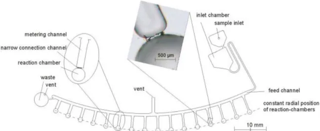
(27) PMMA transmits up to 92% of visible light at a 3 mm thickness, and gives a reflection of about 4% from each of its surfaces due to its refractive index (1.4905 at 589.3 nm). It filters ultraviolet (UV) light at wavelengths below about 300 (similar to ordinary window glass) [48]. Pressure sensitive adhesive (PSA) have been successfully used as adhesive material to assemble disc-shaped PMMA layers of CD microfluidic platforms. Furthermore, the computer numerical control (CNC) engraver machine has shown to be a reliable tool to draw the desire designs onto PMMA [49- 51]. An analysis of centrifugal force for CD ELISA was develop on 2010 by Aeinehvand, M. M. et al. using capillary valves using PMMA for disc manufacturing and was machined using CNC micromachining. The designed used seven reservoirs: waste, detection, serum, conjugate, washing solution, substrate and stopping solution [51].. Figure 19. Used ELISA design for UCA research party [8]. Waste (1), detection (2), serum (3), conjugate (4), washing solution (5), substrate (6) and stopping solution (7) [51].. 27.
(28) Figure 20. CD micromachining using CNC [51].. Other tool used for disc fabrication is the CNC laser engraver which prevents tool wear and tear from happening. By controlling the laser power appropriately, a welldefined patter can be made in a surface simply by exporting a CAD file with the desired designed to CNC software [51]. Using low power, laser engraver can also be used for sacrificial valve actuation.. Figure 21.CNC engraver cutting plastic [52].. More recently, 3D printers have been used to fabricate microfluidic discs, which adds the capability of implementing rounded channels cross sections and reducing the amount of layers needed for a specific application [53, 54]. Nevertheless, materials usable on 3D printing technology are mainly and PVA, which are not adequate to perform certain immunoassays. Furthermore, 3D printers that enable fabrication of small fluidic cartridges are very expensive and slow. Finally, photolithography has proven to be the most efficient method to develop centrifugal microfluidic prototypes [55] due to its capability of producing the smallest minimal dimension improving disc area optimization. Nonetheless, this technique requires many laboratory equipment and clean facilities, which makes it costly. With proper equipment and technician personal the reliable, quick and efficient production of prototypes can be achieved. 28.
(29) CHAPTER 3. STATE OF ART 3.1 Microballoon mixers on centrifugal microfluidic platforms Mohammad Mahdi Aeinehvand et al. developed a micromixer that operates by the expansion and contraction of a microballoons to produce a consistent periodical 3Dreciprocating flow. They established that microballoons reduced mixing time of 12μl liquids from 170 minutes to less than 23 seconds.. Figure 22. CD assembly procedure [50].. 29.
(30) Figure 23. A comparison between the biosensing enhancement of 3.54p.f.u/mlNS1in CD-like well plates using microballoon and stopped-flow methods [50].. Hosseini, S. et al. perform as well the integration of polystyrene microspheres and microballoon mixer in a microfluidic disk enabled highly sensitive and selective detection of dengue in a shorter time [46].. Figure 24. Microspheres developed to enhance dengue detection on CD platform microfluidic device [46].. 30.
(31) Figure 25. Performance of the microspheres in DV detection: (a) detection range analysis for the well plates and microfluidic disks with microspheres (20 mg of size 3 spheres) in comparison to the conventional ELISA (depicted results are original data along with their cut-off values) [46].. 3.2 Plasma separation and cell sorting on CD platform. As mentioned in the previously (chapter 1), plasma separation from raw blood can be achieved by using densities difference between blood components and centrifugal force. By the use of syphon structures, Amasia M. and Madou M. designed a quick an effective device to collect plasma that can be used to perform most of available immunoassays [56].. Figure 26. Plasma separation and collecting process developed by UCA staff [56].. Density difference between plasma and blood cells can be used for cell sorting by using a “Y” bifurcation of different diameters in such way that less dense plasma is 31.
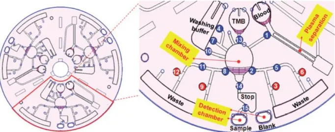
(32) the only one aloud to flow in the channel with the smallest diameter. Additionally plasma can be mixed using square patterned channel [57].. Figure 27. A) Bifurcation used to collect plasma. B) Square patterned channel of certain dimensions for plasma mixing [57].. 3.3 A fully integrated multiplexed immunoassay on a disc. Jiwoon Park et al. [58] developed a fully automated lab-on-a-disc for simultaneous detection of multiple protein biomarkers in samples such as whole blood or saliva. This for the simultaneous detection of C-reactive protein, cardiac troponin I, and Nterminal pro-B-type natriuretic peptide for the diagnosis of cardiovascular disease, based on the bead-based sandwich-type ELISA.. Figure 28. (A) A photograph shows the fabricated disc. (B) The schematic diagram of the multiplexed beadbased sandwich type ELISA is also shown. (C) The disc design shows the detailed microfluidic layout. The blue and the red circles with numbers are Normally Op en-Laser Irradiated Ferrowax Microvalves (NO)-LIFM and Normally Closed-Laser Irradiated Ferrowax Microvalves (NC)-LIFM, respectively. The number indicates the order of the valve operation. (D) A CCD image shows the main reaction chambers pre-loaded with PS beads [58].. 32.
(33) 3.4 Centrifugal microfluidic ELISA imprecision analysis. Honda, N. et al. designed a disc performing up to 104 sandwich type immunoassays with 200nL samples based in fluorescence reading. The results of the study showed a <20% imprecision percentage between samples. However protocols of ELISA kits typically used bigger samples (100uL) and fluorescent ELISA is less precise than absorbance ELISA. The experiment used hydrophobic valves and was not completely automated [59].. Figure 29. Twelve cm microfluidic CD design for 104 fluorescence based sandwich immunoassays [59].. Figure 30. Zoomed view of chambers and channels design of four sets of sandwich immunoassays [59].. 33.
(34) 3.5 Fully automated immunoassay from whole blood on a disc. A portable direct ELISA system was developed in a portable CD using laser irradiated ferrowax valves and microbeads in order to measure the concentrations of the antigen and antibody of Hepatitis B virus (HBV). All the necessary reagents were preloaded on the disc and processes of plasma separation and direct ELISA test were performed in the disc, including absorbance measurement. Results showed that calibration curves present a proportional pattern, when compared with conventional direct ELISA. However, reagent quantities and washing steps are not in agreement with conventional direct ELISA protocols [60].. Figure 31. Layout of centrifugal device used for fully automated direct ELISA implementation for HBV detection. Scheme show how three volumes can be obtained from a single washing buffer chamber [60].. Figure 32. Calibration curves comparison between experiment direct ELISA (left) and manual direct ELISA from ELISA kit (Genedia GreenCross Co.,Korea) (right) [60].. 34.
(35) 3.6 Array-based capture on a centrifugal microfluidic platform. Robert Burger et al. [61] successfully performed a technique for bead-based immunoassays to trap the beads and count them using sedimentation phenomenon enhance with centrifugal force. The impact of this techniques in the use of microspheres for reagents interaction enhancement is significant. The centrifugal microfluidic disc uses V shape structures to trap beads with a reported 100% efficiency and minimum instrumentation.. Figure 33. V shape structure for beads capturing. Using centrifugal force beads mix with a certain liquid, then when speed is reduced liquid ascends while beads remain in the bottom and a syphon valve empty the liquid away. The procedure can be repeated so microb eads can interact with different reagents in an immunoassay [61].. 35.
(36) Figure 34 Occupancy distribution for different cup sizes with 10-mm silicon beads (a–c) and 20-mm PS beads (d and e). a) 94% of all occupied cups contain a single bead. b) Increasing the active capturing area to 20 mm leads to a broader occupancy distribution. c) Occupancy distribution for cups with a 32-mm capturing. d) RC¼ 1, 99.7% single occupancy and only 5% of all cups empty. e) RC¼ 1.6, 48.8% are occupied by a single bead and 27% contain 2 beads [61].. 36.
(37) CHAPTER 4. MATERIALS AND METHODS In order to develop a full functional and optimized prototype, the methodology showed in figure 35 was followed.. Figure 35. Methodology implemented for LoD development and optimization.. sTREM1-1 ELISA kit datasheet shows the steps and incubation times needed to perform the immunoassay[], however by using a shaking routine with motor mixing is added and the incubation times were reduced to half giving the protocol expressed in figure 36.. Figure 36. sTREM-1 ELISA LoD steps chart showing operation sequence and reduced incubation times.. 37.
(38) 4.1 Design Incubation of reagents is performed in reaction chamber containing ELISA wellplate which is treated by ELISA kit manufacturer to already contain first capture antibody. In order to control reagents deposition which will be stored in chambers of our microfluidic device polyethylene sacrificial valve concept was developed.. Figure 37. Polyethylene sacrificial valve. Left: Thin polyethylene layer interpose between two channels at different height levels sharing a common area colored with black color for laser absorption. Right: Common urea is irradiated and destroyed allowing liquid to flow to second channel section and posterior chamber in presence of centrifugal force.. Once a reagent is incubated in reaction chamber the desires amount of time its extraction is needed to perform the next steps of immunoassay. Since this task is performed many times the need of a reliable reversible valve was implemented by developing active reversible push& hold button valve concept as showed in figure 38.. Figure 38. Active Reversible Push&hold Button Valve. Left: Push&hold arm is not applying force to seal and valve is open. Right: Arm is pushed down and maintained by push&hold button mechanism closing the valve.. 38.
(39) By parting from valve presented in figure 13 of chapter 2, in the push&hold button valve the membrane is loose and the exerted force to close the valve comes from an external device mounted on disc (push&hold button) with an arm over seal. Membrane is used only to isolate working area of the valve. The use of the mentioned external device gives a greater constant force independent of actuation cycles and fabrication process which is not present in conventional reversible PDSM valve. AutoCAD software was use for microfluidic CD design. 162mm diameter CD size was implemented, vent holes with a dimension of 1.5mm diameter were used. Channels were designed with 2mm wide to balance minimum feature capacity of used equipment, to reduce impact of mismatch in assembly process and to reduce LoD minimum operational centrifugal speed. Center hole in the disc was set at 14mm diameter as regular compact disc standard. A minimum distance between end of outer chambers and end of CD was set to 8mm to avoid leakage. Reagents chambers were radially oriented to CD center and space in disc was used to add an additional ELISA test set. Minimum distance between chambers was defined to be 4mm to avoid leakage.. 39.
(40) Figure 39. LoD sTREM.1 ELISA CAD master design. Two ELISA test can be performed in a single CD.. Liquid residue analysis was made using a circular vector along CD radius to represent centrifugal force and observe if the vector produced liquid to get stuck in edges. In base of the analysis, chamber edges and channels curving was modified to avoid residual liquid to be left in reagent chambers and valves structures.. 40.
(41) Figure 40. Design analysis for residues search. Left: Use of radial vector with origin in disc center to look for geometry that may cause liquid remaining. Right: Zoomed example of a geometric dimension that may cause undesired liquid remaining.. Once CAD master design was created, it was decomposed in nine layers (4 PMMA, 4 PSA, and 1 polyethylene) that constitute CD assembly parts.. Figure 41. CAD master design layer decomposition for disc assembly.. 4.2 Fabrication Because of it low cost, transparency and its already proven functionality in LoD development (see section 2.__) PMMA was selected as material to fabricate the previous microfluidic CD design. The material selected to join PMMA layers together was Pressure Sensitive Adhesive (PSA) because it can be cut in desired disc patterns with cutter plotter and its instantaneous and clean adherence, in contrast with liquid adhesives. Finally, to fabricate reversible valve membrane and sacrificial valve low density polyethylene was used because of its transparency, excellent adherence to PSA, flexibility and because it proved to be easy to destroy with laser radiation. 41.
(42) Once CAD design was decomposed in layers, STM Robotics CNC cutting laser equipment model 1390B was used to cut PMMA layers of the disc. To cut PSA layers Graphtec CE6000 cutter plotter was used.. Figure 42. CNC cutting laser equipment used to fabricate PMMA CD layers.. Figure 43. CE6000 cutter plotter PSA cutting and preparation process.. With use of CNC laser equipment PMMA layer were cut and using Cutter plotter CE6000 PSA and acetate layers were obtained. All layer were assembled manually to form CD design avoiding air bubbles formation than can produce leakage.. 42.
(43) With the use of previous materials, CD were fabricated to develop and optimize valving concepts of sacrificial polyethylene valve and reversible push&hold button valve.. Figure 44. Test CD showing resulting fabricated sacrificial polyethylene valves. Sacrificial valve areas are marked with black for location and to enhance laser absorption in the spot. Twelve valve test sets can be observed.. 43.
(44) Figure 45. Reversible push&hold button valve. A) Open state. Membrane is loose and PMMA arm is not pressing semispherical seal and liquid may cross valve. B) Close state. Though membrane is loose, PMMA arm is pressing the seal closing the path to waste chamber. PMMA arm is pressing rubber seal closing the path to waste chamber. PMMA arm is held towards seal by push and hold button mechanism.. When valve optimization process was concluded and sTREM-1 LoD ELISA CAD layers were fabricated, they were assembled to form microfluidic CD and perform demonstrative ELISA experiment.. 44.
(45) Figure 46. Assembly order of CD layers. Polyethylene layer containing sacrificial valves can be observed in the middle.. 45.
(46) 4.3 Experimental Setup. Centrifugal platform composed by a J0100-303-3-000 DC motor, controlled by 5000165SV7-S-AE Applied Motion Products servo motor driver, powered by a standard 8A-24VDC switched-mode power supply was used to spin the CD. The driver can be configured and handled by dedicated supplier software from PC and routine scripts can be executed in infinite loop mode.. Figure 47. Centrifugal spinning platform used in experiments.. For sacrificial polyethylene valve actuation NEJE 300mW/400nm laser engraver equipment was used. The laser engraver can be controlled via USB by a PC.. 46.
(47) Figure 48. 300mW/400nm NEJE Laser Engraver. CD is place in engraver plate and polyethylene sacrificial valve can be actuated rapidly.. To realize sTREM-1 ELISA in the fabricated microfluidic CD, conventional ELISA kit was used to have access to reagents and well-plates covered with first capture antibody. The reaction chamber of CD was designed to allow the fixed fitting of this ELISA well-plate inside when performing this experiment.. 4.4 Demonstrative ELISA Since ELISA kit reagents are colorless, experiment showing sTREM-1 ELISA protocol was realized. Colored buffer was loaded to reagent container chambers and reversible valve was put in close state.. 47.
(48) Figure 49. sTREM-1 LoD ELISA Layout.. RV marked areas in figure 49 signal the place were external parts of reversible push&hold button valve are placed. Detection chamber (DC) is added to design to have a better vision of immunoassay result due to reversible valve covering part of reaction chamber vision space. Demonstrative ELISA was performed using a bulk version of push&hold button and waste chamber expansion is also not present in following images. As previously mentioned, incubation time of ELISA steps were reduce to half by adding mixing feature by performing a shaking routine with DC motor on platform.. Figure 50. Spinning profile to show shaking routine. Once sacrificial valve of a reagent is open, CD is spun at 600rpm to propel such reagent to reaction chamber, then CD is stopped to posterior shake sequence compose by 5 second cycles of CW 400rpm and CCW 400rpm. Then Reversible valve is opened, reagent in reaction chamber is flushed using 600rpm speed, reversible valve is closed and process can be repeated again.. 48.
(49) Figure 51. Sample sacrificial valve is actuated and CD is spun.. Figure 52. Once sample is in reaction chamber, incubation process is started to let antigen attach to first antibody already present in chamber.. Figure 53. Once incubation time is completed, reversible valve is opened and CD is spun to flush sample to waste chamber.. 49.
(50) Figure 54. Reversible valve is closed again, 1st wash step sacrificial valve is opened and CD is spun letting wash buffer fill reaction chamber. A small 30 seconds shake routine is executed to enhance removal of sample remaining.. Figure 55. Reversible valve is closed and CD is spun to flush washing buffer.. 50.
(51) Figure 56. Wash step is performed 2 more times with adjacent washing buffer chambers.. Figure 57. With reversible valve closed, 2nd antibody sacrificial valve is opened, CD is spun first to propel reagent to reaction chamber and then putted in shaking routine for 1 hour incubation time.. 51.
(52) Figure 58. Second antibody is flushed to waste chamber and three washing steps are performed as in revious steps. Last washing step is in right side of CD design, so in order to avoid Coriolis force to opose to liquid flow to reaction chamber the CD is spun counter-clock wise. This apply to all chambers in right side of design.. Figure 59. By opening sacrificial valve and spinning CD CCW, streptavidin is deposited in reaction chamber and incubated in shaking sequence for 25 minutes.. Figure 60. Last 3 washing steps are perform.. 52.
(53) Figure 61. Substrate is placed in reaction chamber and incubated as other reagents by 5 minutes.. Figure 62. Stopping solution is added to substrate solution (substrate is not flushed to waste chamber as other reagents). Detection chamber sacrificial valve is opened so liquid can fill the space. Topview photo of result is taken and liquid is extracted for reading.. Once the assay is concluded a topview picture is taken for later image processing. After that, liquid can be extracted trough vent hole to be storage in a regular ELISA kit well-plate array and well-plate reader for results comparison.. 4.5 sTREM-1 LoD ELISA In order to develop a CD prototype to be used with ELISA kit reagents, clean conditions were implemented by sterilizing the assembly materials and using protective wear to avoid CD contamination.. 53.
(54) Figure 63. . Previous prototype of ELISA on a CD for sTREM-1 detection fabricated in clean conditions (Reversible valves not yet added).. Once clean prototype was ready, reagents were introduced in CD, chambers were labeled (reagents are colorless), and streptavidin and substrate which are light sensitive were protected from illumination by covering their chambers with black plastic layers both top and bottom disc layers. From the two sets for ELISA available in CD, one was labeled positive and the other set labeled negative. Positive set sample chamber was filled with standard positive reagent included in used ELISA (yellow coloring at end of test signals positive result) kit and negative set sample chamber was filled with washing buffer (absence of color at end of test signals negative result).. 54.
(55) Figure 64. Clean CD for real ELISA test with loaded reagents, light protection for light sensitive reagents and identification labels.. Process showed in Demonstrative ELISA previous section was implemented without variation.. 55.
(56) 4.6 Reading Positive and negative results taken pictures were loaded in ImajeJ software for image analysis procedure. A circle area was selected from detection chamber and software extracted RGB average of circled area. The values were input in a excel file that converts RGB values to KCMY (black, cyan, magenta, yellow) in normalized format (0-1). The value of importance to evaluate experiment result is the amount of yellow.. Figure 65. Photo analyzed with ImageJ software. Left: Selected area. Right: RGB histogram and mean data of selection.. Finally, LoD immunoassay result liquid was extracted and putted in conventional well-plate. The well plate was placed in ELISA well-plate reader equipment to compare results of developed sTREM-1 LoD ELISA with conventional ELISA results data at the same reagent concentrations. Also comparison of results between image analysis reading and conventional ELISA well-plate reader was made.. Figure 66. Extraction of result liquid of sTREM-1 LoD ELISA to a conventional ELISA kit well-plate and placement in ELISA well-plate reader to measure absorbance rate at 400nm.. 56.
(57) CHAPTER 5. sTREM-1 LOD ELISA RESULTS 5.1 Demonstrative ELISA results. Compared to conventional sTREM-1 ELISA that takes 5 hours, LoD developed version reduced this time to 2 hours and 30 minutes. Immunoassay results of both positive and negative labeled sets of ELISA contained in microfluidic CD could be distinguishable by naked eye being positive result clear yellow and negative colorless.. Figure 67. Incubation time optimization of sTREM-1 ELISA integrated in LOD system. Total immunoassay time was reduced from 5 hours to less than 3 hours.. Figure 68. sTREM-1 LoD ELISA results. A) Positive labeled ELISA set result shows a clear yellow translated to presence of sTREM-1. B) Negative labeled ELISA set result is transparent with is translated to abscence of sTREM-1 biomarker.. 57.
(58) Image analysis results showed a 0.4176 normalize result for positive set and 0.0036 for negative which is a remarkable difference.. Figure 69. sTREM-1 LoD ELISA image analysis results. A) Positive result anaylis. B) Negative result analysis. C) Excel table that converts RGB values to KCMY used to measure yellow.. When liquid was extracted from CD and place in ELISA well-plate reader, test showed a 0.449 absorbance rate for positive set, and 0.093 for negative set. By comparing with conventional sTREM-1 ELISA kit absorbance rate results at same reagents concentrations, a detection enhancement of 100% was observed.. 58.
(59) Figure 70. sTREM-1 LoD ELISA well-plate reader results. Graph shows positive minus negative result of absorbance rate and compares it with conventional ELISA numeral.. 5.2 Optimization Process Discussion. Presented centrifugal microfluidic CD design as well as contained sacrificial polyethylene valve, and reversible push&hold button valve were optimized using the methodology expressed in figure 35. The process enclosed the developing of six “proof of concept” test CD’s to evolve and perfects valving concepts, 9 ELISA prototype designs, three demonstrative ELISA procedures and three Strem-1 ELISA experiments. The first idea was to use ferrowax valve to control reagents deposition in reaction chamber. However, the need of preparation of a mix containing both liquid and solid paraffin as well as iron powder gave place to issues such as proper control of ingredients concentrations, the need of heating means to keep the mix in liquid state before its deposition on CD, wax plugs and complication of PSA correct adherence due to wax remains between layers.. 59.
(60) Figure 71. A) Ferrowax mix procedure; B) Electrical circuit for heat addition to micropipette tip. As showed in figure 72, ferrowax valve test CD showed poor performance in terms of reliability and reproducibility. The second approach was to use PSA layer instead layer to make sacrificial valve, this would reduce number of layers of CD but PSA showed to react to substrate reagent and polyethylene was used to avoid this to happen.. Figure 72. Ferrowax valves test CD results. Easy reproduction of sacrificial ferrowax valve was not possible.. 60.
(61) Reversible push&hold valve bulk version was also developed by using a switch with a metal arm, however the size of mechanism was big and accurate reproduction of dimension of metal arm were not possible. To reduce valve size and standardize arm dimension, tact-switch and PMMA CAD designed arm were implemented in latest version of the valve.. Figure 73. Reversible push&hold button valve bulk version. A) Topview. B) Sideview opened. C) Sideview closed.. 61.
(62) CHAPTER 6. CONCLUSIONS AND FUTURE WORK. 6.1 Conclusions. Polyethylene valve proved to be centrifugal force independent, easy to fabricate and presented actuation speed competitive with ferrowax valves. Reversible push&hold button valve was reliable at an operation speed range of 1320rpm and it eliminated variation of behavior dependent of membrane stretchiness. By using image analysis and easy algebraic calculations, the detection of positive or negative result was possible by use of simple cell-phone camera. This enables the possibility of developing a cellphone app for instant result, or to have the possibility of sending via internet photo of result to medic personal to have diagnosis. Results obtained in absorbance rate test showed that sTREM-1 LoD is not only competitive with conventional ELISA detection rate, but even more sensible thanks to shaking routine added feature. Immunoassay procedure total time was also reduced from hour to 2 hours and 30 minutes average.. 6.2 Future work. The present project did not tried to modified reagent volumes used in conventional ELISA kit. By reducing this volumes, CD dimensions can be optimized resulting in a lighter disc that will reduce energy consumption, space and reagents quantity (some of them expensive). By adding a serum separation step to CD design, sepsis detection form whole blood can be possible and automation level can be increased. Also, the presented microfluidic CD can be implemented in the development of other ELISA protocols and should be explored. Long term reagent storage valve capability should also be studied to determine how much time can reagents stand inside CD without expire. Laser engraver used for sacrificial valve actuation has not been yet integrated in spinning platform. By performing this task a whole platform for sepsis detection can be created and lens calibration would be no longer a necessary step before procedure. Push&hold button valve pretend to be a prelude of solenoid push&hold valves which can be developed by fixed position small solenoid mounting over CD. Instead of using tact switch with arm, solenoid arm over CD would press rubber seal or retract controlled by wireless means. In order to do so, means to electrify and perform wireless communication in CD must be implemented. 62.
(63) References [1] [2]. [3] [4]. [5] [6] [7] [8] [9] [10] [11] [12] [13] [14] [15] [16]. [17] [18] [19] [20] [21] [22]. [23]. [24]. [25]. [26]. [27]. [28] [29]. [30]. Sepsis. (n.d.). Retrieved May 08, 2017, from https://medlineplus.gov/spanish/sepsis.html Arízaga-Ballesteros, V., Alcorta-García, M. R., Lázaro-Martínez, L. C., Amézquita-Gómez, J. M., Alanís-Cajero, J. M., Villela, L., . . . Lara-Díaz, V. J. (2015). Can sTREM-1 predict septic shock & death in late-onset neonatal sepsis A pilot study. International Journal of Infectious Diseases, 30, 27-32. doi:10.1016/j.ijid.2014.10.013 Lindgruen-gmbh.com, B. (2017, May 05). Retrieved May 08, 2017, from http://www.world-sepsisday.org/?MET=SHOWCONTAINER&vCONTAINERID=11 Neonatal Sepsis - Pediatrics. (n.d.). Retrieved May 08, 2017, from http://www.msdmanuals.com/professional/pediatrics/infections-in-neonates/neonatal-sepsis4. Chen, X., & Kuo, J. (2014). Blood separation and plasma preparation on a compact disk microfluidic chip. The 9th IEEE International Conference on Nano/Micro Engineered and Molecular Systems (NEMS). Sandwich ELISA, Highly Sensitive. (n.d.). Retrieved May 08, 2017, from http://www.elisa-antibody.com/ELISAIntroduction/ELISA-types/sandwich-elisa Inc, A. (2017). Human Soluble Triggerin Receptot Expressed on Myeloid Cells 1 ELISA kitr[Pamphlet]. Cambridge, UK: Aciscera Bioscience. Madou, M.; Zoval, J.; Jia, G.; et al. Lab on a CD. Annu. Rev. Biomed. Eng. 2006, 8, 601–628 Zoval, J. V., & Madou, M. J. (n.d.). Centrifuge Based Fluidic Platforms. BioMEMS and Biomedical Nanotechnology, 329-364. Kong, L. X., Perebikovsky, A., Moebius, J., Kulinsky, L., & Madou, M. (2016). Lab-on-a-CD. Journal of Laboratory Automation, 21(3), 323-355. doi:10.1177/2211068215588456 Gorkin, R., Park, J., Siegrist, J., Amasia, M., Lee, B. S., Park, J., . . . Cho, Y. (2010). Centrifugal microfluidics for biomedical applications. Lab on a Chip Lab Chip, 10(14), 1758. Kim, J., Kido, H., Rangel, R. H., & Madou, M. J. (2008). Passive flow switching valves on a centrifugal microfluidic platform. Sensors and Actuators B: Chemical, 128(2), 613-621. doi:10.1016/j.snb.2007.07.079 Brenner, T., Glatzel, T., Zengerle, R., & Ducrée, J. (2005). Frequency-dependent transversal flow control in centrifugal microfluidics. Lab Chip, 5(2), 146-150. doi:10.1039/b406699e Mark, D., Weber, P., Lutz, S., Focke, M., Zengerle, R., & Stetten, F. V. (n.d.) Gorkin, R., Clime, L., Madou, M., & Kido, H. (2010). Pneumatic pumping in centrifugal microfluidic platforms. Microfluidics and Nanofluidics, 9(2-3), 541-549. doi:10.1007/s10404-010-0571-x Li, T., Zhang, L., Leung, K. M., & Yang, J. (2010). Out-of-plane microvalves for whole blood separation on lab-on-aCD. Journal of Micromechanics and Microengineering, 20(10), 105024. doi:10.1088/0960-1317/20/10/105024 Liu, M., Zhang, J., Liu, Y., Lau, W. M., & Yang, J. (2008). Modeling of Flow Burst, Flow Timing in Lab-on-a-CD Systems and Its Application in Digital Chemical Analysis. Chemical Engineering & Technology, 31(9), 1328-1335. doi:10.1002/ceat.200700459 Li, T., Fan, Y., Cheng, Y., & Yang, J. (2013). An electrochemical Lab-on-a-CD system for parallel whole blood analysis. Lab on a Chip, 13(13), 2634. doi:10.1039/c3lc00020f Chen, J. M., Huang, P., & Lin, M. (2007). Analysis and experiment of capillary valves for microfluidics on a rotating disk. Microfluidics and Nanofluidics, 4(5), 427-437. doi:10.1007/s10404-007-0196-x Chakraborty, D.; Gorkin, R.; Madou, M.; et al. Capillary Filling in Centrifugally Actuated Microfluidic Devices with Dynamically Evolving Contact Line Motion. J. Appl. Phys. 2009, 105, 084904. Kazemzadeh, A.; Ganesan, P.; Ibrahim, F.; et al. Guided Routing on Spinning Microfluidic Platforms. RSC Adv. 2014,5, 8669–8679. Ducrée, J., Haeberle, S., Lutz, S., Pausch, S., Stetten, F. V., & Zengerle, R. (2007). The centrifugal microfluidic BioDisk platform. Journal of Micromechanics and Microengineering, 17(7). doi:10.1088/0960-1317/17/7/s07. Lee, B. S., Lee, Y. U., Kim, H., Kim, T., Park, J., Lee, J., . . . Cho, Y. (2011). Fully integrated lab-on-a-disc for simultaneous analysis of biochemistry and immunoassay from whole blood. Lab Chip, 11(1), 70-78. doi:10.1039/c0lc00205d Zeng, J., Banerjee, D., Deshpande, M., Gilbert, J. R., Duffy, D. C., & Kellogg, G. J. (2000). Design Analyses of Capillary Burst Valves in Centrifugal Microfluidics. Micro Total Analysis Systems 2000, 579-582. doi:10.1007/978-94-017-22643_136 Puckett, L. G., Dikici, E., Lai, S., Madou, M., Bachas, L. G., & Daunert, S. (2004). Investigation into the Applicability of the Centrifugal Microfluidics Platform for the Development of Protein−Ligand Binding Assays Incorporating Enhanced Green Fluorescent Protein as a Fluorescent Reporter. Analytical Chemistry, 76(24), 7263-7268. doi:10.1021/ac049758h Johnson, R. D., Badr, I. H., Barrett, G., Lai, S., Lu, Y., Madou, M. J., & Bachas, L. G. (2001). Development of a Fully Integrated Analysis System for Ions Based on Ion-Selective Optodes and Centrifugal Microfluidics. Analytical Chemistry, 73(16), 3940-3946. doi:10.1021/ac0102819 Duffy, D. C., Gillis, H. L., Lin, J., Sheppard, N. F., & Kellogg, G. J. (1999). Microfabricated Centrifugal Microfluidic Systems: Characterization and Multiple Enzymatic Assays. Analytical Chemistry, 71(20), 4669-4678. doi:10.1021/ac990682c Kinahan, D. J., Kearney, S. M., Faneuil, O. P., Glynn, M. T., Dimov, N., & Ducrée, J. (2015). Paper imbibition for timing of multi-step liquid handling protocols on event-triggered centrifugal microfluidic lab-on-a-disc platforms. RSC Adv., 5(3), 1818-1826. Park, J., Cho, Y., Lee, B., Lee, J., & Ko, C. (2007). Multifunctional microvalves control by optical illumination on nanoheaters and its application in centrifugal microfluidic devices. Lab on a Chip, 7(5), 557. doi:10.1039/b616112j. Höfflin, J., Delgado, S. M., Sandoval, F. S., Korvink, J. G., & Mager, D. (2015). Electrifying the disk: A modular rotating platform for wireless power and data transmission for Lab on a disk application. Lab Chip, 15(12), 2584-2587. doi:10.1039/c5lc00138b Abi-Samra, K., Kim, T., Park, D., Kim, N., Kim, J., Kim, H., . . . Madou, M. (2013). Electrochemical velocimetry on centrifugal microfluidic platforms. Lab on a Chip, 13(16), 3253. doi:10.1039/c3lc50472g.. 63.
Figure
![Figure 8. Detailed example of hydrophobic valve design. By externally wetting a paper control film the barrier dissolves and allow liquid flow [27].](https://thumb-us.123doks.com/thumbv2/123dok_es/2081514.504848/19.918.127.794.804.965/figure-detailed-example-hydrophobic-externally-wetting-control-dissolves.webp)
![Figure 9. Principle of executing reagent adding sequences by the use of single or double syphon valves and by controlling rotation speed [35].](https://thumb-us.123doks.com/thumbv2/123dok_es/2081514.504848/20.918.307.611.463.834/figure-principle-executing-reagent-adding-sequences-controlling-rotation.webp)
![Figure 11. Description of compressed air valve actuation and composition [37].](https://thumb-us.123doks.com/thumbv2/123dok_es/2081514.504848/21.918.132.791.99.391/figure-description-compressed-air-valve-actuation-composition.webp)
+7
![Figure 19. Used ELISA design for UCA research party [8]. Waste (1), detection (2), serum (3), conjugate (4), washing solution (5), substrate (6) and stopping solution (7) [51].](https://thumb-us.123doks.com/thumbv2/123dok_es/2081514.504848/27.918.226.692.485.930/figure-research-detection-conjugate-solution-substrate-stopping-solution.webp)
![Figure 24. Microspheres developed to enhance dengue detection on CD platform microfluidic device [46].](https://thumb-us.123doks.com/thumbv2/123dok_es/2081514.504848/30.918.221.705.118.412/figure-microspheres-developed-enhance-dengue-detection-platform-microfluidic.webp)
![Figure 26. Plasma separation and collecting process developed by UCA staff [56].](https://thumb-us.123doks.com/thumbv2/123dok_es/2081514.504848/31.918.170.744.112.422/figure-plasma-separation-collecting-process-developed-uca-staff.webp)
![Figure 27. A) Bifurcation used to collect plasma. B) Square patterned channel of certain dimensions for plasma mixing [57]](https://thumb-us.123doks.com/thumbv2/123dok_es/2081514.504848/32.918.138.768.188.351/figure-bifurcation-collect-square-patterned-channel-certain-dimensions.webp)
![Figure 30. Zoomed view of chambers and channels design of four sets of sandwich immunoassays [59]](https://thumb-us.123doks.com/thumbv2/123dok_es/2081514.504848/33.918.208.714.633.1044/figure-zoomed-view-chambers-channels-design-sandwich-immunoassays.webp)
Documento similar
These base stations were powered with renewable energy sources (wind, solar and geother- mal) and, in addition, equipped with batteries as well as connected to the traditional
Then, § 3.2 deals with the linear and nonlinear size structured models for cell division presented in [13] and in [20, Chapter 4], as well as with the size structured model
There is very little information on specific experimental aspects in which, for a given pump, the variations of the behavior in reverse mode are studied against
In almost all watermarking-based document authentication systems, the documents are considered as binary images and then, the watermark is embedded using some image
Therefore, the aims of this study were: (1) to estimate the prevalence of informal workers in the EU-27, as well as their associated working and employment
Implementation of the ELISA magnetic immunoassay for atrazine detection by using a microfluidic chip with BDD Pt-NPs electrode as detection platform.. Implementation of the
For this objective, model predictive control techniques have been used; engine models were calculated using EGR valve and start of injection as system inputs, and NOx concentration
Visual inspection of intake and exhaust valves and valve seats of 8-valve engines revealed occurrence of surface damages produced not only by tribological
