A review of measurement and analysis of electric
power quality on shipboard power system
networks
Julio Barros, Ramón I. Diego Dept. of Computing Science and Electronics
University of Cantabria, Av. de los Castros, 39005 Santander. Spain. Tel: 34 942201355, fax: 34 942201303, e-mail: [email protected]
Abstract—Electric power quality is an important aspect of increasing concern in power system networks in ships. A poor power quality not only affects the performance of the ship’s electrical installations, but it also greatly affects the efficient use of energy, the security of navigation and the safety of life at sea. This paper presents an extensive critical literature review of the main contributions in the principal aspects of power quality in ships. Voltage and frequency fluctuations, voltage dips and swells, transients and voltage notching, fault detection and classification, harmonic distortion and voltage imbalance are reviewed and discussed. Finally, power quality instrumentation and power quality regulations for electrical installations in ships are also considered.
Keywords-electric power quality in ships, ships power systems, harmonics, instrumentation, regulations.
I.
INTRODUCTIONPower quality is defined as the characteristics of the electricity at a given point in an electrical system, evaluated against a set of reference technical parameters. International standards define the nominal conditions and the deviations from these nominal conditions in power supply systems. These deviations are considered as power quality disturbances, and they are characterized using a set of indices and measurement methods [1-5].
Power quality is an important factor in shipboard power system networks that, not only has a significant effect on the correct performance of onboard electrical equipment, with its evident economical dimension, but should also be considered from the point of view of the security of navigation and the safety of life at sea, given that a malfunction or failure in a critical equipment, such as the propulsion system or the navigation equipment, could cause an accident with a high risk for the crew, the ship itself and for the environment.
Fig. 1 shows a generic diagram of a three-phase ship electric power system [6]. The main components of the power system are generator sets; i.e. diesel engine (DG), shaft generators (SG), turbine generators (TG), emergency generators; transformers, switchboards with protection systems, power cables and loads. In the case of electric propulsion systems, the propulsion motors are generally
connected to the main busbars. In these types of ships, the generalized use of power converters make the power quality issues of even greater concern than in conventional vessels.
Fig.1. Generic diagram of a three-phase ship electric power system [6]
Several differences between onboard power systems and public distribution networks, make the effect of poor power quality in shipboard installations more severe. Some of the main specific characteristics of the onboard power system networks are:
• The limited power generation plant, with subsystems of different voltage and frequency levels, small numbers of generators of different sizes, prime movers and control systems.
• The significant magnitude of some power loads in comparison to the total installed generation capacity.
• The relatively high short-circuit impedance of onboard supply generators. • The generalized use of non-linear loads.
• The parallel operation of generators.
These specific characteristics of shipboard electric power plants produces abnormal voltage and frequency variations, highly distorted voltage and current waveforms with high magnitude of interharmonic distortion, transient disturbances or incorrect active or reactive power distribution among generators working in parallel, making power quality issues more demanding in shipboard power grids [6-11]. The complete characterization of onboard power quality requires the definition of new and specific power quality indices and measurement methods, at present not fully addressed in the international standards and the regulations of marine classification societies [12-17].
Adequate investment in monitoring and control of power quality in onboard power system networks will: reduce the exploitation costs, improve the efficiency of onboard energy use, reduce fuel consumption and gas emissions, increase the safety of life onboard and reduce the risk for the environment.
The purpose of this paper is to present an extensive critical bibliographic review of the main contributions in the principal aspects of power quality in ships. The paper is arranged as follows: Section II reviews voltage and frequency fluctuations, including fault detection. Transient disturbances and voltage notching are reviewed in Section III. Section IV reviews harmonic and interharmonic distortion in shipboard power system networks and methods for their compensation. In Section V, dedicated power quality monitoring equipment for shipboard power systems is reviewed. Finally, the rules and regulations of international standards and the marine classification societies are considered in each section of the paper.
II.
VOLTAGE AND FREQUENCY FLUCTUATIONSThe shipboard power system is an isolated network with limited power generation and large power loads in comparison to the installed generator capacity. This intrinsic weakness of shipboard power grids is the reason why it is very common to observe abnormal, and commonly simultaneous, variations of voltage and power system frequency, normally associated with the switching on/off of large power loads, such as thrusters, pumps, compressors, etc. In addition, the complexity of shipboard installations, with subsystems of different voltage and frequency levels, generators of different sizes, prime movers and control systems, affects the control of these magnitudes. Fig. 2 shows an example of a voltage fluctuation recorded during the switching of a large electric motor and an example of frequency fluctuation during a ship maneuvering [9].
a)
b)
Fig.2. a) Voltage fluctuation, and b) frequency fluctuation
In order to avoid the effect of these power quality disturbances, international marine standards and regulations of the classification societies define limits for these fluctuations in electrical installations in ships. IEC 60092-101 is the most comprehensive standard that defines the limits of power quality
parameters in shipboard power networks. Table I presents the permissible limits for voltage and frequency deviations as defined in [12].
Table I. Permissible levels of voltage and frequency deviations in ships – Deviation from rated values
Permanent Transient Magnitude (%) Magnitude Duration (%) (s) Frequency ±5.0% ±10.0% 5 Voltage +6% ; -10% ±20.0% 1.5
Similar limits are defined in the rules of marine classification societies. Det Norske Veritas (DNV), Lloyds Register of Shipping (LRS) and American Bureau of Shipping define in [14-16] the same limits for frequency deviations, but the limit for permanent voltage deviations is ±2.5% in [14], being +20%; -15% in [14, 15] for short duration deviations.
The voltage and frequency deviations in shipboard power systems aren’t very well known or documented, being specific for each ship. They should be monitored and controlled because they can be of such a magnitude that they can cause malfunction or failure of equipment, with potential effects on the whole ship operation. An important aspect to point out is that there is no standard method for the measurement of frequency in onboard power system networks. According to standard IEC 61000-4-30, the fundamental frequency should be measured in voltage supply systems during a 10 second time clock interval, an interval that, as reported in Table I, is not compatible for the measurement of the long and short-term frequency deviations allowed in shipboard power system networks.
As reported in [18, 19] voltage fluctuation associated with thruster start-ups can be of magnitudes higher than the ± 20% of the permissible variation limits in standards, affecting the maneuvering and the safety of the ship, and even causing the failure of the whole shipboard power system. Different methods for detection and classification of these severe voltage fluctuations have been proposed in [20, 21]. A soft thruster start-up control method is proposed in [22] to reduce severe voltage dips in ship power grids.
The use of simulation tools for the design, operation and control of shipboard power system networks allows the estimation of voltage and frequency fluctuations, and the rest of power quality parameters, in all ship operations [23]. A method for the analysis of the effect of the addition of new loads or modification of the existing ones in the performance of the whole ship power system is presented in [24].
Different control methods have been proposed for maintaining the stability of voltage and frequency in onboard power system. An integrated voltage and reactive power control for voltage/frequency and VAR control has been proposed in [25, 26]. A control system for improving the stability of medium voltage dc power systems on ships is presented in [27, 28].
Other control methods using DSTATCOM have been proposed in [29-31], voltage source converters [32], or in [33-37] in order to mitigate the impact of pulse loads and to maintain the stability in shipboard electric power system. The use of flywheels and battery energy storage systems is proposed to improve the efficiency and the quality of voltage supply [38, 39]. Finally, an interesting view on the role of voltage control in modern all-electric ships is presented in [40].
Fault detection and location is an important issue not fully addressed in shipboard power system networks. High-impedance grounding or ungrounded power systems are implemented in many shipboard power system networks to allow continuity of service during a ground fault. The low magnitude of these fault currents make them difficult to detect. To prevent subsequent phase-to-ground faults or phase-to-phase faults, it is essential to use accurate methods for fault detection and classification.
The use of wavelet analysis has been proposed for detection of faults in ungrounded power systems of ships. The change in the magnitude of the high-frequency coefficient of the discrete wavelet transform applied on the line to line voltages, from the prefault to the fault condition, are used in [41] for fault detection and classification in an integrated power system of a ship. The method is only tested under simulation and no experimental results are provided.
The energy variation of the fault signal, with respect to the prefault signal at different resolution levels of wavelet analysis, is taken as a feature vector for fault detection in [42] and an integrated approach using wavelet analysis and artificial neural networks is proposed in [43] for fault detection and automatic classification. For feature extraction the authors use a 9-level discrete wavelet transform with Daubechies 10 as the mother wavelet and 5 kHz sampling frequency for the analysis of short circuit faults, and 40 kHz for the analysis of ground faults. For automatic detection a three-layer feedforward neural network is used with the energy variation in the 9-level DWT from prefault to fault as inputs and there are only two outputs. The integration of wavelet analysis and artificial neural networks is promising but more research is necessary in the extraction of distinctive and unique features of the fault signals in different system configurations, with a tradeoff between the number of candidate features and the computing time for the on-line and real-time implementation of the method.
A method for fault location in high-impedance grounded DC shipboard power distribution systems using wavelets and fractal dimension analysis is used in [44], and, finally, a method based on pattern recognition of high-frequency noise associated with the switching events of converters in an ungrounded DC system is presented in [45]. An experimental DC system is used to test this proposal. The energies of coefficients in different levels of the wavelet analysis applied to the voltage waveform are used to obtain the frequency-domain information for fault ground detection and classification.
III.
TRANSIENT DISTURBANCES AND VOLTAGE NOTCHINGTransient disturbances are defined as “pertaining to or designating a phenomenon or a quantity that varies between two consecutive steady stages during a time interval that is short compared to the time scale of interest” [3, 5]. Transient disturbances are difficult to detect because of their short duration, normally less than one fundamental period, and the high-frequency components involved, requiring high sampling rates and real-time operation. The development of real-time methods and instruments for their detection and analysis is a major concern in power quality analysis in order to prevent harmful effects on shipboard electrical equipment.
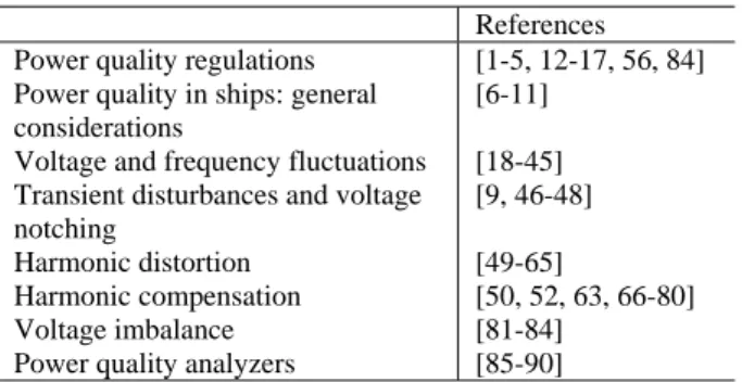
Transients in shipboard power system networks are normally produced by switching on/off of large power loads or by pulsating loads. Fig. 3 shows a transient disturbance in the voltage waveform recorded in a 400 V sub-system of an all-electric ship [10].
Fig. 3. Transient disturbance in voltage waveform in an all-electric ship [10].
There is no standard method for their detection and analysis. There are different methods proposed in the literature, both in the time domain or in the frequency domain, although none of them is dominant. The magnitude of the high-frequency coefficients of the discrete wavelet transform applied on the voltage samples is proposed in [9], [46] for detection and analysis of transient disturbances and notching in shipboard power system networks. On the other hand, a real-time implementation of the discrete wavelet transform, based on the use of multiple-constant multiplication, is presented in [47] for detection of transient disturbances.
Voltage notching is a type of periodic waveform distortion produced by the normal operation of power electronic converters, extensively used in shipboard power system grids, especially those equipped with electric propulsion systems. Voltage notches occur when the current switches from one phase to another in a power converter. During this period, there is a momentary short circuit between two phases. The severity of the notch is determined by the source inductance between the converter and the point being monitored. Fig. 4 shows an example a voltage waveform with voltage notches due to the operation of a six-pulse converter.
Fig. 4. Voltage notching produced by a six-pulse converter
Voltage notching is a power quality disturbance that falls between transient and harmonic distortion. Since notching occurs continuously and periodically, it can be characterized using the voltage harmonic distortion, but the frequency components associated with notching can be quite high so that they cannot be characterized using conventional harmonic measurement equipment. As in the case of transient disturbances, the international marine standards and the rules of the marine classification societies do not specify any method for detection and analysis of voltage notching. IEEE Std.519:2014 [4] defines a method for characterization of voltage notching and limits for commutation notches and total harmonic distortion factor, but no reference is made to any measurement method. As is shown in Fig. 5, voltage notches are defined using two parameters, the depth and the area. The depth d is defined as the average depth of the line voltage notch from the sine wave voltage and is expressed in percent as d/v · 100%. Notch area, AN, is the product of the notch depth in volts times the width of the notch, t, measured in microseconds (AN=d·t). Table II shows the limits for commutation notches according to [4].
Fig. 5. Definition of notch depth and area
Table II. Recommended limits on commutation notches
Special applications General system Dedicated system Notch depth 10% 20% 50% Notch Area (AN) 16400 22800 36500
The value AN have been developed for 480 V systems. It is necessary to multiply the values given by V/480 for application at all other voltages.
Special applications include hospitals and airports.
A dedicated system exclusively supplies a specific user or user load.
-800 -600 -400 -200 0 200 400 600 800 M a gn iu tu de ( V o lt s ) Time d t= µ sec
A simple method, implemented in a low-cost virtual measurement instrument, is proposed in [48], for detection and estimation of voltage notches using the peak magnitudes and the energy of the high frequency coefficients of the wavelet analysis. A one-level discrete wavelet transform is applied over sampling windows of one-cycle width, using db4 as the mother wavelet and 40 kHz sampling frequency. The magnitude of the high-frequency coefficients of DWT shows a long series of peaks exactly corresponding to the notches in voltage supply. The beginning, the end and the duration of voltage notches can be determined with a time resolution of 0.196 milliseconds (double that of the sampling period of the signal due to the downsampling by two associated with the computation of these coefficients). In addition, the total energy of these coefficients can be used for the assessment of the energy associated with voltage notches, improving the estimation when using higher sampling frequency.
IV.
HARMONIC DISTORTIONHarmonics in voltage and current waveforms are frequency components that are integer multiples of the power system frequency. Harmonics are produced by the connection of non-linear loads, these loads draw non-linear currents which when flowing through the power system impedances produce distortion in the voltage waveform, that finally affects the whole power system.
An important aspect of shipboard power systems is the massive use of non-linear loads in comparison to power system network on land. The generalized use of any type of power converters in marine applications, such as main propulsion, thrusters, compressors or pumps, has increased in such a way that the non-linear loading in current merchant and navy vessels can reach up to 80% of the onboard generation capacity [49]. A description of the main harmonic producing loads in ship power systems is given in [50] and a simulation model in ATP to study the voltage and current distortion on the low voltage busbars caused by many frequency converters in a naval system is presented in [51]. In addition, the relative high source impedance of onboard supply generators, with respect to the inland transformer power, can cause excessive levels of voltage distortion for a given harmonic load. As is reported in [52], the magnitude of the total voltage distortion on shipboard power systems can be over 20%.
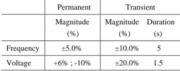
As another consequence of the massive use of power converters, shipboard power system networks present high frequency distortion and a high magnitude of interharmonic distortion in voltage and current waveforms, higher than the one existing in inland power networks. Interharmonics are frequency components that are not an integer multiple of power system frequency. In the case of shipboard power system networks, and as is reported in [53], these interharmonic components can cover the whole frequency spectrum and greatly deteriorate the voltage and current waveforms, affecting the entire power system. An example of voltage waveform with high harmonic and interharmonic distortion is shown in Fig. 6.
Fig. 6. Voltage waveform recorded on the main switchboard busbar during bow thruster operation [11]
A method based on the modulation theory is used in [53] to evaluate the interharmonic components generated by current type AC-DC-AC converters in ship propulsion systems. The interharmonic frequencies generated in these power converters are dependent on the propulsion motor speed and can bear any frequency. According to the authors, this method allows the prediction of currents in the network, transformers, power generators and all network impedances. The cross power spectrum method between voltage and current at any node of a power system is used in [54] to determine the magnitude and direction of real and reactive power flow at any frequency of interest, including fundamental, harmonic and interharmonic frequencies.
The effect of harmonic and interharmonic distortion on equipment is well known [50]. It produces additional losses in rotating electric machinery, transformers, cables or capacitors, resonance effects in the power system, malfunction of measurement and control equipment, malfunction of protective devices or interference with electronic equipment, including communication and navigation equipment. A method using the hardware-in-loop simulations is presented in [55] for analyzing and understanding harmonic distortion effects in all-electric ship systems.
Harmonics can be an especially serious problem in explosion-proof motor installations, such as those encountered in LPGs, oil and chemical tankers or oil production platforms, where an increased risk of explosion can result from the overheating produced by high harmonic distortion [52]. To avoid this problem the IEC requires a 2% or 3% distortion level for certification of explosion-proof motors, depending on the type of the specific protection concept [56], the motor losing its certification if these limits are exceeded.
Harmonics are difficult to measure in shipboard power networks because of the frequency variations and the high magnitude of interharmonic distortion. According to standard IEC 61000-4-7, the maximum permissible synchronization error between the sampling window and the power system frequency should not exceed ± 0.03% for harmonic measurement, and this synchronization should be possible within a range of at least ± 5% of the nominal power system frequency [2]. As is reported in [18, 19], frequency variations in shipboard power networks are normally higher than the standard synchronization requirements, so standard harmonic measurements are really difficult in these non stationary conditions.
To cope with this problem different proposals have been made in the technical literature. A comparison of different methods for harmonic estimation in shipboard power networks using Fourier analysis with different sampling windows, synchronization and different interpolation methods is presented in [57]. A special property of the Hanning window is applied in [58] to accurately detect the fundamental frequency of a signal in the presence of harmonic and interharmonic distortion. After obtaining the fundamental frequency, the paper applies the same procedure to all possible harmonics to be filtered for further analysis of interharmonics. The use of distortion indices, other than the standard total harmonic distortion index, more appropriate for the complete characterization of harmonic distortion in shipboard power systems, is proposed in [59-61].
Another important aspect, at present not fully taken into consideration in marine regulations, is the measurement of the waveform distortion over the harmonic range (> 2 kHz). This frequency range is not normally covered by commercial power quality analyzers. It is of increasing concern because the high-frequency nonsynchronous switching techniques used in power converters is increasing the distortion levels in frequency ranges from over 2 kHz up to 50 kHz and beyond. Reference [62] presents the results obtained in the measurement of harmonic distortion up to 50 kHz in an all electric ship, applying the discrete Fourier transform, using rectangular non-synchronized data acquisition windows and grouping the output coefficients in 200-Hz bands. The results obtained are very different when computing the THD index using the standard definition up to harmonics of 40th harmonic order, as in [1], or when using a new extended index covering frequency components beyond this frequency range.
Marine classification bodies are highly concerned with the problem of harmonic distortion and its effect on shipboard installations, introducing strict limits for this disturbance in order to ensure the reliability of marine electric equipment and the safety of crews [52]. According to IEC 60092-101 [12], the THD in voltage supply shall not exceed a 5% limit, with no individual harmonic greater than 3% of the fundamental voltage, no matter what the harmonic order, for ship distribution systems. The same limits are required in [14, 17]. In both cases higher limitations, up to a 10% limit, are allowed in dedicated systems, such as dedicated propulsion switchboards, if all consumers and distribution equipment subjected to the increased distortion level is certified to withstand those harmonic distortion levels. Most of the classification societies have adopted voltage distortion limits similar to DNV and ABS [63]. In contrast, LRS uses a THD limit of 8% of the fundamental voltage at the switchboard or section boards, measured for harmonics up to order 50, but establishes a strict limit of only 1.5% for any individual voltage harmonic above the 25th order. Table III summarizes the limits for voltage harmonic distortion under all operating conditions for shipboard electrical installations of the international organizations and the marine classification societies.
Table III. Maximum voltage distortion under all operating conditions for shipboard electrical installations.
IEC IEEE DNV ABS LRS Total harmonic distortion
Single harmonic 5% 3% 5% 3% 5%** 3% 5% 3% 8% 1.5%* *for harmonics over 25th order
**up to 10% in dedicated systems
However, in spite of the high interharmonic distortion in shipboard power grids (especially in those equipped with electronic converter subsystems), no interharmonic limits are considered in the regulations of the classification societies. The same applies for subharmonics, frequency components under the fundamental frequency, also produced by the normal operation of power converters, and for voltage notching, which, as was mentioned in a previous section, can also be characterized by the high-frequency harmonic distortion produced.
As an alternative to the existing harmonic limits, reference [64] proposes the use of higher harmonic limits than those suggested in the marine regulations, if the electrical ship equipment is documented to withstand those higher limits, or the use of probabilistic harmonic indices as in [65]. On the other hand, the use of different limits depending on the ship operation states (maneuvering, port, navigation) is suggested in [61], because distortion levels change significantly, especially during maneuvering.
Harmonic compensation
Active and passive filters, multipulse drive systems, active front end drives, and others have been used in the marine industry for harmonic compensation in ships to meet the strict limits of the classification societies.
References [50, 52, 63, 66, 67] discuss different harmonic mitigation methods used in the marine industry to meet harmonic limits in ships. The design of passive harmonic filters for different ship systems are presented in [68, 69]. The use of a wide spectrum passive harmonic filter to mitigate voltage and current harmonics is presented in [63, 66, 70]. The advantages of active filters over passive filters in typical marine networks are discussed in [71].
The design of harmonic filters for variable frequency drives in marine vessels is introduced in [72, 73]. The use of parallel active power filters for improving the filtering performance is proposed in [74]. Different control methods of shunt active filters for marine applications are presented in [75, 76]. A combination of passive and active filters is discussed in [77]. Different methods for the optimal placement and sizing of harmonic filters in shipboard power networks are studied in [78, 79]. Finally, the use of reconfigurable induction motor drives with harmonic cancellation features is presented in [80].
V.
VOLTAGE IMBALANCEIn a polyphase system voltage imbalance is defined as a condition in which the r.m.s. values of the line voltages or the phase angles between consecutive line voltages are not all equal [3]. Voltage imbalance can be produced by asymmetrical impedances of distribution lines, unbalanced three-phase loads, asymmetrical transformer winding impedances, open wye and open delta transformer banks or non-uniform distribution of single phase loads. The three-phase voltages are never perfectly balanced because of the continuous switching of single and three-phase loads in power system networks.
Three-phase induction machines, power electronic converters and drives are the most sensitive equipment to voltage imbalance. The detrimental effect of voltage imbalances on induction motors derives from the fact that small imbalances in the three-phase voltages can result in a large imbalance in phase currents, increasing the heating effect and losses, reducing the efficiency and the lifetime of the motor [81-83]. According to NEMA 3.5% of voltage imbalance can result in 25% added heating in different types of induction motors [84]. The mechanical losses and the thermal effects on induction motors can be of such a magnitude that NEMA recommends the de-rating of the motor as a function of the percentage of the voltage imbalance.
According to [5], voltage imbalance of greater than 2% should be reduced, correcting the malfunction causing it. Voltage imbalance greater than 5% can be caused by single-phasing conditions, during which one phase of a three-phase circuit is missing or de-energized. Phase monitors are often required to protect three-phase motors from the adverse effects of single phasing.
VI.
POWER QUALITY ANALYZERSThe monitoring and analysis of power quality in ships, both for evaluation of conformity with the respective standards as well as for trouble-shooting applications, requires dedicated instrumentation adapted for the specific conditions of onboard power quality. Some of the new methods and indices required for the complete characterization of onboard power quality are the following:
• New methods for measurement of the instantaneous power system frequency. • New indices for characterization of voltage and frequency fluctuations.
• New methods for detection and characterization of transients and voltage notching.
• New methods and new indices for measurement of harmonic and interharmonic distortion in the non-stationary conditions of shipboard power system networks.
• New methods and indices for the estimation of harmonics over the harmonic range.
• Methods for measurement of active and reactive power distribution between generators working in parallel, both in stationary and dynamic conditions.
A number of dedicated power quality analyzers have been proposed in the technical literature to cope with these specific requirements. Reference [85] describes the structure and performance of what
is probably the first specialized power quality analyzer for shipboard power systems. A DSP-based instrument designed for proper operation under power frequency fluctuations is described in [86-89]. The chirp z-transform and the complementary use of the discrete wavelet transform and the discrete Fourier transform are proposed in these references for the most accurate estimation of power quality indices in shipboard power system networks. An onboard power quality monitoring system designed to manage and optimize the power consumption of electrical loads is described in [90].
Finally, Table IV summarizes the different proposals reviewed in this paper.
Table III. Power quality in ships
References Power quality regulations
Power quality in ships: general considerations
Voltage and frequency fluctuations Transient disturbances and voltage notching
Harmonic distortion Harmonic compensation Voltage imbalance Power quality analyzers
[1-5, 12-17, 56, 84] [6-11] [18-45] [9, 46-48] [49-65] [50, 52, 63, 66-80] [81-84] [85-90] CONCLUSIONS
The specific characteristics of shipboard power electric power plants make electric power quality a critical factor in the correct performance of onboard electrical equipment. This paper presents a comprehensive, critical literature review of the main contributions in the principal aspects of monitoring and analysis of power quality in ships. Voltage and frequency deviations, transients and voltage notching, fault detection and classification, harmonic distortion, harmonic compensation, voltage imbalance, dedicated power quality instrumentation and power quality regulations are considered, discussing the performance of the different proposals and highlighting the important role that power quality has in modern ships in improving the efficient use of energy, the security of navigation as well as the safety of life at sea.
REFERENCES
[1] EN 50160, Voltage characteristics of electricity supplied by public distribution systems. CENELEC, 2010.
[2] IEC 61000-4-7, Electromagnetic compatibility (EMC) - Part 4-7: Testing and measurement techniques – General guide on harmonics and interharmonics measurements and instrumentation, for power supply systems and equipment connected thereto, 2008.
[3] IEC 61000-4-30, Electromagnetic compatibility (EMC) - Part 4-30: Testing and measurement techniques – Power quality measurement methods, 2015.
[4] IEEE Std. 519-2014, IEEE Recommended Practices and Requirements for Harmonic Control in Electrical Power Systems. IEEE 2014.
[5] IEEE Std. 1159-2009, IEEE Recommended Practice for Monitoring Electric Power Quality. IEEE, 2009.
[6] Mindykowski J. Assessment of electric power quality in ship systems fitted with converter subsystems. Shipbuilding & Shipping Ltd, Gdansk, Poland, 1st ed. 2003.
[7] Jonasson I, Soder L. Power quality on ships – A questionnaire evaluation concerning island power system. In: Proceedings 9th International Conference on Harmonics and Quality of Power, 2000;2:639-44.
[8] Prousalidis J, Muthumuni D. Power quality on electric ships. Pulse 2005; summer;1-3.
[9] Tarasiuk T, Mindykowski J. How to measure and to estimate the power quality parameters in ship systems? In: Proceedings IEEE Instrumentation and Measurement Technology Conference, 2006:1608-13.
[10] Tarasiuk T. A few remarks about assessment methods of electric power quality on ships – Present state and further development. Measurement 2009;42;8:1153-63.
[11] Mindykowski J. Power quality on ships: today and tomorrow’s challenges. In: Proceedings Int. Conference and Exposition on Electrical and Power Engineering, 2014:1-17.
[12] IEC 60092-101, Electric installations in ships – Part 101: Definitions and general requirements. International Electrotechnical Commission 2002.
[13] IEEE Std 45-2002, IEEE Recommended Practice for Electric Installations on Shipboard. IEEE 2002.
[14] Det Norske Veritas. Rules for classification and construction. Ship technology, Seagoing ships, Electrical installations of ships, 2012; part 4; chapter 8.
[15] Lloyd's Register of Shipping. Rules and Regulations for the Classification of Ships, 2014; part 6.
[16] American Bureau of Shipping. Rules for building and classification, Steel Vessels, 2004; part 4, chapter 8.
[17] American Bureau of Shipping. Guidance notes on Control of Harmonics in Electrical Power Systems, 2006.
[18] Mindykowski J, Szweda M, Tarasiuk T. Voltage and frequency deviations in exemplary ship’s network – research for ship owner. EPQU Magazine 2005;1;2:61-67.
[19] Prousalidis J, Mouzakis P, Sofras E, Muthumuni D, Nayak O. On studying the power supply quality problems due to thruster star-ups. In: Proceedings of IEEE Electric Ship Technologies Symposium, 2009:440-48.
[20] Prousalidis J, Styvaktakis E, Sofras E, Hatzilau IK, Muthumuni D. Voltage dips in ship systems. In: Proceedings of IEEE Electric Ship Technologies Symposium, 2007:309-14.
[21] Prousalidis J, Styvaktakis E. Introducing a classification method of voltage dips in ship electric energy systems. J. Mar. Eng. Technol 2008; paper number K010:1-10.
[22] Pallis IK, Georgakopoulos IP, and Tatakis EC. Modern starting methods of large thrusters supplied by the power network of a ship. International Conference on Electrical Machines, 2014:2325-31.
[23] Liu Y, Steurer M, Ribeiro PF. A novel approach to power quality assessment: real time hardware-in-the-loop test bed. IEEE T Power Deliver 2005;20;2:1200-1.
[24] Shin YJ, Monti A, Ponci F, Arapostathis A, Grady WM, Powers EJ, Dougal R. Virtual power quality analysis for ship power system design. In: Proceedings of Instrumentation and Measurement Technology Conference, 2004:1758-63.
[25] Arcidiacono V, Castellan S, Menis R, Sulligoi G. Integrated voltage and reactive power control for All Electric Ship Power Systems. International Symposium on Power Electronics, Electrical Drives, Automation and Motion, 2006: pp. S31-61 to S31-65.
[26] Arcidiacono V, Menis R, Sulligoi G. Improving power quality in All Electric Ships using a voltage and VAR integrated regulator. In: Proceedings of IEEE Electric Ship Technologies Symposium, 2007:322-27.
[27] Arcidiacono V, Monti A, Sulligoi G. An innovative generation control system for improving design and stability of shipboard medium-voltage integrated power system. In: Proceedings of IEEE Electric Ship Technologies Symposium, 2009:152-6.
[28] Arcidiacono V, Monti A, Sulligoi G. Generation control system for improving design and stability of medium-voltage dc power systems on ships. IET Electr Syst Transp 2012;2;3:158-87.
[29] Mitra P, Venayagamoorthy GK. Artificial immune system based DSTATCOM control for an electric ship power system. In: Proceedings of 39th IEEE Annual Power Electronics Specialists Conference, 2008:718-23.
[30] Mitra P, Venayagamoorthy GK. Real time implementation of an artificial immune system based controller for a DSTATCOM in an electric ship power system. In: Proceedings of IEEE Industry Applications Society Annual Meeting, 2008:1-8.
[31] Mitra P, Venayagamoorthy GK. An adaptive control strategy for DSTATCOM applications in an electric ship power system. IEEE Trans. on Power Electronics 2010;25;1:95-104.
[32] Farasat M, Arabali AS, Trynadlowski A. A novel control principle for all-electric ship power systems. In: Proceedings of IEEE Electric Ship Technologies Symposium, 2013:178-184.
[33] Steurer M, Andrus M, Langston J, Qi L, Suryanarayanan S, Woodruff S, Ribeiro PF. Investigating the impact of pulse power charging demands on shipboard power quality. In: Proceedings of IEEE Electric Ship Technologies Symposium, 2007:315-21.
[34] Domaschk LN, Ouroua A, Hebner RE, Bowlin OE, Colson WB. Coordination of large pulsed loads on future electric ships. IEEE T Mgn;43;1:450-5.
[35] Kulkarni S, Santoso S. Impact of pulse loads on electric ship power system: with and without flywhell energy storage systems. In: Proceedings of IEEE Electric Ship Technologies Symposium, 2009:568-73.
[36] Kanellos FD, Tsekouras GJ, Prousalidis J, Hatzilau IK. An effort to formulate frequency modulation constrains in ship-electrical systems with pulsed loads. IET Electr Syst Transp 2011;1;1:11-23.
[37] Kanellos FD, Tsekouras GJ, Prousalidis J, Hatzilau IK. Effort to formulate voltage modulation constrains in ship-electrical systems with pulsed loads. IET Electr Syst Transp 2012;2;1:18-28.
[38] Kim SY, Choe S, Ko S, Sul S-K. A naval integrated power system with a battery energy storage system. IEEE Electrification Magazine 2015;3;2:22-33.
[39] Xie C, Zhang C. Research on the ship propulsion system network power quality with flywheel energy storage. In: Proceedings of Asia-Pacific Power and Energy Engineering Conference, 2010:1-3.
[40] Vicenzutti A, Bosich D, Giadrossi G, Sulligoi G. The role of voltage controls in modern all-electric ships. IEEE Electrification Magazine 2015;3;2:49-65.
[41] Douglas H, Pillay P, Ortmeyer TH. The application of wavelets to shipboard power system protection. In: Proceedings of IEEE Electric Ship Technologies Symposium, 2005:432-6.
[42] Li H, Li W, Luo M, Monti A, Ponci F. Wavelet based method for fault detection in medium voltage dc shipboard power systems. In: Proceedings of IEEE International Instrumentation and Measurement Technology Conference, 2012:2155-60.
[43] Li W, Monti A, and Ponci F. Fault detection and classification in medium voltage DC shipboard power systems with wavelets and artificial neural networks. IEEE T Instrum Meas 2004;64;11:2651-65.
[44] Pan Y, Silveira PM, Steurer M, Baldwin TL Ribeiro PF. A fault location approach for high-impedance grounded DC shipboard power distribution system. In: Proceedings of IEEE Power and Energy Society General Meeting, 2008: 1-6.
[45] Pan Y, Steurer M, Baldwin TL. Ground fault location testing of a noise-pattern-based approach on an ungrounded dc system. IEEE T Ind Appl 2011;47;2:996-1002.
[46] Mindykowski J, Tarasiuk T. Wavelet transform for electrical energy quality analysis on ships. In: Proceedings of IEEE Instrumentation and Measurement Technology Conference, 2002:1431-6.
[47] Guo R, Sloderbeck M, DeBrunner L, Steurer M. Real-time wavelet transform in an electric ship simulation. In: Proceedings of IEEE Electric Ship Technologies Symposium, 2011:463-7.
[48] Barros J, de Apráiz M, Diego RI. Voltage notch detection and analysis using wavelets. In: Proceedings of IEEE International Conference on Virtual Environments, Human-Computer Interfaces, and Measurement Systems, 2008:151-5.
[49] Bourguet S, Guerin P, Le Doeuff R. Non characteristic harmonics generated by frequency converter. In: Proceedings of All Electric Ship, 2003, Edinburg.
[50] Nasiri A. Harmonics in sea and undersea vehicles: sources, effects and solutions. In: Proceedings of International Conference on Vehicle Power and Propulsion, 2005:161-167.
[51] Brenna M, Foiadelli F, Lazaroiu GC, Zaninelli D. Harmonic analysis of the secondary distribution network in naval systems. In: Proceedings IEEE 15th International Conference on Harmonics and Quality of Power, 2012:541-5.
[52] Evans IC, Hoevenaars T. Meeting harmonic limits on marine vessels. In: Proceedings of IEEE Electric Ship Technologies Symposium, 2007:115-21.
[53] Bourguet S, Guerin P, Le Doeuff R. Analysis of interharmonics generated by a ship propulsion system. In: Proceedings of 11th International Conference on Harmonics and Quality of Power, 2004:465-470.
[54] Kim T, Powers EJ, Mack Grady W, Arapostathis A. Real and reactive power analysis for interharmonics. In: Proceedings of IEEE Electric Ship Technologies Symposium, 2005:244-247.
[55] Steurer M, Woodruff S, Real time digital harmonic modelling and simulation: an advanced tool for understanding power system harmonics mechanisms. In: Proceedings of IEEE Power and Energy Society General Meeting, 2004;1:773-6.
[56] IEC 60034-1: 2010, Rotating electrical machines – Part 1: Rating and performance. International Electrotechnical Commission, 2010.
[57] Tarasiuk T. Comparative study of various methods of DFT calculation in the wake of IEC standard 61000-4-7. IEEE T Instrum Meas 2009;58;10:3666-77.
[58] Kondabathini AK, Ginn HL, Molen GM. Accurate method to measure harmonics and interharmonics in shipboard power quality analysis. In: Proceedings of IEEE Electric Ship Technologies Symposium, 2005:255-60.
[59] Tarasiuk T. DBF factors for fast estimation of waveform distortion in ship systems – case study. In: Proceedings of IEEE Instrumentation and Measurement Technology Conference, 2006:1386-91.
[60] Tarasiuk T. The method based on original DBFs for fast estimation of waveform distortions in ship systems – case study. IEEE T Instrum Meas 2008;57;5:1041-50.
[61] Tarasiuk T, Mindykowski J. An extended interpretation of THD concept in the wake of ship electric power systems research. Measurement 2012;45;2:207-12.
[62] Szweda M, Tarasiuk T. An assessment of distortions of supply voltage waveform in all-electric ship power network - Case Study. In: Proceedings of 9th International Conference Electrical Power Quality and Utilisation, 2007:1-6.
[63] Hoevenaars T, Evans IC, Lawson A. New marine harmonic standards. IEEE Industry Applications Magazine 2010:16-25.
[64] Ribeiro PF, Steurer M, Islam M. Re-evaluating electric power system harmonic distortion limits for shipboard systems. In: Proceedings of 11th International Conference on Harmonics and Quality of Power, 2004:706-11.
[65] Suryanarayan S, Ribeiro P, Steurer M. Probabilistic aspects and flexible thresholds of waveform distortions. In: Proceedings of IEEE PES Power Systems Conference and Exposition, 2006:256.
[66] Evans IC, Hoevenaars T. Homing in on harmonics. Offshore Engineer; February 2006:55-7.
[67] Brenna M, Foiadelli F, Roscia M, Zaninelli D. Passive and active filter applications in all-electric ships. In: Proceedings of Fifth International Symposium All Electric Ships, 2005:B1-3.
[68] Liang X, Ilocbonwu O. Passive harmonic filter design scheme for subsea cable applications with six-pulse variable frequency drives. In: Proceedings of IEEE Energy Conversion Congress and Exposition, 2009:597-603.
[69] Su C-L, Hong C-J. Design of passive harmonic filters to enhance power quality and energy efficiency in ship power systems. In: Proceedings of IEEE/IAS 49th Technical Conference on Industrial and Commercial Power Systems, 2013:1-8.
[70] Evans IC. Harmonic mitigation for ac-drive thruster applications. The Naval Architect 2002: July/August:25-6.
[71] Noy P, Jones SR. Active filters in marine applications. In: Proceedings of Second International Conference on Power Electronics, Machines and Drives, 2004;1:367-72.
[72] Giannoutsos SV, Manias SN. Harmonic filter design for variable frequency drives in marine vessels based on a systematic power quality assessment and monitoring methodology. In: Proceedings of IEEE/IAS 50th Industrial & Commercial Power Systems Technical Conference, 2014:1-9.
[73] Giannoutsos SV, Manias SN. A systematic power quality assessment and harmonic filter design methodology for variable frequency drive application in marine vessels. IEEE T Ind Appl 2015: 51;2:1909-19.
[74] Qian T, Lehman B, Bhattacharya A, Ginn H, Molen M. Parallel operation of shunt active power filters for damping of harmonic propagation in electric shipboard power systems. In: Proceedings of IEEE Electric Ship Technologies Symposium, 2005:248-54.
[75] Pigazo A, Moreno VM, Liserre M, Dell’Aquila A. FBD-method based controller for shunt active power filters in marine vessels. IEEE International Symposium on Industrial Electronics, 2008:2253-7.
[76] Mindykowski J, Xu X, Tarasiuk T. A new concept of harmonic current detection for shunt active power filter control. Measurement 2013;46;10:4334-41.
[77] Xu X, Mindykowski J, Zheng H. New concept of power quality improvement method in marine electric propulsion system. In: Proceedings of 11th International Conference on Harmonics and Quality of Power, 2004:211-4.
[78] Guerin P, Miegeville L. Optimal placement and sizing of harmonic filters aboard an electric propulsion ship. IET Gener Transm Dis 2007;1;4:612-8.
[79] Crapse P, Wang J, Abrams J, Shin Y-J, Dougal R. Power quality assessment and management in an electric ship power system. In: Proceedings of IEEE Electric Ship Technologies Symposium, 2007:328-34.
[80] Qian L, Cartes D, Li H, Srivastava SK. A reconfigurable induction motor drive with harmonic cancellation feature. In: Proceedings of IEEE Electric Ship Technologies Symposium, 2005:93-8.
[81] Abreu JPG, Emanuel AE, Induction motor loss of life due to voltage imbalance and harmonics: a preliminary study. In: Proceedings of 9th International Conference on Harmonics and Quality of Power, 2000:1:75-80.
[82] Abreu JPG, Emanuel AE, Induction motor thermal aging caused by voltage distortion and imbalance: loss of useful life and its estimated cost. IEEE T Ind Appl 2002:28;1:12-20.
[83] Gnacinski P. Thermal phenomena in electric machines in the wake of electric power quality in ship’s networks, In: Proceedings of 8th International Conference on Electrical Power Quality and Utilisation, 2005:399-404.
[84] NEMA MG 1-2006, Motors and Generators.
[85] Mindykowski J, Tarasiuk T. Specialized analyser for electrical energy quality estimation in ship electrical power system. In: Proceedings of IEEE Instrumentation and Measurement Technology Conference, 1998:791-6.
[86] Mindykowski J, Szweda M, Tarasiuk T. Measurement equipment for ships' electrical power systems. In: Proceedings of IEEE Instrumentation and Measurement Technology Conference, 2004;2:1367-72.
[87] Mindykowski J, Tarasiuk T. Development of a DSP-based instrumentation for power quality monitoring on ships. Measurement 2010;43;8:1012-20.
[88] Tarasiuk T. Estimator-analyzer of power quality: Part I – methods and algorithms. Measurement;44;1:207-12.
[89] Tarasiuk T. Estimator-analyzer of power quality: Part II – hardware and research results. Measurement 2011;44;1:248-58.
[90] Dallas SE, Skoufis AD, Prousalidis JM. Introducing a ship electric power quality monitoring system for green shipping. In: Proceedings of IEEE International Conference on Electrical Machines, 2014:2312-8.
![Fig. 3. Transient disturbance in voltage waveform in an all-electric ship [10].](https://thumb-us.123doks.com/thumbv2/123dok_es/6825331.278168/6.892.270.614.445.619/fig-transient-disturbance-voltage-waveform-electric-ship.webp)

![Fig. 6. Voltage waveform recorded on the main switchboard busbar during bow thruster operation [11]](https://thumb-us.123doks.com/thumbv2/123dok_es/6825331.278168/9.892.272.626.105.253/fig-voltage-waveform-recorded-switchboard-busbar-thruster-operation.webp)