Volume 8, Issue 19, July 2013
doi:10.3969/j.issn.1673-5374.2013.19.005 [http://www.nrronline.org; http://www.sjzsyj.org]
Gil-Agudo Á, de los Reyes-Guzmán A, Dimbwadyo-Terrer I, Peñasco-Martín B, Bernal-Sahún A, López-Monteagudo P, del
Ama-Espinosa A, Pons JL. A novel motion tracking system for evaluation of functional rehabilitation of the upper limbs. Neural Regen Res. 2013;8(19):1773-1782.
Corresponding author: Ángel Gil-Agudo, M.D., Ph.D., Department of Biomechanics and Technical Aids, National Hospital for Spinal Cord Injury, Toledo, Spain, [email protected].
Received: 2013-03-20 Accepted: 2013-05-10 (N201303048)
Funding: This study was supported by Foundation Rafael del Pino, Foundation of the Spanish National Hospital for Paraplegic Research and Integration (FUHNPAIIN) and INDRA systems. This study was also supported by
CONSOLIDER-INGENIO 2010 program HYPER CSD2009-00067. MICINN (Spain).
Author contributions: Gil-Agudo Á, Peñasco-Martín B and de los Reyes-Guzmán A participated in conceiving the study. Bernal-Sahún A and López-Monteagudo P participated in study design and coordination and drafted the manuscript. Gil-Agudo Á and Pons JL helped to draft the manuscript.
Peñasco-Martín B, de los Reyes-Guzmán A and del Ama-Espinosa A were re-sponsible for data collection and analysis. Dimbwadyo- Terrer I was in charge of clinical evaluation, interven-tion and data collecinterven-tion. All authors approved the final version of this manuscript.
A novel motion tracking system for evaluation of
functional rehabilitation of the upper limbs*****
Ángel Gil-Agudo
1, Ana de los Reyes-Guzmán
1, Iris Dimbwadyo-Terrer
1,
Benito Peñasco-Martín
1, Alberto Bernal-Sahún
2, Patricia López-Monteagudo
2,
Antonio del Ama-Espinosa
1, José Luis Pons
31 Department of Biomechanics and Technical Aids, National Hospital for Spinal Cord Injury, Toledo, Spain 2 Health Department, Indra Systems, Alcobendas, Madrid, Spain
3 Bioengineering Group, Spanish National Research Council (CSIC), Arganda del Rey, Madrid, Spain
Research Highlights
(1) In this study, we developed an inertial sensor-based motion tracking system, a tool for evaluation of the functional rehabilitation of upper limbs after central nervous system injury. The motion track-ing system enabled us to analyze the complex upper limb and head movements in three dimensions according to nine degrees of freedom data from the kinematic models.
(2) The inertial sensor-based motion tracking system can be used to evaluate the functional recov-ery of the upper limbs after central nervous system injury accurately and stably.
Abstract
Upper limb function impairment is one of the most common sequelae of central nervous system in-jury, especially in stroke patients and when spinal cord injury produces tetraplegia. Conventional assessment methods cannot provide objective evaluation of patient performance and the effec-tiveness of therapies. The most common assessment tools are based on rating scales, which are inefficient when measuring small changes and can yield subjective bias. In this study, we designed an inertial sensor-based monitoring system composed of five sensors to measure and analyze the complex movements of the upper limbs, which are common in activities of daily living. We devel-oped a kinematic model with nine degrees of freedom to analyze upper limb and head movements in three dimensions. This system was then validated using a commercial optoelectronic system. These findings suggest that an inertial sensor-based motion tracking system can be used in patients who have upper limb impairment through data integration with a virtual reality-based neurorehabilitation system.
Key Words
INTRODUCTION
Upper limb function impairment is one of the most common sequelae of central nervous system injury[1-2]. Conventionally used as-sessment methods cannot provide objective evaluations of patient performance and the effectiveness of therapies[3]. The most com-mon assessment tools are based on rating scales, which are inefficient when measuring small changes and can yield subjective bi-as[4-7]. An objective quantification of patient performance during rehabilitation can be achieved using instruments to capture motion trajectories and specific details of task exe-cution. Various commercial systems use dif-ferent sensor technologies to accurately track human motion[8-10]. Photogrammetry is based on the analysis of images captured from different positions to estimate the 3D coordinates of active or passive markers. Although this technique is very precise (with errors in the range of ± 1 mm[11]), markers can be occluded during the analysis of com-plex 3D movements of the upper limb, and its use is limited to a laboratory environment. Electromagnetic motion capture systems have been widely used to track human movements in virtual reality applications. While the problem of marker occlusion does not arise with these systems, the electro-magnetic fields they use are subjected to interference and are affected by metallic ob-jects. Inertial measurement units provide another alternative, and these sensors are designed to measure the orientation of an object within a given space. As they provide accurate readings without inherent latency (static accuracy of < 1.0° root mean square and dynamic accuracy of 3° root mean square[11]), these sensors are useful for hu-man motion tracking applications. These devices are robust and several successful examples of inertial measurement unit measurement of upper limb movements have been described[10, 12-13]. However, most iner-tial measurement unit-based motion capture systems have focused on single-joint tasks and not on complex movements such as activities of daily living, which are required for upper limb rehabilitation.
Virtual reality technology is one of the most innovative and promising therapies for the rehabilitation of patients with motor deficits of the upper limb[14]. This approach can in-crease patient motivation, while extracting objective and accurate information enables the patient’s progress to be monitored re-motely. However, it is not yet possible to conduct a full objective kinematic assess-ment of the entire upper limb while per-forming the activities required using virtual reality systems and remote treatment moni-toring. The ability to capture the actual movement of the patient and transfer it to a virtual environment is one of the strengths of virtual reality systems.
Because inertial measurement units are compact, light, resistant to environmental in-terference and easy to wear, they can be used as a motion capture system for virtual reality applications. The aim of this study was to develop and validate a motion capture system to analyze complex tasks performed using the upper limbs that are common in activities of daily life. Accordingly, we de-signed a suitable inertial measurement unit-based motion tracking system, and de-veloped and validated a kinematic model with nine degrees of freedom that allows upper limb and head movements to be appropriately analyzed. These data can then be incorpo-rated into a virtual reality-based rehabilitation device known as “Toyra”.
RESULTS
The accuracy of the system
Joint movement was analyzed simultane-ously using the Xsens system (the inertial sensor motion capture system using the proposed kinematic model) and the Codamotion system (a commercial human engineering metrological system)[12], inertial sensor-based motion tracking systems. The greatest difference in the range of motion values calculated by each system was found for wrist flexion-extension movement, which differed by 10.18° (129.41° ± 18.69 vs. 139.59° ± 6.52 for Xsens and Codamotion systems, respectively) (Table 1).
Conflicts of interest: None declared.
Ethical approval: The guidelines of the Declaration of Helsinki were followed and the study design was approved by the Local Ethics
Committee of the National Hospital for Spinal Cord Injury, Toledo, Spain.
Author statements: The manuscript is original, has
To compare the captured data from both systems, the difference (distance) between the two sets of data was analyzed point by point in each sample. The final meas-ure was the mean of all differences (distances) calcu-lated by means of Student’s t-test (Table 2).
The P value was calculated to see if there were signifi-cant differences between these distances. With the ex-ception of head inclination, there were no significant dif-ferences observed between the two sets of data (Xsens and Codamotion systems) obtained for any of the mag-nitudes analyzed.
To compare the increasing or decreasing trend of the captured data across both systems (Xsens and
Codamotion), the Pearson’s correlation coefficient (r
value) was applied. Values between 0.95 and 1 were obtained for all the magnitudes measured, even those for which the mean was particularly high (Table 2). Thus, there was a great similarity between captured data in spite of the difference expressed in Table 1.
The system’s robustness–drinking task test
Data obtained by the inertial sensor-based motion capture system using the proposed kinematic model for analyzing an activity of daily living (drinking from a cup) were com-pared with a previous study using Codamotion[12]. Data are shown graphically in Figure 1. Figure 1 shows the range of motion for each degree of freedom using means of the mean and standard deviation of the maximum and minimum values. For example, in shoulder flex-ion-extension, the maximum, a positive value, is a flexion value, and the minimum is negative, indicating an exten-sion value for the shoulder joint. Figure 1 shows that both technologies possessed the required robustness for the measurement and analysis of human movements.
DISCUSSION
The objective of the present study was to develop and validate a motion capture system to analyze functional movements such as activities of daily living. In this study, we used inertial measurement units to design a suitable motion tracking system, and developed and validated a kinematic model with nine degrees of freedom that ena-bled complex upper limb and head movements to be analyzed. This system is currently being incorporated into a virtual reality-based rehabilitation device known as “Toyra”.
Table 1 Simultaneous analysis of joint movement using the Xsens and Codamotion systems (joint angle [°])
Joint trajectory
Maximum Minimum Range of motion
Xsens Codamotion Xsens Codamotion Xsens Codamotion
Shoulder
Flexion 157.76±13.03 159.25±11.69 –4.38±15.57 –4.89±12.20 162.14±19.59 164.14±13.86 Abduction 170.11±3.25 167.03±2.68 –6.23±0.47 2.59±0.37 176.34±2.89 169.62±2.64 Rotation 92.74±10.54 91.35±16.44 –49.39±5.67 –50.66±5.25 142.13±16.10 142.00±21.60 Elbow
Flexion 153.92±3.40 150.67±1.04 11.81±8.25 10.20±8.61 142.10±4.86 140.47±9.61 Pronation-supination 41.46±2.32 38.87±0.41 –75.96±0.86 –77.75±4.37 117.42±1.46 116.62±3.97 Wrist
Flexion 54.06±22.05 67.40±4.58 –75.35±3.35 –72.19±1.94 129.41±18.69 139.59±6.52 Radial-ulnar deviation 28.74±5.18 25.05±4.47 –26.07±4.01 –26.93±3.71 54.81±1.17 51.98±0.79 Head
Flexion 32.70±5.18 35.16±5.31 –57.41±7.82 –57.10±8.59 90.12±12.94 92.27±13.83 Inclination 19.33±7.52 27.94±10.06 –41.59±6.79 –31.61±7.12 60.92±4.54 59.55±4.94
Results were expressed as mean ± SD.
Table 2 Comparison of the fluctuation of the same data (joint angle [°]) (experiment 1)
Joint trajectory Joint angles (difference)
(mean±SD) P r Shoulder
Flexion-extension 0.76±4.04 0.849 0.998 Abduction-adduction 0.69±10.47 0.851 0.991 External-internal
rotation
–0.65±5.67 0.820 0.992
Elbow
Flexion-extension –0.54±2.63 0.880 0.999 Pronation-supination –5.16±4.50 0.094 0.991 Wrist
Flexion-extension 3.47±9.43 0.254 0.974 Radial-ulnar deviation –2.19±4.64 0.068 0.954 Head
Flexion-extension 1.58±1.34 0.424 0.999 Inclination –8.24±2.10 0.000 0.993
Student’s t-test was applied to analyze the difference (distance) between the numeric data obtained by means of both systems (Codamotion and Xsens technologies). r value is Pearson’s
The accuracy of our system was tested by measuring single-joint upper limb movements using a photogram-metric system, Codamotion, and the inertial measure-ment units, revealing similar results for both systems. The robustness of our system was also assessed by measuring a drinking activity using only the inertial measurement units, which produced comparable results to those reported previously using Codamotion[9]. Unlike previous studies[3, 8, 12], nine degrees of freedom (two in the head, three in the shoulder, two in the elbow and two in the wrist) were involved in the use of the inertial measurement unit-based system for the analysis of head movements in this study. We also developed a new kinematic model by modifying a method proposed pre-viously[15]. The findings from the present study demon-strate the accuracy of the proposed system and the as-sociated biomechanical model as well as their suitability for clinical use.
The measurement of complex movements performed by the upper limbs using the inertial measurement unit-based measurement system described here pro-vided results similar to those previously obtained using other measurement systems based on kinematic mod-els[16-21]. Simultaneous recordings of movements using the Xsens and Codamotion systems revealed that range of motion values for shoulder, elbow and wrist were comparable to those of previous studies[16-21]. Several considerations should be taken into account when interpreting these results. First, the results
ob-tained at the shoulder vary greatly from one study to the next due to the complexity of this joint, and they are strongly influenced by the particular model applied. Thus, while the range of motion values for shoulder flexion and abduction closely matched previously re-ported values[9], they were higher than those reported in other studies[16-17]. Moreover, to account for the dis-placement of the scapula, we did not model the shoul-der as a single joint, unlike previous studies [16-17]. This difference in the experimental approach may have fur-ther contributed to the divergent findings. The range of motion values obtained for shoulder rotation were sim-ilar to those previously reported using sensor-based measurement systems[17-18] but they were lower than those reported in goniometry studies[19-20]. Range of motion values for elbow pronation-supination in the present study were also lower than previously reported values (117.42° versus 160–180°)[17-21]
.
For head movements, the flexion-extension range of motion values was comparable to those reported previ-ously[20, 22], although the lateral inclination range of mo-tion values was lower in magnitude, possibly because subjects were requested not to reach the maximum point of their trajectory when performing these movements in order to avoid occlusion of the Codamotion markers. Significant differences in head inclination were found between the curves generated by the Codamotion and Xsens systems, which may have resulted from misa-lignment of the local coordinates for the inertial sensors
Figure 1 Joint angles in the activity of daily living (drinking task test) obtained by the inertial sensor-based motion capture system compared with a previous study[12].
and the Codamotion markers. Thus, despite obtaining a mean error of –8.24° and detecting significant differ-ences in magnitude only, we obtained a correlation of 0.9932.
Strikingly, the range of motion values for shoulder rota-tion and pronarota-tion-supinarota-tion were lower than the joint’s anatomical range of motion[20], which may be because of a displacement of the sensors and markers in relation to the bone structure. Although our model assumes an in-variable shape and size of each body segment, muscle and skin displacement in relation to the bone does oc-cur[23].
The mean errors obtained using the Codamotion system were lower than those previously reported[12, 24], which may reflect methodological differences. In one study[24], gait was analyzed using sensors in which foot contact with the ground resulted in inertial acceleration peaks and a subsequent loss of accuracy[25]. By contrast, in the other study, photogrammetry markers were not placed in the same positions as inertial sensors, creating an addi-tional source of error due to the relative displacement between sensors and markers[12]. Interestingly, the mean errors obtained for the shoulder joint were lower than those for the wrist, possibly because sensors in more distal positions are subjected to greater linear accelera-tion, making the Kalman filter less precise[25].
It should be noted that the activity of daily life drinking task was not recorded simultaneously with photogram-metric and inertial sensor-based systems. Due to the complexity of this movement and the localization of the sensors and markers at the same sites, some of the markers were hidden for the majority of the drinking task cycle, precluding simultaneous analysis. Thus, the re-sults of the drinking task were compared with those of the control groups in two previous studies, one of which was conducted by our group[9, 26]. These results (range of motion and errors) allowed us to evaluate the accuracy of the system, a comparison that was designed to assess the robustness of the kinematic model used, with the modifications proposed, when analyzing a complex hu-man movement.
While the results obtained for flexion and rotation of the shoulder joint were similar to previous findings[9, 26-27], some differences were observed in the maximum am-plitude of abduction of this joint with respect to our pre-vious study[9]. This discrepancy may be due to the drinking style of the subject who performed the task: some subjects kept their elbow close to the body while
others moved it away from the body when drinking[26-27]. The maximum and minimum values for prona-tion-supination, and flexion and extension of the elbow, were lower than those obtained previously[13]. However, the greatest differences were observed for wrist flex-ion-extension, possibly because the participants in the previous study[9] began this task with the wrist in a neu-tral pronation-supination and flexion-extension position, while those in the present study could freely adopt the starting position of their choice.
The sources of error that might affect the particular sys-tem used should be considered when analyzing the re-sults. In addition to the errors inherent to a system of this kind, including measurement errors or misalignment between the local coordinates of the sensors and the real coordinates of the joints, the relative displacement of the sensors in relation to the bone also affects the final re-sults. This error mainly affects the measurement of the amplitude of shoulder rotation and the elbow prona-tion-supination. As sensors cannot be attached to bony prominences, this error can be minimized using a cali-bration process, as described previously[12]. This calibra-tion involves assessing full shoulder rotacalibra-tion with mark-ers placed on bony prominences, thereby minimizing the effect of displacement relative to the bone. The recorded signal is taken as the calibration signal. To correct for the effect of displacement of the inertial measurement units, the same movement (full shoulder rotation) is performed and the results are compared with the calibration signal to generate a correction function[12]. Another common source of error in inertial sensor-based systems is the drift introduced when calculating orientations using inte-gration methods. In the present study, we used orienta-tions provided by the sensors and those were calculated using a Kalman filter. As such, no drift was observed during the recording process.
SUBJECTS AND METHODS
Design
A descriptive study.
Time and setting
This study was performed at the Department of Biome-chanics and Technical Aids, National Hospital for Spinal Cord Injury, Toledo, Spain in January 2012.
Subjects
A 30-year-old healthy right-handed male volunteer par-ticipated in the study after providing informed consent. The man underwent a physical examination to exclude any potentially serious pathology.
Methods
System description
We developed a motion tracking system using commer-cially available Xsens MTx inertial sensors (Xsens Dy-namics Technologies, the Netherlands). These MTx iner-tial measurement units integrate a tri-axis accelerometer, tri-axis gyroscope, tri-axis magnetometer, and a tempera-ture sensor to correct for temperatempera-ture dependence. The position and angle of an inertial sensor cannot be correctly determined through integration methods, due to the noise and fluctuation of the offsets. Thus, the orientation of the MTx is computed by means of a Kalman Filter[28]. This filter uses the input from the rate gyroscopes, accelerom-eters and magnetomaccelerom-eters to provide an accurate optimal estimate of the 3D orientation with very little drift[28]. In a homogeneous earth’s magnetic field, the MTx system provides an angular resolution of 0.05° root mean square, static accuracy of < 1.0° root mean square and dynamic accuracy of 3° root mean square[11].
We used a set of five interconnected inertial measure-ment units that were connected wirelessly (Bluetooth) to a computer via a digital data bus (Master Xbus), which was responsible for the synchronization, data collection and transmission.
Kinematic model
While the inertial sensors provided information on the orientation of each body segment, a biomechanical model was required to calculate the angular magnitudes of clini-cal relevance on the basis of each orientation. The kine-matic models commonly used to describe human motion are based on the Euler method, and thus the results de-pended on the sequence of rotations used[29]. By contrast, each magnitude was unequivocally represented in our
model to aid the interpretation of the results.
The model proposed here considered only the head and the upper limbs. The upper limb was considered as a chain of three rigid bodies joined by the shoulder, elbow and wrist joints. This representation relies on several assumptions:
1. The head is considered to be a rigid solid object linked to the trunk by a hinged joint with two degrees of freedom, flexion-extension and lateral inclinations.
2. The shoulder joint is modeled as a spherical joint with three degrees of freedom. While the clavicle or scapula should also be included to provide a comprehensive representation of movement of the shoulder complex, these measurements were not performed for the follow-ing reasons. First, we sought to develop a simple system using as few sensors as possible, with only five inertial sensing units to monitor the hand, forearm, humerus and head. Secondly, in the case of the clavicle, inertial measurement unit attachment was quite difficult due to the small surface area available. Although inertial meas-urement units have been successfully attached to the scapula in other studies, demonstrating that scapulohumeral rhythm can be measured with minimal cross-talk[16], placing an inertial measurement unit over the scapula requires that the user’s back be unclothed, which increases the set-up time and causes certain dis-comfort.
3. The forearm was considered to be a rigid body, and thus the pronation-supination movement was reallocated to the elbow as an additional degree of freedom in this joint[30]. The elbow was modeled as a hinged joint with two degrees of freedom, flexion-extension and prona-tion-supination.
4. The hand was considered to be open and was mod-eled as a single rigid body. The wrist was modmod-eled as a Cardan joint with two degrees of freedom.
5. Each segment, including bones and soft tissues, had similar rigid body motions. The deformation of soft tis-sues did not significantly affect the mechanical properties of a segment as a whole[23].
The kinematic chain proposed in this model consists of nine degrees of freedom: two in the head (flex-ion-extension and lateral inclinations), three in the shoul-der joint (flexion-extension, abduction-adduction and ex-ternal-internal rotation), two in the elbow joint (flex-ion-extension and pronation-supination) and two in the wrist (palmar-dorsal flexion and radial-ulnar deviation).
using planes and local coordinate systems in the human body, the angular magnitudes calculated did not depend on the user's position with respect to the global coordi-nate system.
A total of five MTx inertial measurement units were used to capture movements of the head and the right upper limb. The inertial measurement units were strategically placed on the trunk, the back of the head, the right arm, the forearm and the hand. The sensor in the trunk was mounted on a rigid mobile structure to align the Y axis of the sensor with the spinal cord. The forearm sensor was positioned distally to minimize displacement in relation to the bone (Figure 2).
Computation of joint angles
Each movement was defined independently using the planes and reference axes of the human body. To meas-ure movements of one segment relative to the previous segment in the chain, it was necessary to define a local coordinate system for each segment. This reference sys-tem included three unitarian and orthogonal vectors. As a global reference, we defined a reference system fixed to the trunk (t1, t2 and t3: Figure 3), where: vector
t1 follows the straight line from one shoulder to another; vector t2 follows the frontal axis in the anterior direction; and vector t3 follows the vertical axis, completing an orthogonal base (t3 = t1 x t2). This reference system is centered on the base of the trunk (Figure 3).
The local coordinate system of the arm (h1, h2 and h3) was established with the arm abducted at 90°, with the palm facing forward (Figure 4). This system is referenced to the center of the shoulder joint, where: vector h1 fol-lows the longitudinal axis of the arm, fixed to the humerus, from the shoulder to the elbow; vector h2 fol-lows the antero-posterior axis in the anterior direction; and vector h3 represents the cross product of vectors h1
and h2 (h3 = h1 x h2).
In the forearm (Figure 4): vector f1 follows the longitudi-nal direction of the forearm from the elbow to the wrist; vector f3 is perpendicular to f1 and parallel to the wrist from the ulnar to the radial styloid; and vector f2 com-pletes the reference system (f2 = f3 x f1). The neutral position of the forearm is defined in relation to the humerus when the arm is completely extended (h1 is parallel to f1) with the palm of the hand in a medial posi-tion.
The local reference system of the hand describes its movements with respect to the forearm and in the pro-posed model, and the hand is represented as a single rigid body. The hand is considered open, facilitating the definition of the vectors: vector m1 runs over the palm of the hand, from the center of the wrist joint to the fingers; vector m2 runs perpendicular to the palm of the hand;
Figure 2 Placement of inertial sensors.
(A) Frontal view; (B) posterior view. The sensors were located on the trunk (1), the back of the head (2), the right arm (3), the forearm (4) and the hand (5).
Figure 4 The avatar represents the upper limb’s movement performed by the 30-year-old right-handed male.
The figure shows the local reference systems of the arm (h1, h2, h3), forearm (f1, f2, f3) and hand (m1, m2, m3). The blue color represents the anterior-posterior axis, the yellow color the medial-lateral axis, and the red color the longitudinal axis.
Figure 3 The avatar represents the movement performed by the 30-year-old right-handed male.
and vector m3 represents the cross product of vectors
m1 and m2 (Figure 3).
The model used to calculate the angular magnitudes was based on a model previously proposed[15]. The definition of the angles relative to the shoulder was modified slightly, as the authors of the previous study did not es-tablish an unequivocal relationship between the position of the arm and the value of each magnitude.
(1) Shoulder flexion: this is represented by the angle formed between the upper arm and the coronal plane. When h1 is below the transverse plane, it can be calcu-lated as π/2 radians minus the angle formed between the
h1 and t2 vectors, and as π/2 plus the angle formed
between h1 and t2 when h1 is over the transverse plane. (2) Shoulder abduction: this is represented by the angle formed between the upper arm and the sagittal plane. When h1 is below the transverse plane it can be calcu-lated as π/2 radians minus the angle formed between h1
and t1 vectors, and as π/2 plus the angle formed
be-tween h1 and t1 when h1 is over the transverse plane. (3) Shoulder rotation: defined as the angular movement of the humerus over its own longitudinal axis (i.e., over vector h1).
(4) Elbow flexion: this is defined as the angle between the f1 and h1 vectors, according to the neutral position defined when the arm is completely extended.
(5) Forearm pronation: this is defined as the angular movement of the forearm over its own longitudinal axis (i.e., over vector f1).
(6) Radial-ulnar deviation: this is the angle formed by vector m1 and the plane that includes vectors f1 and f2. This angle can be calculated as π/2 radians minus the angle between m1 and f3.
(7) Palmar flexion of the wrist: this is the angle formed by vector m1 and the plane that includes vectors f1 and f3. This angle can be calculated as π/2 minus the angle between m1 and f2.
(8) Head flexion: this is defined as the angle between vector he3 and the plane that includes vectors t1 and t3. This angle can be calculated as π/2 minus the angle between he3 and t2.
(9) Head inclination: this is the angle formed by the vec-tor he3 and the plane that includes vectors t2 and t3. This angle can be calculated as π/2 radians minus the angle between he3 and t1.
Validation procedure
The system was validated in vivo in two experiments carried out on different days. The first assessed the ac-curacy of the proposed inertial measurement unit system
in measuring upper limb kinematics in a clinical envi-ronment, while the second assessed its robustness.
Testing the accuracy of the system
The accuracy of the proposed inertial sensor-based measurement system and the biomechanical model de-scribed above was validated using a clinically recognized procedure with kinematic analysis equipment (Codamotion: Charnwood Dynamics Ltd, UK), a photo-grammetry system based on active markers. This system has active markers that emit infrared light that could be recorded by scanning units (cx1).
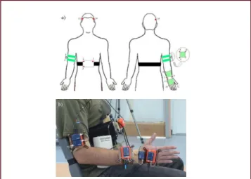
Set-up and procedure: Single-joint upper limb move-ments were recorded simultaneously in the selected subject using two motion capture systems, Codamotion and inertial measurement units. A set of 15 active mark-ers was used to capture movement with the photo-grammetry system on the basis of a previously described model[5]. These markers were distributed on five rigid structures to minimize the potential error resulting from marker displacement over the skin surface, and each was placed on the body segments to be analyzed: trunk, head, arm, forearm and hand. Each structure contained three active markers and one inertial measurement unit, and accordingly, simultaneous measurements were ob-tained with both motion tracking systems in the same environmental conditions (Figure 5).
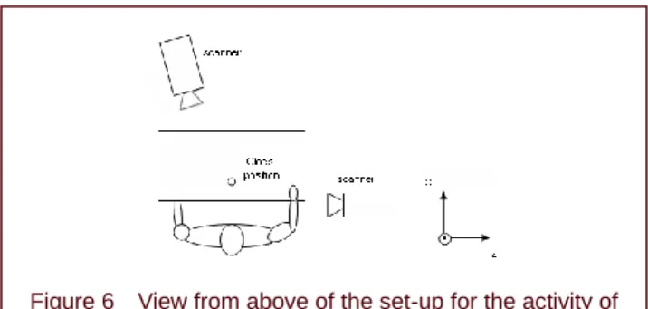
Two Codamotion scanner units (cx1) were used, one placed in front of the subject, slightly to one side with respect to the midline and contralateral to the instru-mented arm of the subject, and the second positioned
Figure 5 Placement of Codamotion markers and inertial measurement units (IMUs) simultaneously.
laterally[9] (Figure 6). The subject was instructed to per-form each of the following nine single-joint-angle tasks three times: head flexion-extension and lateral inclina-tions; shoulder rotations, flexion-extension and abduc-tion-adduction; elbow flexion-extension and prona-tion-supination; wrist flexion-extension and ulnar-radial deviations. In each repetition, the subject cyclically exe-cuted the movement three times.
Data analysis: Data were obtained from nine movement cycles for each task and the data from both measure-ment systems were collected simultaneously. A sampling frequency of 200 Hz was used for Codamotion photo-grammetry recordings and of 25 Hz for the MTX inertial sensor systems. The first processing step involved ap-plying a decimation process to the photogrammetry re-cordings for frequency equalization. Thus, the sampling frequency was set to 25 Hz, the same frequency as that used in the virtual reality-based rehabilitation platform with which we sought to integrate our system.
The orientation matrices of each segment were derived from the position of the photogrammetry markers. These matrices for the inertial measurement units were provided directly, and thus did not need to be calculated. The an-gular magnitudes of interest were calculated for the re-cordings obtained with both systems, as indicated in the description of the kinematic model, and the results were converted from radians to degrees. To assess the differ-ences between the systems for each task, the mean and standard deviation (SD) were computed for each variable. Based on previous studies[17-18], the following kinematic variables were included in the present study: maximum value, minimum value, and the difference between maxi-mum and minimaxi-mum values (i.e., the range of motion). These variables were calculated for the following joint trajectories: flexion-extension, abduction-adduction and external-internal rotation of the shoulder joint; flex-ion-extension and pronation-supination of the elbow joint; palmar-dorsal flexion and radial-ulnar deviation of the wrist;
and flexion-extension and lateral inclination of the head. The data were processed using MATLAB software version R2007b (Mathworks, United States).
Testing the robustness of the system with a drinking task
After demonstrating a high degree of accuracy by com-paring our system with the established Codamotion sys-tem, we analyzed its performance in measuring complex activities, such as those associated with activities of daily living. Thus, we analyzed its performance in a drinking task performed by the same subject registered in Ex-periment 1 using only the validated inertial measurement units, comparing the results with those of a previous study in which the same task was analyzed in similar subjects using the same experimental set-up, but with the Codamotion system using the same marker positions as described previously[9].
Set-up and procedure: The five inertial measurement units were attached to the five rigid structures used in the previous experiment, without the active markers of the photogrammetry system. The experimental set-up (ject starting position, seating configuration, sub-ject-to-table distance, glass position) was identical to that used in the previous study (Figure 6). The subject was instructed how to perform the drinking task, which in-volved reaching out for the glass from the starting posi-tion, grasping it, raising the glass to the mouth, drinking, lowering the glass to the pickup point, and returning the hand to the starting position. This activity was practiced twice to establish a comfortable sitting position before the exercise was recorded[9]. Movements were recorded as the subject executed the drinking task at a comfortable, self-selected speed. Three recordings were obtained for analysis and processing.
Data analysis: To assess the differences between the results of this and a previous experiment[9], the mean and SD were computed for each variable. The variables an-alyzed were the same as those described for the accu-racy experiment.
Statistical analysis
The descriptive statistical analysis was performed using the mean and SD. To compare the results obtained using the Codamotion and Xsens MTx inertial sensors, we calculated the mean and the SD (the distance between two samples of data) obtained with both systems for each degree of freedom analyzed, comparing point by point, using Student’s t-test. The Pearson’s correlation
coefficient was applied to analyze the trend (fluctuation)
Figure 6 View from above of the set-up for the activity of drinking from a glass.
between the numeric data from both systems (Codamotion and MTX inertial sensor systems). All sta-tistical analyses were performed using SPSS 12.0 soft-ware (SPSS, Chicago, IL, USA) and P < 0.05 was con-sidered statistically significant.
REFERENCES
[1] Parker VM, Wade DT, Langton Hewer R. Loss of an arm function after stroke: measurement, frequency and re-covery. Int Rehabil Med. 1986;8:69-73.
[2] Nakayama H, Jorgensen HS, Raaschou HO, et al. Com-pensation in recovery of upper extremity function after stroke: the Copenhagen Stroke Study. Arch Phys Med Rehabil. 1994;75:852-857.
[3] Zhou H, Huosheng H, Tao Y. Inertial measurements of upper limb motion. Med Bio Eng Comput. 2006;44:479-487. [4] Catz A, Itzkovich M, Agranov E, et al. SCIM-spinal cord
independence measure: a new disability scale for patients with spinal cord lesions. Spinal Cord. 1997;35:850-856. [5] Finch E, Brooks D, Stratford PW, et al. ‘Physical
Rehabilita-tion Outcome Measures: A Guide to Enhanced Clinical Deci-sion Making’. BC Decker Inc, Hamilton, Ontario. 2002. [6] Mahoney FI, Barthel DW. Functional evaluation: the
Barthel Index. Maryland State Med J. 1965;14:61-65. [7] Wade DT. Measurement in neurological rehabilitation.
Curr Opin Neurol Neurosurg. 1992;5:682-686.
[8] Biryukova EV, Roby-Brami A, Frolov AA, et al. Kinematics of human arm reconstructed from spatial tracking system recordings. J Biomech. 2000;33:985-995.
[9] de los Reyes-Guzmán A, Gil-Agudo A, Peñasco-Martín B, et al. Kinematic analysis of the daily activity of drinking from a glass in a population with cervical spinal cord injury. J Neuroeng Rehabil. 2010;7:41.
[10] Zhu R, Zhou Z. A real-time articulated human motion tracking using tri-axis inertial/magnetic sensors package. IEEE Trans Neural Sys Rehabil Eng. 2004;12:295-302. [11] Zhou H, Hu H. Human motion tracking for rehabilitation-A
survey. Biomed Signal Process Contr. 2008;3:1-18. [12] Pérez R, Costa U, Torrent M, et al. Upper limb portable
mo-tion analysis system based on inertial technology for neurorehabilitation purposes. Sensors. 2010;10:10733-10751.
[13] Tao Y, Hu H, Zhou H. Integration of vision and inertial sensors for home-based rehabilitation. In: IEEE International Confer-ence on Robotics and Automation, Barcelona, Spain. 2005. [14] Chen CH, Jeng MC, Fung CP, et al. Psychological bene-fits of virtual reality for patients in rehabilitation therapy. J Sport Rehabil. 2009;18:258-268.
[15] Gil-Agudo A, Del Ama-Espinosa A, Pérez-Rizo E, et al. Upper limb joint kinetics during manual wheelchair pro-pulsion in patients with different levels of spinal cord injury. J Biomech. 2010;43:2508-2015.
[16] Cutti AG, Giovanardi A, Rocchi L, et al. Ambulatory measurement of shoulder and elbow kinematics through
inertial and magnetic sensors. Med Bio Eng Comput. 2008;46: 169-178.
[17] Magermans DJ, Chadwick EK, Veeger HE, et al. Re-quirements for upper extremity motions during activities of daily living. Clin Biomech (Bristol, Avon). 2005;20:591- 599.
[18] van Andel CJ, Wolterbeek N, Doorenbosch CA, et al. Complete 3D kinematics of upper extremity functional tasks. Gait Posture. 2008;27:120-127.
[19] Hamilton N, Weimar W, Luttgens K. Kinesiology: Scientific Basis of Human Motion. 9th ed. Mishawaka, IN, USA: Madison, Brown & Benchmark Publishers. 1997.
[20] National Aeronautics and Space Administration (NASA), Man-Systems Integration Standards, Volume I, pp 32-79.
Available online:
http://msis.jsc.nasa.gov/sections/section03. htm Ac-cessed 5 July 2011.
[21] Ryu JY, Cooney WP 3rd, Askew LJ, et al. Functional ranges of motion of the wrist joint. J Hand Surg Am. 1991;16:409-419.
[22] Antonaci F, Bulgheroni M, Ghirmai S, et al. 3D kinematic analysis and clinical evaluation of neck movements in pa-tients with whiplash injury. Cephalalgia. 2002;22:533-542. [23] Rocon E, Pons JL. Case study: study of tremor charac-teristics based on a biomechanical model of the upper limb. In: Pons JL, ed. Wearable Robots: Biomechatronic Exoesqueleton. Chichester, England: John Willey & Sons Ltd. 2005.
[24] Liu K, Liu T, Shibata K, et al. Novel approach to ambula-tory assessment of human segmental orientation on a wearable sensor system. J Biomech. 2009;42:2747-2752. [25] Forner-Cordero A, Mateu-Arce M, Forner-Cordero I, et al. Study of the motion artefacts of skin-mounted inertial sensors under different attachment conditions. Physiol Meas. 2008;29:N21-31.
[26] Murphy MA, Sunnerhagen KS, Johnels B, et al. Three-dimensional kinematic motion analysis of a daily activity drinking from a glass: a pilot study. J Neuroeng Rehabil. 2006;3:18.
[27] Alt Murphy M, Willén C, Sunnerhagen KS. Kinematic variables quantifying upper-extremity performance after stroke during reaching and drinking from a glass. Neurorehabil Neural Repair. 2011;25:71-80.
[28] Xsens Motion Technologies. Available online: http://www. xsens.com/(accessed on 7 July 2011) .
[29] Andrews JG. Euler’s and Lagrange’s equations for linked rigid-body models of three-dimensional human motion. In: Allard P, Stokes IAF, Blanchi JP, eds. Three-dimensional Analysis of Human Movement. Champaign, IL, USA: Human Kinetics. 1995.
[30] Abdullah HA, Tarry C, Datta R, et al. Dynamic biome-chanical model for assessing and monitoring robot-assi- sted upper-limb therapy. J Rehabil Res Dev. 2007;44:43- 62.
![Table 1 Simultaneous analysis of joint movement using the Xsens and Codamotion systems (joint angle [°])](https://thumb-us.123doks.com/thumbv2/123dok_es/6824099.835359/3.892.89.817.163.420/table-simultaneous-analysis-joint-movement-xsens-codamotion-systems.webp)
![Figure 1 Joint angles in the activity of daily living (drinking task test) obtained by the inertial sensor-based motion capture system compared with a previous study [12]](https://thumb-us.123doks.com/thumbv2/123dok_es/6824099.835359/4.892.87.818.125.424/figure-activity-drinking-obtained-inertial-capture-compared-previous.webp)