Integration of Structural Shape Modeling, Optimization and Analysis Methods: Foundations of a New Computer Aided Inventing Strategy and Application to an Engine Crankshaft
130
0
0
Texto completo
(2) Research dissertation. Humberto Aguayo Integration of structural shape modeling, optimization and analysis methods: foundations of a new computer aided inventing strategy and application to an engine crankshaft.. Advisor: Dr.-Ing. Noel Leon. i.
(3) Copyright:. Engineering Division Monterrey Campus ITESM, 2009 All rights reserved. Printed in:. Monterrey, Mexico. ii.
(4) INSTITUTO TECNOLÓGICO Y DE ESTUDIOS SUPERIORES DE MONTERREY CAMPUS MONTERREY. ENGINEERING DIVISION ENGINEERING GRADUATE PROGRAM Committee members recommend that the research project presented by Humberto Aguayo Téllez be accepted as a partial requirement to obtain the academic degree: Doctor in Engineering. Dr. Noel León Rovira Assessor. Dr. Manuel Valenzuela Rendón. Dr. Alberto Hernández Luna Committee member. Committee member. Dr. Víctor Hiram Vázquez Lasso. Dr. Jorge Armando Cortés Ramírez. Committee member. Committee member. Dr. Alex Elías Zúñiga Director of Doctor in Engineering Program.. December, 2009.. iii.
(5) iv.
(6) Abstract Structural optimization has achieved a level of development that makes it possible to go beyond the current limits for optimizing shapes of parts. This kind of optimization also allows designers to improve the traditional design process, helping them to make decisions regarding new inventive shapes and solutions that arise during the shape variation and simulation process. Designers can now take advantage of not only using parametric CAD models to analyze the influence of geometric parameters variations, but also the effect of shape variations on the required performance of their designs. This thesis presents a strategy that allows the designer to perform an automatic search process for crankshaft design objectives based on genetic algorithms, integrated with the simulation of crankshaft behavior, with respect to its balancing and torsion vibrations. At the same time, it looks for an optimal forging process, improved with respect to the design methods used until now. An important characteristic of the strategy presented in this thesis is the automation of the search process, as genetic algorithms through crossbreeding and mutations of the counterweight profile, control the variation of shapes in search for the target balance. At the same time, seek to achieve a target position of the crankshaft’s center of gravity and achieving an optimally forgeable shape.. Keywords: Genetic algorithms, Splines, Crankshaft, TRIZ, FEM. v.
(7)
(8) Acknowledgements I thank to all the people who have contributed to this achievement. I specially thank to my parents Lourdes and Humberto for their love and support. I want to express my gratitude to my advisor Dr Noel Leon for encouraging me to study the Doctorate. I also thank all the professors from Campus Monterrey, Dr. Manuel Valenzuela Rendón, Dr. Alberto Hernández Luna, Dr. Jorge Armando Cortés Ramírez and Dr. Víctor Hiram Vázquez Lasso, members of my committee. I thank Prof. Dr. Ing. Albert Albers for his support during my stay at Karlsruhe University.. vii.
(9)
(10) Dedication To my beloved wife Karool, I could not have done it without you.. ix.
(11)
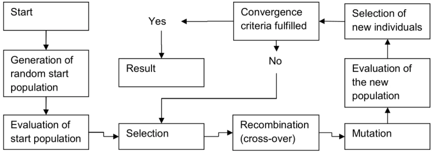
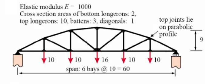
(12) Table of Contents List of figures……………………………………………………………………………………………. 15 List of tables……………...……………………………………………………………….....….…….... 17 Chapter 1. Introduction .......................................................................................................... 19. 1.1. Evolutionary Design .................................................................................................... 20. 1.2. Optimization of Mechanical Systems ........................................................................... 22. 1.3. Shape Optimization Based on Genetic Algorithms ...................................................... 24. 1.4. The Splining Approach ................................................................................................ 26. 1.5. Justification, Hypothesis and Objectives...................................................................... 29. 1.5.1. Justification of the research .................................................................................. 29. 1.5.2. Hypothesis ........................................................................................................... 30. 1.5.3. Objectives ............................................................................................................ 30. 1.6. Conducted methodology for the completion of the research ........................................ 31. Chapter 2. Problem Statement............................................................................................... 33. 2.1. State-of-the-Art in Crankshafts .................................................................................... 34. 2.2. Crankshaft Dynamics .................................................................................................. 39. 2.2.1. Balance basic concepts........................................................................................ 39. 2.2.2. Description of the balance equations.................................................................... 42. 2.3. Chapter conclusions .................................................................................................... 44. Chapter 3. Optimization Methods and Software ..................................................................... 45. 3.1. Optimization Model...................................................................................................... 45. 3.2. Optimization Methods.................................................................................................. 45. 3.3. Use of Genetic Algorithms ........................................................................................... 48. 3.3.1. Darwin’s theory of natural selection in brief .......................................................... 48. 3.3.2. Introduction to Genetic Algorithms....................................................................... 49. 3.3.3. Start population .................................................................................................... 52. 3.3.4. Fitness function .................................................................................................... 52. 3.3.5. Selection .............................................................................................................. 52. 3.3.6. Recombination ..................................................................................................... 53. 3.3.7. Mutation ............................................................................................................... 54. 3.3.8. Replacement strategy .......................................................................................... 55. 3.3.9. Termination criteria............................................................................................... 55. 3.3.10. Genetic algorithms in simulation ........................................................................... 56 11.
(13) 3.3.11. Example of a topology optimization ...................................................................... 57. 3.4. Multi-objective Optimization ......................................................................................... 59. 3.5. Optimization Package: DAKOTA ................................................................................. 62. 3.5.1. How DAKOTA functions ....................................................................................... 62. 3.5.2. The input file format.............................................................................................. 62. 3.5.3. Strategy description.............................................................................................. 64. 3.5.4. Method description ............................................................................................... 64. 3.5.5. Model description ................................................................................................. 64. 3.5.6. Description of variables ........................................................................................ 64. 3.5.7. Interface description ............................................................................................. 64. 3.5.8. Description of responses ...................................................................................... 65. 3.6. Chapter conclusions .................................................................................................... 65. Chapter 4. Development Strategy of the Crankshaft ............................................................. 67. 4.1. First Task: Geometric Optimization of Crankshaft’s Balance ....................................... 69. 4.2. Second Task: Multi-objective Crankshaft Optimization ................................................ 70. 4.3. Third Task: Forging Optimization of Crankshaft’s Dies ................................................ 73. 4.4. Chapter conclusions .................................................................................................... 74. Chapter 5 5.1. Construction of the Model in CAD System ................................................................... 75. 5.1.1 5.2. Deployment of the Implementation ....................................................................... 75 Construction of the counterweights ...................................................................... 77. Imbalance analysis of the crankshaft ........................................................................... 80. 5.2.1. Curvature of the counterweights........................................................................... 84. 5.2.2. Analysis of the Eigen frequencies......................................................................... 85. 5.3. Control Interface for the CAD Model ............................................................................ 86. 5.3.1. Pro/PROGRAM .................................................................................................... 86. 5.3.2. J-LINK .................................................................................................................. 86. 5.3.3. Trail files............................................................................................................... 87. 5.3.4. Combination of J-LINK and trail files .................................................................... 87. 5.3.5. Description of the J-LINK Modules ....................................................................... 88. 5.3.6. Pro/ENGINEER Startup ....................................................................................... 89. 5.3.7. Update of the Pro/ENGINEER model ................................................................... 89. 5.3.8. Meshing of the model ........................................................................................... 89. 5.3.9. Solving for the eigenvalues .................................................................................. 89. 5.4. Results of the tasks ..................................................................................................... 90 12.
(14) 5.4.1. Results of the optimization of imbalance .............................................................. 91. 5.4.2 Results of multi-objective optimization using imbalance in both correction planes as independent fitness functions. ............................................................................................ 93 5.4.3. Results of multi-objective optimization between imbalance and CW curvature ..... 95. 5.4.4 Results of multi-objective optimization results between imbalance and eigenfrequency ........................................................................................................................... 96 5.5. Chapter conclusions .................................................................................................... 99. Chapter 6. The Optimization / Innovation Approach ............................................................. 101. 6.1. Simulation of forging vs. curvature of counterweights ................................................ 101. 6.2. Proof of Concept by Forging Simulation of New Counterweight Profile...................... 102. 6.3. From evolutionary design to computer-aided innovation ............................................ 104. 6.3.1. Multi-objective optimization, conflicts and the ideal solution ............................... 105. 6.3.2. TRIZ and cataclysmic operators ......................................................................... 106. 6.4. 3D Model Repositories as Knowledge Databases ..................................................... 111. 6.5. Chapter conclusions .................................................................................................. 114. Chapter 7. Summary and Conclusions................................................................................. 115. 7.1. Contributions of the research work ............................................................................ 116. 7.2. Future work ............................................................................................................... 118. Chapter 8. Bibliography ....................................................................................................... 123. Appendix………………………………………………………………………………………………131. 13.
(15) 14.
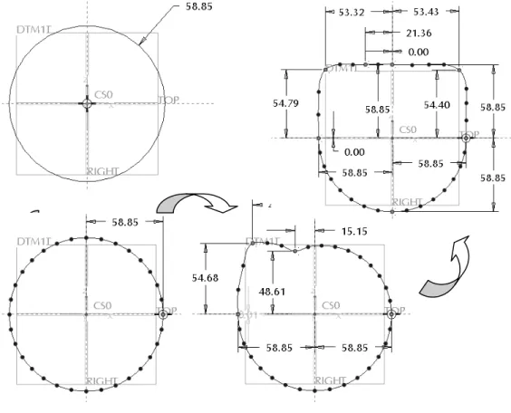
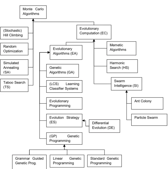
(16) List of Figures Figure 1-1 Splining of a circle for better geometry manipulation. ............................................... 28 Figure 2-1 Perspective view of an engine crankshaft................................................................. 35 Figure 2-2 Front view of an engine crankshaft ........................................................................... 35 Figure 2-3 Crankshaft from Original V-Six Engine General Motors Corporation......................... 36 Figure 2-4 Patent US 7,210,373 B2, May 1, 2007 .................................................................... 37 Figure 2-5 Patent US 7,234,432 B2 June 26, 2007 ................................................................... 38 Figure 2-6 Combustion Engine Crankshaft ................................................................................ 40 Figure 2-7 Types of unbalance: a) static, b) couple unbalance .................................................. 41 Figure 2-8 Imbalance graph from the original crankshaft design ................................................ 44 Figure 3-1 Probabilistic global optimization algorithms .............................................................. 46 Figure 3-2 Standard loop of genetic algorithms ......................................................................... 49 Figure 3-3 Example bridge characteristics. ................................................................................ 57 Figure 3-4 Evolution of bridge optimization ................................................................................ 58 Figure 4-1 Integration of the optimization/innovation algorithm into the development cycle ....... 68 Figure 4-2 Integration of DAKOTA with CAD Software using Java ............................................ 70 Figure 4-3 Integration of DAKOTA with CAD and CAE Software using Java ............................. 73 Figure 5-1 Assembly model of the crankshaft ............................................................................ 76 Figure 5-2 Profile of original counterweight number 2 ................................................................ 77 Figure 5-3 Profile of counterweight number 2 represented by a spline ...................................... 78 Figure 5-4 Spline scheme of a counterweight CW1 ................................................................... 79 Figure 5-5 Driving parameters of a counterweight ..................................................................... 79 Figure 5-6 Counterweights sketched using splines (dark lines). ................................................ 80 Figure 5-7 Orientation of coordinate system .............................................................................. 81 Figure 5-8 Mass properties extracted from CAD model ............................................................. 82 15.
(17) Figure 5-9 Embedded imbalance formulas in the CAD model.................................................... 83 Figure 5-10 Internal Calculation of the imbalance and fitness function in the CAD software ...... 84 Figure 5-11 Curvature of counterweight profile .......................................................................... 85 Figure 5-12 Evolution of the fitness function using VGGA.......................................................... 91 Figure 5-13 First shapes resulting from vgGA optimization ........................................................ 92 Figure 5-14 Generation history of imbalance fitness .................................................................. 93 Figure 5-15 Graph of imbalance on CW1 vs CW9 ..................................................................... 94 Figure 5-16 Representations of the first attempt with the counterweight (dark line). .................. 95 Figure 5-17 Curvature in CW9 profile showing an improved curvature ...................................... 96 Figure 5-18 Distribution between imbalance and second eigen-mode evaluation. ..................... 97 Figure 5-19: Crankshaft shapes after moga evaluation (new profile in dark line) ....................... 98 Figure 5-20 Imbalance graph of best individual from second approach ..................................... 99 Figure 6-1 Initial conditions of the forging simulation. .............................................................. 103 Figure 6-2 Final conditions of simulation with original profile. .................................................. 103 Figure 6-3 Final conditions using a splined profile ................................................................... 104 Figure 6-4 Pareto diagram and the concept of Ideal. ............................................................... 106 Figure 6-5 Graphic representation of inventive “agents” (dark lines). ....................................... 109 Figure 6-6 Representations of the crankshaft´s counterweights (transparent) ......................... 110. 16.
(18) List of Tables. Table 1 Structure of a DAKOTA input file .................................................................................. 63 Table 2 Environment variables required in the set up of J-link ................................................... 87 Table 3 List of files required for the Java program to run ........................................................... 89 Table 4 Comparison of genetic and inventive principles .......................................................... 108. 17.
(19) 18.
(20) Chapter 1 Introduction. The development of products using simulation with computer-aided design and engineering, contributes to the enhancement of an enterprise’s inventive abilities. Even when the newest modeling systems are capable of representing complex physical situations, the optimization algorithms play an important role in the generation of significant improvements. Recently, computers have taken over large parts of the simulation in all fields where prediction of the performance is necessary. As explained by Dawkins [1], simulation is used when there is a difficult decision to make involving unknown quantities in the future. This dissertation deals with the development of a strategy for the optimization and invention of products using evolutionary design strategies, CAD representation, CAE simulation and automated integration of all these elements. A significant part of this research work starts with the parametric shape optimization of products and then continues with the application of elements related to the concept of computer-aided innovation. In this introduction, an explanation is given of the context in which the tasks to optimize designs are formulated and the foundations of the strategy are established. There is a description of how current design optimization techniques are used and how they can be further developed by making use of geometric splines, in combination with genetic algorithms, to achieve a strategy that allows computers to modify the CAD model automatically and provide inventive results. The case study selected to carry out the proposed strategy is an engine crankshaft, manufactured in a closed forge process. Crankshafts are used as case study because: they are one of the most difficult mechanical elements to design due to the complex dynamic relationships among its features. Crankshafts have a relevant impact in the performance of internal combustion engines and its manufacturing is a challenging task. The heart of a crankshaft geometry traditionally consisted on arc-shaped counterweight profiles. These counterweights have to balance the dynamic loads of the whole piston-rod-crank assembly. Additionally the forging process demands that the shape of the counterweights are designed for a better flow of the metal into die cavity and robustness in the balance and dynamic behavior of the crankshaft. The crankshaft is an element with different functionalities (transform movement into rotation, manufacturing) and physical behaviors (natural 19.
(21) frequencies, imbalance); as all these characteristics conflict among each other, it is especially suitable to be the case study. During the development of the dissertation, different software tools were used in order to execute the different tasks involved: CAD modeling, genetic algorithms, CAE simulation and programming in Java. The intended strategy is based on the simulation of different characteristics of a product. Automation of the process is also pursued, through the integration of the different software, in order to evaluate the emerging design alternatives. The aim of the strategy is to find a new way of performing the design process that can reduce the product development cycle and achieve superior performance compared to traditional trial and error strategies. The next section is a sequential introduction of the methods and techniques deployed during the optimization/invention strategy for the development of the engine crankshaft. First, there is an explanation of evolutionary design, which is a defined group of techniques with similarities that can be seen as the starting point for the construction of the proposed method. The general kinds of mechanical optimization, from which the shape optimization approach is selected to be employed in conjunction with geometric splines, are also presented. Next, the state-of-the-art for engine crankshafts design via the analysis of patents is given. At the end of the section, the hypothesis and the objectives of the research in both the development of the strategy, and the solutions for the crankshaft per se are presented.. 1.1 Evolutionary Design A relatively new area of development called evolutionary design [2] has become an object of intensive research. Peter Bentley describes evolutionary design as a process capable of generating designs by changing topologies and shapes. In this way, an intricate design can arise through a slow, gradual improvement process. Evolutionary design has its roots in computer science, design and evolutionary biology. It extends and combines CAD and analysis software, and borrows ideas from natural evolution. Evolutionary Computation to optimize existing designs (i.e. perform detailed design or parametric design) was the first type of evolutionary design to be tackled [3]. Although the exact approach used by developers of such systems varies, typically practitioners of evolutionary optimization usually begin the process with an existing design, and parameterize those parts of the design they feel need improvement. To give a general context of earlier related approaches, a description of the different categories of evolutionary design that have been classified by Bentley: evolutionary optimization, creative evolutionary design and conceptual evolutionary design, will be helpful. Evolutionary optimization places great emphasis on finding solutions as close to the global optimal as possible [4]. Creative evolutionary design is concerned with the generation of novel designs [5]. In conceptual evolutionary design the relationships and arrangements of high-level design concepts are evolved by trying to generate novel preliminary designs. At the conceptual design stage, designers want to know if the lines of thought they follow are worth pursuing. This understanding can be in the form of underlying trends, existing solutions, trade-offs, etc. that 20.
(22) have been addressed by different approaches [6]. Generative (or conceptual) evolutionary designs using computers to generate the designs form and not only a collection of predefined high-level concepts have the advantage of giving greater freedom to the computer. Typically, such systems are free to evolve any form capable of being represented, and the evolution of such forms may well result in the emergence of implicit design concepts. The concept of emergence related to conceptual design is related to the perceptual processes of interpretation and representation that can evolve into a novel design [7]. Evolutionary design mimics the way nature behaves by using evolutionary algorithms that change the forms and topologies of the design object. The biological analogy of such computational methods is based on some elemental rules of the evolution of species. Such rules of evolution state three vital factors for the existence of an evolutionary process: • • •. A reproductive process or replication ability. A selection process based on performance under given life conditions. Capacity of incurring on reproductive errors (replication with variations).. These factors can be used to simulate the biological evolution on a computer. In doing so, the solution set is represented by data in the computer. The algorithms that manipulate data structures use the biological analogy for selection, mutation and recombination. Although the term "simulated evolution" deliberately suggests an analogy with biological evolution, it is understood that the real biological processes are far more complex than any computer simulation, the simulated evolution is only an idealization of certain aspects of a biological system. Biological systems serve as an inspiration, but computers are not able to implement all biological phenomena, that even today has not been completely understood, such as the existence of parasites, which also have served as inspiration for optimization problems [8]. One of the components of evolutionary computation, the genetic algorithm, has shown a great potential for working on several real-world problems to the point of optimization; in reality, however, it is still quite far from realizing a system of matching the human performance, especially in creative applications such as architecture, art, music, and design [9]. The optimization of existing designs is relatively common, with the creation of artistic images and artificial life growing rapidly. Nevertheless, the development of evolutionary design tools is still at an early stage. So far, many genetic algorithms have been used and tested only in design problem solution with small scope. The research and development of design support tools using evolutionary computing technology are still ongoing and have potential for the development of new design technology. The use of evolutionary computation to generate designs has taken place in many fields since the late 1980s. Designers have optimized selected parts of their designs using evolutionary computation. John Holland presented the pioneering formulation of genetic algorithms and described how the evolutionary process in nature can be applied to artificial systems using the genetic algorithm operating on fixed length character strings in Adaptation in Natural and Artificial Systems [10]. In this work, Holland demonstrated that a wide variety of different problems in adaptive systems (including problems from economics, game theory,. 21.
(23) pattern recognition, optimization, and artificial intelligence) are susceptible to reformation in genetic terms so that they can potentially be solved by parallel computation. The use of genetic algorithms combined with 3D CAD packages and CAE simulation tools has proven to be useful for searching the design space for better solutions, but implementing it consumes a great amount of time and computational resources [11]. Current CAD/CAE packages are originally conceived as to mainly facilitate parametric variations of the parts. In cases where shape and/or topological changes of parts or assemblies are required, such changes have to be manually performed. Activities in the design process that are still performed manually instead of with the use of computers include preliminary design [12], the planning of assembly sequences of mechanical parts [13], and others.. 1.2 Optimization of Mechanical Systems The evolution of product development tools has been characterized by various trends, and the analysis of these trends offers useful hints for predicting next generation systems. In mechanical design, optimization tasks are used for structural optimization, which deals with the development of mechanical structures [14]. Optimization of continuous mechanical structures is much employed in industry, for shape and topology and a combination of the two [15]. The optimization of products and processes has been studied since the spread of computers as an aid for seeking “optimal” forms and shapes of product geometry. For example, when minimizing the weight of a mechanical component, restrictions have to be included to guarantee the stability of the structure (ex. stresses or natural frequencies). The objectives of structural optimization are as follows: (a) minimizing stress or weight; maximizing lifespan, stiffness or first natural frequency; (b) any of these under different constrains, such as: maximum deflection, maximum stress, target weight (volume), target stiffness (displacement) and durability. The choice of design variables ranges from geometrical parameters, control points of spline functions [16], position of nodes [17], shell thickness [18], and beam cross-section [19], to angle of fibers from compound materials, etc. As design variable restrictions a designer can have: upper and lower limit of the design variables (fixations, limitations), discrete and continuous. Also symmetrical conditions and constraints for manufacturing conditions (drilling, casting or forging) are also possible. Particularly, two kinds of structural optimization are often used: topology optimization and shape optimization [20]. Topology optimization is used to find the optimal topology of a part by describing an available space for the part using a FE model, while the optimization algorithm helps find an optimal material distribution. Element properties such as density and Young’s modulus from the FE model are changed during the optimization process until an optimal shape is achieved. After defining a topology for a shape optimization problem, a common practice is to use a fixed set of shape variables to describe the design boundaries [21]. The values of the shape variables are then optimized to provide the lightest possible structural member. Topology optimization is used to reach the highest ratio between volume and some geometrical parameters. It determines the 22.
(24) optimal material distribution within a given design space. For example, it takes out the elements under low stress in geometry by modifying the apparent material density, considered as a design variable in a FEM model. A basic FE model is created and analyzed in a design area with given boundary conditions. Commonly, the aims are to maximize stiffness or maximize the natural frequency of a product. The constraints of the design are the following: the fixations, material volume and largest displacement allowed. The design variables are the material density of the elements, which are counted commonly in hundreds of thousands, which means a huge number of design variables. The goal is, given a predefined design domain in the 2D/3D space with structural boundary conditions and load definitions, is to distribute a given mass, which is a given percentage of the initial mass in the domain determined, in such a way that a global measure takes a minimum (maximum) value. This type of topology variation is being analyzed only as a reference and basis for the kind of optimization that is going to be derived in this dissertation. Shape Optimization consists of changing the external borders of a mechanical part [22]. The geometry of the product is defined in terms of surfaces and curve parameters that define the outer boundary of the product, and allows more freedom for manipulation. Here, the topology remains unchanged. The shape of the structure is modified by the node locations of a product modeled with the finite element method (FEM). The aims are to decrease the stress or the volume or maximize the natural frequency. Constrains to the design include fixations and restrictions for displacement of part borders. The design variables of the product for geometric models are length, angle and radii measurements; and for the FE model, node coordinates. After defining a topology for a shape optimization problem, a common practice is to use a fixed set of shape variables to describe the design boundaries [23]. The values of the shape variables are then optimized to provide the lightest possible structural member. Specification of the initial set of shape variables is done while maintaining accurate structural analysis predictions by automating the variable selection process. Another kind of optimization is an advanced form of shape optimization is known as topography, in which, e.g., a distribution of ribs and pattern reinforcements is generated in a specific design region. The approach in topography optimization is similar to the approach used in topology optimization, but shape variables (node coordinates of a FEM model) are used instead of density variables [24]. Other approaches for structural topology optimization present a method based on level set models for optimizing linearly elastic structures which satisfy a design objective and certain constraints. In this method, the structure under optimization is implicitly represented by a moving boundary embedded in a scalar function (the level set function) of a higher dimensionality [25]. Other cases of topology generation—that is, establishing a feasible configuration to meet given functional requirements and size and shape optimization—to meet the prescribed quantitative performance can be found in micromechanics as well [26] Each optimization method uses a strategy to get the optimum of the objective function. The choice of the optimization method and the strategy depends mainly on the properties and number of the variables, the objective functions and constrains, and how these are used in the optimization. Specific criteria for optimization problems include: the number of variables (often many of them); characteristics of the objective function (continuous, discontinuous, linear/ 23.
(25) quadratic/arbitrary, etc.); restrictions characteristics (none, several, etc). Moreover, the external conditions for choosing an optimization method rely on the required accuracy (improvement or exact optimum); efficiency of the algorithm; computing time and memory space; user friendliness and complexity of the problem formulation. Current CAD/CAE packages are conceived to help parametric variations of the parts. In recent years, shape and topological optimization have been introduced into CAD/CAE environments [27]. However, the shapes obtained this way are not structured CAD models and need manual post processing or even redesign to convert them from mesh or neutral geometric models to full CAD models. One of the aims of this research is to further develop the optimization systems mentioned above by adding new concepts to the previous paradigms. In doing so, a different kind of optimization is inferred by taking the characteristics of the last three FEM based types just mentioned. To get a similar behavior (shape, topology and topography) within a CAD model, the geometry of the product is described in terms of splines. The “splining” approach extends these features, allowing the introduction of innovative concepts [28]. This approach is explained further in the next sections. Evolutionary design takes both CAD and CAE, and extends the analysis and detailed design capabilities for which they have been used until now. Moreover, the processing capabilities of computers continue to grow, which makes the resolution of more complex FEM models possible. The possibility of achieving changes of geometric shapes of whole parts and features directly in the context of representation with commercial CAD packages needs new concepts. Tools for facilitating automatic shape variations in parametric 3D CAD environments with the purpose of using genetic and evolutionary algorithms for the shape and topological optimization are presented in this work. The central idea here is that generating creative designs would only be possible by going beyond the bounds of a representation, and by finding novel solutions, which simply could not have been defined by that representation. The concept of Generative CAI Process is derived.. 1.3 Shape Optimization Based on Genetic Algorithms The shape optimization of engineering objects is an important part of the design process [29]. Many different approaches have been adopted in this area, from the homogenization method [30] to the topological derivative method [31]. Shape optimization based on genetic algorithms (GA), or based on evolutionary algorithms (EA) in general, is a relatively new area of research. The foundations of GAs can be found in a few articles published before 1990 [32]. After 1995 many articles on investigation and applications have been published, including a great number of GA-based geometrical boundary shape optimization cases. The interest in research in evolutionary shape optimization techniques has only recently started to grow, including one of the most promising areas for EA-based shape optimization applications: mechanical engineering. Genetic algorithms are a computational tool for the search for optimal design solutions based on the selection of the “fittest”, even when the internal mechanism of the system 24.
(26) under optimization is not well known. Genetic algorithms have been used in different applications; one is the optimization of geometrical shapes, a relatively new area with high potential for research. There are applications for shape determination during the design of machine components and for optimization of functional performance of these components, e.g. antennas [33] [34], turbine blades [35], aircraft geometries [36], etc. Difficult shape optimization problems are common in many other areas as well. In the future, one of the areas with the most potential for EA-based shape optimization applications is mechanical engineering, as designing machine components typically includes shape determination and optimization for functional surfaces of the components. In the field of mechanical engineering, methods for structural and topological optimization based on evolutionary algorithms are used to obtain optimal geometric solutions that were commonly approached only by costly, time consuming iterative processes. For example, a paper published in 2004, reported that an efficient optimum design process was developed and applied to systematically design a lock-up clutch system for a torque converter used in an automatic transmission [37]. A simulated annealing algorithm was applied to find the parameters of the compressive helical damper springs in the clutch. Next, FE-based shape optimization was coded to find the shape of the clutch disk that would satisfy the strength, noise and vibration requirements. Using the optimization algorithm, parametric studies were performed to see how spring diameters and frequencies of clutch systems changed as the damper spring traveling angles and the torques were varied. A genetic algorithm for spring optimization and an FEM-based algorithm for optimizing disk shape were utilized in the project reported in that paper. The shape optimization approach has been also employed to optimize forging preforms using the reverse simulation method. Bramley developed a reverse method in which a preform shape was obtained by reversing the direction of the velocity field to give a minimum value for the overall rate of energy dissipation and which was optimized by the current boundary contact conditions [38]. The approach employs a criterion based on the concept of the material distribution to determine the boundary condition and to evaluate the complexity of the deformed shapes resulting from reverse simulations [39]. Genetic algorithms to optimize existing designs by parameterization was the first type of evolutionary design to be widely used. GAs integrated into CAD and CAE systems are used in parametric and structural optimization to find optimal topologies and shapes of given parts under certain conditions. Advanced CAD and CAE software have their own optimization capabilities, but are often limited to some local search algorithms, so for this dissertation the decision was made to use genetic algorithms. To make such integration, it is necessary to develop an interface to link the GAs to the CAD models and to the CAE analysis. This dissertation presents an approach to this task and some approaches that can be used to construct a strategy on crankshaft design and development. The approach of evolutionary design with splines [20] has the potential to be generative.. 25.
(27) 1.4 The Splining Approach In the mechanical field, geometric parameterization is used to define the kind of changes described by design variables. The geometry of a product keeps its topology but changes in terms of its dimension values or some properties of the structural elements, such as thickness, width and height. Parameterization of the dimensions that describe the product allows optimization based on measures, and is performed through CAD geometric variations. Shape optimization determines the optimal boundaries of a structure for the given fixed topology. Design variables are typically spline control points defining the shape of a structure in 2D or 3D [4]. An efficient way of creating and controlling the form parameters of a given geometry is to convert them into spline models. The spline curve entity is a non-uniform cubic spline, defined by a series of three-dimensional points, tangent vectors at each point, and an array of un-normalized spline parameters at each point. A spline curve is a sequence of curve segments interconnected to form a single continuous curve. Curvature continuity is an important requirement for many applications, and most shapes are simply too complicated to define using a single curve. A Bspline (the most popular spline) is a series of Bezier curves. A Bezier curve always passes through the first and last control points and lies within the convex hull of the control points. A Bspline of degree can be defined with a knot vector. A knot vector is a list of parameter values, or knots, that specify the parameter intervals for the individual Bezier curves that make up a Bspline. A B-spline curve with an evenly spaced knot vector is known as a uniform B-spline. If the knot vector is not evenly spaced, the curve is called a non-uniform B-spline. B-splines are said to have the property of local control, since any given control point can exert influence at most curve segments [40]. A spline is commonly used to define complex geometries that cannot be modeled, or are difficult to model using lines, curves, circles, etc. Shape parameterization is based on different kinds of curves. B-splines [41] are used to define curved profiles. The advantage of these spline geometries is that they have a shape that is easily controllable through control points. Control points are points in space through which a curve must be adjusted. Another characteristic of these curves is the possibility of making special adjustments (like sharp angles), depending on the relative position of the control points. The splines can be applied to define geometry of complex shapes, such as fan wings [42] and also can be used in mesh representation for FEM models [43]. In other words, the parameters of a spline control its shape, so any kind of transformation can be executed. The design of parts in 3D parametric CAD packages is based on sketches of the features that determine the topology of the model´s parts, which are related to each other through different Boolean operations. In the parametric sketches, common basic geometric elements such as lines, polylines, arcs and circles are used. As splines are geometric entities that are very well suited for shape variations, for more complex geometries, splines will be used. The main idea of this approach consists of converting all the basic geometric elements of the sketches that constitute a part, into spline features, whose shape is controllable by manipulating the coordinates of its control points. Splines are used to define curved bodies and profiles. A circle, 26.
(28) for instance, could be easily defined by a spline by placing all of its control points on the circle perimeter. Arcs and straight lines are also easily replaceable for splines. To obtain higher levels of freedom in shape variations, basic geometric features that only allow parametric variations are converted into geometrically equivalent spline models. This operation has been named “splining” [28]. The increased flexibility derived from the splining approach [44] could suggest a very high number of variation possibilities for a given part, including different shapes for features; even though genetic algorithms are being studied for their ability to decide automatically the bestsuited modification for a given purpose, there are many initial possibilities. The “splining” approach for optimizing designs using GAs is relatively new. It has been used, for example, for data fitting using genetic algorithms [45]. Practitioners of evolutionary optimization using splines commonly start the process with an existing design, substitute the current construction with splines, as the number of degrees of freedom can be increased at will by adding control points, and then parameterize the control points of the splines that embody those parts of the design they feel need improvement. The control points are encoded as genes, and the alleles (values) from which the parameters are described are evolved by an evolutionary search algorithm, e.g. Genetic Algorithms. In the field of mechanical engineering, this approach has been applied to the computer design and optimization of the profile shape of a cam for a diesel engine [16]. The goal of the cam optimization was to optimize the movement of the system. That article describes a genetic algorithm with a computer-aided approach for preliminary design and shape optimization of cam splined profiles for cam-operated mechanisms. The primary aim of the project was to create a complete systematic approach for preliminary cam shape design including design automation and true cam shape optimization with respect to the simulated computer models of cam mechanisms. Shape optimization of a cam cross-section is a multiobjective optimization problem of a two-dimensional geometric splined shape in a constrained environment. The conclusions of the article are that with genetic algorithms it is not only possible to design and optimize geometric shapes, but also to develop procedures and tools to automate the design process and get the best form simulation software better and more effectively than what an experienced person could do by trial and error. Splining may constitute a basis for allowing crossbreeding of different geometries, as the points of the splines may be used as “genes” from the parents that transmit their properties to their offspring. Geometric crossbreeding should be done at the sketch level of the construction features of the parts’ geometry. The possibility of crossbreeding two or more parts or assemblies perhaps would need to first, recognize when two different parts are able to generate an offspring, or when two different assemblies generate a new assembly. At feature level, the crossbreeding is possible between two different geometries of sketched features, see Figure 1-1. However, at the part level some similitude inside the tree of the parts’ features should be present to allow two different parts to crossbreed. The same may be true for crossbreeding two different assemblies; i.e., some similitude of the assembled structure could be required for achieving a “successful” crossbreed of two assemblies or subassemblies. 27.
(29) Sketches are controlled through its parametric structure, which changes during the splining approach. A solution is found for substituting the initial parametric structure with a new controlling structure that allows parametric similar control of the size of parts and features being analyzed. This solution is accomplished through the control points of the spline. Even though the focus on the splining technique is about shape variations that allow the persistence of CAD models, there are other interesting ways of obtaining these same advantages by developing special shape variations at mesh level and then translating them into direct change for a previously “splinized” CAD feature. For this purpose mesh morphing in existing commercial finite element meshing software exists, which allow shape variations to be made in a mesh model without remeshing it.. Figure 1-1 Splining of a circle for better geometry manipulation.. The designs are often judged by making an interface of the system to simulation software or analysis software, which is used to obtain a fitness measure for each design. These tools result in an extended optimization method, achieved by representing shapes with splined curves [11]. This eliminates non-parametric dependency on FEM and allows a concept variation of forms. Automatic variations in shapes are produced by the computer and concept variations are evaluated by analysis software. 28.
(30) 1.5 Justification, Hypothesis and Objectives Structural optimization has achieved a level of development that makes it possible to go beyond the current limits of optimizing shapes of parts. This kind of optimization also allows designers to improve the traditional design process, helping them to make decisions regarding new innovative shapes and solutions that arise during the shape variation and simulation process. Designers can now take advantage of not only using parametric CAD models to analyze the influence of geometric parameters variations, but also the effect of shape variations on the required performance of their designs. This thesis presents a strategy that allows the designer to perform an automatic search process for crankshaft design objectives based on genetic algorithms, integrated with the simulation of crankshaft behavior with respect to its balancing and torsion vibrations. At the same time, it looks for an optimal forging process, one that allows improve the crankshaft design process, compared to the design approaches used until now. An important characteristic of the strategy presented in this thesis is the automation of the search process, as genetic algorithms through crossbreeding and mutations of the counterweight profile control the variation of shapes in search for the target balance. At the same time, seek to achieve a target position of the crankshaft’s center of gravity and achieving an optimally forgeable shape.. 1.5.1. Justification of the research. The motivation for the development of this effort is to contribute to the forging industry by the use of the breakthrough optimization techniques, which improves the design of new products. The intention is also to bring to the world of technology research on the use of evolutionary techniques in a mechanical design problem as the forging design of a crankshaft is. An opportunity has been detected to carry out the research using an industry-academia approach. Eight years of experience in Forja de Monterrey have made the author acknowledge needs that can only be addressed by this kind of project to achieve improvement benefitting the country, the industry and the academy research. The next following two quotes express the perceived trend in the industry motivating this research dissertation: “In the year 2020, forging will be the cost-effective, preferred process by which metal components of superior quality, integrity, and performance are produced for critical and demanding applications.” (Technology Initiative, Forging Industry Association, 2002. http://www.forging.org/ techno/Vision.htm#execsum) “To maintain the main development thrusts of the forging user industries, forging companies need to enhance their take-up of new technology and in particular the use of modeling techniques for part and process design”. (Modeling tools for the forging industry - FORGE-NET. The European Commission. http://europa.eu.int/comm/research/brite-eu/thematic/html/1-107.html) 29.
(31) Optimization is a design activity where the mean is shifted to target and reduce the variability for all the responses [46]. Optimization is used to take a particular design and improve it to a level of superior performance, but once this level has been achieved, further improvement is impossible through the use of the same optimization tools because the best combination of parameters in the design has been found. In some cases, the way designers formulate their problems can lead to excessive assumptions, engineering approximations, and restrictions, with which an optimum design is created, but in a sense that it is the only feasible design, not the best solution. To overcome this apparent contradiction, this research proposes a process that integrates shape variations and supports the use of interesting optimization approaches, e.g. genetic algorithms. All of this takes place in an automated environment with the ultimate goal of using computers to help designers to overcome design fixation when developing a product. And then, due to this combination of factors, inventive solutions may arise by the emergence of ideas from the stimulated mind of the designer, which can be then regarded as generative computer aided invention. From the last, the research is intended to prove the next:. 1.5.2. Hypothesis. The integration of 3D-CAD parametric models, adaptive splinization, CAE analysis and genetic algorithms, by means of the deployment of tasks that automate the design process, improves the performance and manufacturability of engine crankshafts. The achievement of novel responses that emerge during the genetic evolution process can lead to new generative computer aided inventive solutions that help overcome design fixation. The optimization capabilities of computers can be extended, when introducing elements of inventive methodologies, in a way that makes them an innovation tool for designers. This will allow them to get the best from simulation software, and reach novel solutions during product development of crankshafts more efficiently than by the trial and error method.. For the demonstration of the hypothesis, the research was conducted within the following:. 1.5.3. Objectives. a) The development of a strategy that combines the activities of concept generation and evaluation; and merges them in a loop inside the product development process, in order to improve the design of a crankshaft. The strategy aims to integrate the loop into a computer aided invention framework, and by doing so, extend the optimization capabilities of computers to provide inventive results. b) The generation of novel designs of the case study of an engine crankshaft, in order to obtain an inventive solution that represents an improvement of the crankshaft, in terms of 30.
(32) imbalance, dynamic response and manufacturability. By using the genetic algorithms for spline manipulation, it is possible to monitor the progresses of the shape construction as real-time identification of design trends and make changes to the definition of the shapes. Under those objectives, the research is aimed to improve the traditional design process to become a computer aided invention process. Designers can take advantage of the methods and make use of parametric CAD models available during the product development process to analyze the influence of geometrical variations. An important characteristic of the tasks presented in this thesis is the automation of the optimization/innovation process. From the geometric model modifications to the evaluation of the analyses, modern CAD software and optimization tools meet all the requirements for such evolution.. 1.6. Conducted methodology for the completion of the research. The methodology conducted in order to reach the objectives and for instance, demonstrate the hypothesis, consisted of the following steps. A) Problem statement. It is analyzed the functioning of crankshafts and its geometrical construction. The shapes that are going to be converted to splines are selected and it is decided over the set of parameters to be controlled. B) Literature review. It is conducted a literature review of the methods and tools that have been used in previous approaches. The elements of those methods that have the necessary conditions for integration are selected to be used in the research. C) Development of the strategy. The computer aided invention strategy is development with the elements selected but integrated by a set of tasks. Those tasks are defined by the kind of optimization that is pursued. D) Deployment of the implementation. The strategy and particularly the set of tasks are implemented into the case study of the crankshafts. The results of the improvement of the crankshaft in terms of performance are obtained. E) Construction of the theoretical foundations. The basis of a computer aided invention strategy are presented. The fundamentals of a framework to extend the product development cycle into an innovation approach are explaided. The previous steps of the methodology for the completion of the dissertation are presented and explained in the following order of chapters. Chapter 2 states and explains the problem of optimizing an engine crankshaft. The case study selected and how the CAD modeling of the crankshaft is made using splines are presented. A brief introduction to the dynamics of a crankshaft, and the imbalance and its importance during the manufacturing process are included. The chapter describes the equations of imbalance and the initial measurement to be used as reference for the improvement during the development of solutions. 31.
(33) Chapter 3 offers a review of the literature, focusing on general optimization methods and, particularly, on genetic algorithms. It is explained why a stochastic technique as the geometric algorithms are necessary in the research. The multi-objective optimization strategies and why the case study was considered suitable for multi-objective analysis are also discussed. The concept of Pareto frontier is explained and how the Pareto graph can be used to reveal conflicts in performance parameters of a system. A description is given of the optimization software DAKOTA and its code structure. Chapter 4 present the overall strategy developed for extending the optimization paradigm into an innovation framework, and a description of the different tasks that are integrate. The first task consists of the optimization of the imbalance of the crankshaft, taking into consideration only geometric modifications of the CAD model. The second task extends the use of CAE tools to analyze the dynamic behavior of the crankshaft by measuring, together with the imbalance, the eigen-frequencies of the crankshaft. Chapter 5 describes the deployment of the tasks, with the case study of the crankshaft, introduced in chapter 4 and presents the results obtained from each. It is made a detailed description of the geometry substitution by spline curves of the counterweights. It is explained the construction of the CAD model and the introduction of the imbalance formulas inside the CAD model thanks to the software functionality. It is described how the optimization loops are built to have the different software integrated via programming in Java. The results of the tasks are presented in the form of modified crankshaft geometries. Chapter 6 gives a general description of the optimization/innovation approach. A proof of concept of the results from chapter 5 is performed using simulation of the forging process. It is presented a reflection of how the strategies are more than an optimization approach and extend the optimization capabilities of computers. It is explained how the combination of tools allow to conduct an innovative solution by overcoming conflicts in a multiobjective problem. It is also presented the ideas relating the TRIZ integration with Genetic Algorithms. Chapter 7 contains the conclusions and future work that can be derived from the research that is developed in this dissertation.. 32.
(34) Chapter 2 Problem Statement The case study was selected in view of the importance of motor crankshafts in the automotive industry [47] and the increased performance requirements for engines, which have raised the production of forged steel crankshafts worldwide. The auto industry will continue to move toward forged crankshafts, as engines become more fuel-efficient, producing more horsepower per liter. During the late 1970s, designers recognized that the need for greater fuel economy would be driving up the engine horsepower per liter through greater compression ratios and much higher rpms. Since roughly the mid-1980s it has been recognized that to achieve those goals, designs would have to be changed to achieve stronger crankshafts. Particularly, the development of engine crankshafts is subject to a continuous evolution due to market pressures. Fast market developments push the increase of power, fuel economy, durability and reliability of combustion engines, and call for reduction of size, weight, vibration and noise, cost, etc. Optimized engine components are, therefore, required if competitive designs are to be attained. Given these conditions, crankshafts, which are one of the most analyzed engine components, must be improved [47]. For crankshaft material, the choices were largely between austempered ductile iron (ADI) and forged steel. Since the low-cost nodular iron would now have to change to a heattreated product cast from a special grade, the economics of castings were not as positive in comparison with forgings. Furthermore, the advent of micro alloy steels allowed forge shops to compete effectively with ADI because micro alloys can be used to eliminate the heat treating cycles for forgings [48]. An important direction in improvement trends is the optimization of its geometrical characteristics. In particular for this paper, imbalance, first Eigen-frequency and the forge-ability are the optimization objectives. Analytical tools can greatly enhance an understanding of the physical phenomena associated with the above mentioned characteristics and can be automated to do programmed tasks that an engineer requires for optimizing a design [2]. Imbalance, one of the quality parameters of crankshafts, has a significant impact on the life of the entire system. In the forging process, given the variations of material composition, temperature, etc., the imbalance dispersion increases compared to the casting of crankshafts. It is of particular importance to reduce this variation right from the conceptual design of the crankshaft [49] [50]. As the crankshaft is an element with different functionalities (transform linear movement into rotation, manufacturing) and physical behaviors (natural frequencies, imbalance) it is especially suitable to be case study for an optimization problem. Crankshafts have performance parameters and restrictions that are commonly analyzed and studied, with software tools, during the design and development process of an engine. These performance parameters are to be optimized (minimized or maximized) by making variations in the geometry. The selected goal of the crankshaft design study for this research is to reach the imbalance target and reduce its weight and/or increase its first Eigen-frequency. The design of the crankshaft is inherently a multi-objective optimization (MO) problem. The imbalance is measured in both sides of the crankshaft so the problem is to optimize the components of a vector-valued 33.
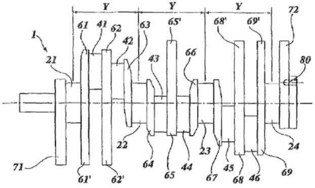
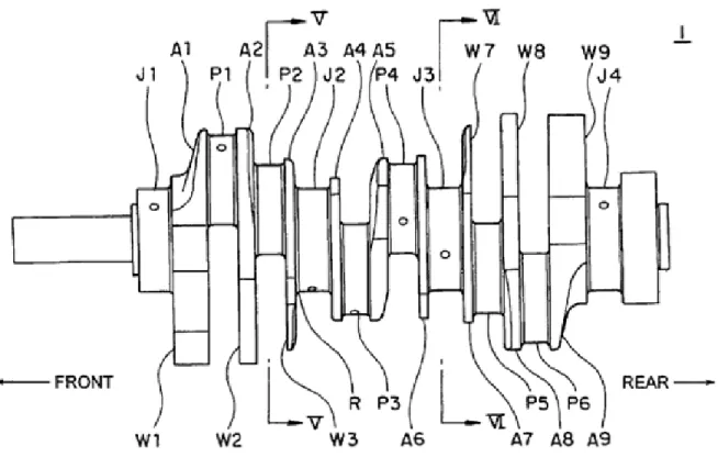
(35) objective function consisting of both imbalances [51]. Unlike the single-objective optimization, the solution to this problem is not a single point, but a family of points known as the Paretooptimal set. Each point in this set is optimal in the sense that no improvement can be achieved in one objective component that does not lead to degradation in any of the remaining components [36]. The objective functions of imbalance are also non-linear. Auxiliary information, like the derivatives of the objective function, is not available. The fitness-function is available only in the form of a computer model of the crankshaft, not in analytical form. Since the approach required taking the objective function as a black box, and only the availability of the objective function value could be guaranteed, no further assumptions were considered. Thus, the only realistic alternative was applying a stochastic global optimization approach. Since GAs have already widely demonstrated capabilities for effective, efficient and robust global optimization in cases for many black-box type computer models, including many shape optimization models, GAs were considered the most attractive alternative for the research purposes. The Paretobased optimization method, known as the Multiple Objective Genetic Algorithm (MOGA) [52], is used in the present MO problem, to find the Pareto front between these two fitness functions.. 2.1 State-of-the-Art in Crankshafts A crankshaft used in a V-type six-cylinder engine is equipped with six crank pins (numbered P1 to P6, see Figure 2-1), four crank journals (numbered J1 to J4), and nine arms (numbered A1 to A9) for connecting the crank pins and the crank journals to each other. Some of these arms are each equipped with a counterweight (numbered W1 to W9) to reduce the rotational force of inertia generated in each arm and the unbalance couple generated in the crankshaft. A1. P1 A2. W4. A5 P4. A3. A6. FRONT W1. J3 W7. W8 W9. W2. J4. W3 J2 P3 A4 W5 W6. A7. P5. A8 P6. 34. A9. REAR.
(36) Figure 2-1 Perspective view of an engine crankshaft. In a conventional crankshaft, the counterweights are situated in a direction completely opposite the crank pins connected to the arms with respect to the central axis of the crankshaft. That is, in the case of an arm to which only one crank pin is connected, the counterweight is situated in a direction completely opposite that crank pin (see Figure 2-2). In the case of an arm to which two crank pins are connected, the counterweight is situated in a direction completely opposite the midpoint of the two crank pins.. P1 P2. P4. P3. P 5 W1. P6. Figure 2-2 Front view of an engine crankshaft. In a review of the history of the development of V6 type crankshafts, an exhaustive patent search was conducted. The original V-6 Engine can be found in a patent [53] from the former General Motors Corporation. The text of the patent is very descriptive with respect to the intention and goals of the research: “The present invention relates to internal combustion engines, and more particularly relates to the crankpin arrangement and balancing means for a 60° V-6 engine. “Modern automotive internal combustion engines are required to operate at high speed with a minimum of vibration. This requirement necessitates accurate and complete balancing of the inertia forces and couples set up by rotating and reciprocating masses within the engine. “V-6 engines are rigid and compact and are therefore desirable as automotive power plants. The lack of a suitable crankshaft design and balancing means for these engines has delayed their adoption by the automotive industry. It is well-known that if the forces and couples of an engine are not balanced, excessive vibration will result. This vibration greatly increases the wear on engine parts, and passenger discomfort and reduces the life of the engine. For these reasons, it is necessary to reduce engine unbalance to a minimum. 35.
(37) “Engines may be out of balance, with resulting vibration and excessive wear, due to either unbalanced forces or unbalanced couples. The unbalance forces may be "primary" or those operating at engine speed or may be higher order forces which are classified as a "secondary," "tertiary," etc. corresponding to the harmonic of engine speed at which they are effective. The term "unbalance couple" as applied here, is the product of the force times the distance the force acts from a preselected datum line. These couples may be either so-called "shaking" couples which are manifest by forces acting in a single plane lying in the longitudinal axis of the engine or they may be rotating couples which change their direction of application with respect to the line of center of the engine either at engine speed or at some harmonic thereof. The design of the present engine eliminates all shaking couples. The unbalance, due to rotating forces resulting in rotating couples of higher order than secondary, are negligible in the present engine. The primary unbalance forces and rotating couples are counterbalanced by the use of weights located on the engine crankshaft and fly-wheel.” See Figure 2-3.. Figure 2-3 Crankshaft from Original V-Six Engine General Motors Corporation.. In the patent databases, the older the patent, the simpler the counterweight’s profiles; crankshafts are modeled with the use of arcs and particularly the use of symmetry. It means that newer crankshafts are less symmetric, in order to adapt to the balance, but still use simple arcs. A patent from 1985 [54] provides the crankshaft with two more counterweighs than the original crankshaft, which consisted of counterweighs in the extreme sides. The crankshafts then have counterweights in the first, second, eighth and ninth arms. A patent from 1988 [55] claims to provide an excellent engine crankshaft structure which is useful in the drive system field in the automotive industry. It uses the conventional crankshaft structure that it can well afford to bear large surface pressure and to resist a large bending and shearing stress and by minimizing the number of counterweights. Patent from 1996 [56] presents a crankshaft of a V-type 6-cylinder internal combustion engine which claims to ensure a decrease of the engine vibration and surface pressure affecting each crank journal by achieving effectively dynamic balance of a 36.
(38) whole crankshaft and dynamic balance couple between inner main bearings with an optimum size of balance weight. A patent from 1998 [57] involves a crankshaft in which counterweights are provided respectively on only the first, second, fifth, eighth and ninth arms, with the weight and thickness of the first to fifth counterweights being set to predetermined values respectively. The next two patents are the newer regarding V-type 6 cylinder engines. A 2007 patent [58] is an invention to provide a crankshaft for a V-type internal combustion engine of the type with a pair of counterweights arranged outwardly of the axially outermost journals. The crankshaft includes a first to a sixth crank pin, a first to a fourth main journal and a first to a ninth crank arm. At least the first, the second, the eighth and the ninth crank arms have respective integral counterweights for balancing the crankshaft. To reduce bending stress on the areas where the second and the eighth crank arms are connected to the respective pairs of adjacent crank pins (bending problems particularly present in the forging dies during the manufacturing process), the axial dimensions of the first and the ninth crank arms are reduced. Being substantially the same as those of the adjacent crank arms (second and eight); in order that the axial length of the two end spans of the crankshaft is the same as that of the intermediate span. In order to set the balance of the crankshaft back to the original value, two additional counterweights are arranged outwardly of the end journals and their axial dimensions are comparable to those of the end crank arms, see Figure 2-4.. Figure 2-4 Patent US. 7,210,373 B2, May 1, 2007. Another patent granted in 2007 [59] is for an invention to provide a crankshaft for a V-type sixcylinder engine capable of reducing the generated unbalance couple to a sufficient degree. Thus, in the crankshaft the arm A5 has no counterweight, which makes it possible to achieve a 37.
(39) reduction in weight. Without counterweight 5 the effect of reducing the bearing load generated in the crank journals J2 and J3 through the rotational force of inertia of the crank pins P3 and P4 is lower than that in a case of a crankshaft in which the arm A5 has a counterweight. Accordingly, in the crankshaft 1, which is for use in a diesel engine, there is practically no disadvantage in increasing the bearing load due to the fact that the arm A5 has no counterweight, making it possible to attain, substantially and exclusively, compatibility between a reduction in weight and a reduction in unbalance couple. Furthermore, arms A1 through A3 and the arms A7 through A9 respectively with counterweights, are concentrated on both ends of the crankshaft. So that if the total weight is the same as that of a construction in which counterweights are provided on arms near the center (e.g., a construction in which each of the arms A1, A2, A4, A6, A8, and A9 has a counterweight), a moment generated is larger. Whereby it is possible to more efficiently achieve a reduction in unbalance couple. See Figure 2-5.. Figure 2-5 Patent US. 7,234,432 B2 June 26, 2007. A patent from 2001 [60] describes a crankshaft not for a V6 engine, but rather for a forged crankshaft for an internal combustion engine, and more particularly to a crankshaft with larger counter weights, but which does not cause interference between the counter weights and neighboring parts of the engine. According to one aspect of the invention, an engine crankshaft with at least one counter weight made by forging is provided. As the forging being performed by pressing two dies to each other, it is characterized by the fact that the counterweight has a plurality of inclinations to facilitate removal of the dies from the crankshaft after the forging process is completed. The degree of inclination of the plurality of inclinations is reduced since 38.
Figure

+7


Documento similar
We will extend the existing theory of methods of moments to learn models that are traditionally used to do topic modeling – like the single-topic model and Latent Dirichlet Allocation
No obstante, como esta enfermedad afecta a cada persona de manera diferente, no todas las opciones de cuidado y tratamiento pueden ser apropiadas para cada individuo.. La forma
Derivative of such analysis and based on the need of obtaining simple methods which are able to operate in heterogeneous envi- ronments at different speeds, a fast packet
Three sample treatment methods, based on QuEChERS, solid-phase extraction (SPE) and solid-phase microextraction (SPME), were compared and evaluated in order to obtain the
In chapter 3, the overview and challenges of integrative –omics analysis and the main statistical methods that have been used for data integration is described and in chapter
To put Theorem 2.1 into perspective, recall that there exist analogous structure results for cohomogeneity one actions on closed smooth manifolds, on closed topological manifolds and
To create genetic graph-based clustering algorithms and heuristics to improve the robustness and solutions of classical partitional clustering algorithms, and to study its
We have stud- ied the relation between higher-order Lagrangian systems with constraints (nonholonomics and vakonomics) and higher-order Hamiltonian systems, the reduction by
