SYNTHESIS OF MULTIRESOLUTION SCENES WITH GLOBAL
ILLUMINATION ON A GPU
Raquel Concheiro
1, Margarita Amor
1, Montserrat B´oo
2, Iago Iglesias
1, Emilio J. Padr´on
1and Ram´on
Doallo
11Dept. Electronics and Systems, Univ. Coru˜na, E–15071 A Coru˜na, Spain
[email protected], [email protected], [email protected], [email protected], [email protected]
2Dept. Electronic and Comp. Eng., Univ. Santiago de Compostela, E–15782 Santiago de Compostela, Spain
Keywords: Multiresolution:GPU:Radiosity:Subdivision Surface
Abstract: The radiosity computation has the important feature of producing view independent results, but these results are mesh dependent and, in consequence, are attached to a specific level of detail in the input mesh. Therefore, rendering at iterative frame rates would benefit from the utilization of multiresolution models. In this paper we focus on the rendering stage of a solution for hierarchical radiosity for multiresolution systems. This method is based on the application of an enriched hierarchical radiosity algorithm to an input scene with low resolution objects (represented by coarse meshes), and the efficient data management of the resulting values. The proposed encoding makes it possible to apply the color values obtained for the coarse objects to detailed versions of these objects during the rendering phase. These finer meshes are obtained by a standard mesh subdivision strategy, such as the Loop subdivision scheme. Our solution performs the whole rendering stage of this multiresolution approach on the GPU, implementing it in the geometry shader using Microsoft HLSL. Results of our implementation show an important reduction in computational costs.
1
INTRODUCTION
Realistic scene walkthroughs are commonly per-formed in many applications such as virtual reality, simulations, animation, games or geographic infor-mation system. Global illumination models, such as the hierarchical radiosity algorithm (Hanrahan et al., 1991), are usually needed to achieve realistic illumi-nation results. Radiosity is view independent, so the results obtained can be re-employed for camera walk-throughs of the scene. An important drawback, how-ever, is the mesh dependence of the radiosity compu-tation that, in consequence, results in obtaining illu-mination values attached to a specific level of detail in the input mesh. Due to this fact, the obvious approach to get optimum results could be using a very detailed input mesh but, unfortunately, that means high putational costs. Thus, real time rendering of com-plex scenes would benefit from the utilization of mul-tiresolution models. This could imply radiosity re-computation after each change in the object resolution level when the camera position changes.
Most of the existing approaches to the use of
mul-tiresolution models in a radiosity engine (Garland et al., 2001; Gobbetti et al., 2003) are based on the re-computation of the radiosity values in terms of the selected resolution of the objects. A proposal that dif-fers from this scheme is presented in (Padr´on et al., 2010). In that work the illumination values are pre-computed only once, using the hierarchical radiosity method, and the challenge lies in the application of the fixed colors computed to a multiresolution scene. The different multiresolution meshes are obtained by a standard mesh subdivision strategy, specifically the Loop subdivision scheme in this case (Loop, 1987).
COARSE MESH COARSE MESH COARSE MESH
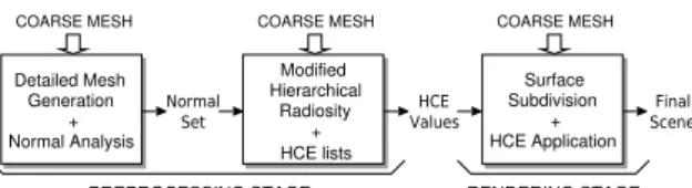
Figure 1: Scheme of a multiresolution radiosity algorithm.
a data structure and breadth-first algorithm to perform recursive subdivision of Catmull-Clark on a GPU us-ing CUDA, is presented.
In this paper we take the proposal in (Padr´on et al., 2010) as a starting point and present an implementa-tion that performs the whole rendering stage of this multiresolution approach on the GPU. This phase ba-sically consists of two steps, first a surface subdivi-sion step and, subsequently, the mapping of colors obtained from coarse meshes of the objects in the scene to more detailed versions of those objects. Both steps are implemented in the geometry shader using the API DirectX 10, with the shaders programmed with Microsoft HLSL. A variant version of the origi-nal Loop subdivision scheme, based on a factored ap-proach (Warren and Schaefer, 2004), has been used as it is more appropriate for an efficient implementation on a GPU. Additionally, an analysis of the different alternatives to access the necessary neighboring in-formation is included in this work.
2
HIERARCHICAL RADIOSITY
FOR MULTIRESOLUTION
SYSTEMS
In (Padr´on et al., 2010), the global illumination computation for a synthetic scene with multiresolu-tion objects is performed using the coarse mesh of these objects. Thus, the colors are precomputed only once, using an enriched version of the hierarchical ra-diosity method to obtain a set of significant pairs nor-mal vector-color per polygon. Subsequently, the main challenge consist in the application of the precom-puted colors to the finer meshes of these multireso-lution objects. The basic structure of this approach is outlined in Figure 1. The algorithm comprises three main stages, two of them associated with the radiosity computation (preprocessing), and the last one dealing with the final mesh representation (rendering).
The developed solution is based on the analysis of the normal vectors of the multiresolution mesh and the selection of a representative set of normals (first preprocessing stage). This set is employed to en-rich the hierarchical radiosity algorithm, thus obtain-ing a set of radiosity values per triangle in the coarse
mesh of a multiresolution object (second preprocess-ing stage). These view independent values are effi-ciently stored and selectively applied to the multires-olution mesh during the last step (rendering stage). The proposed encoding, named Hierarchical Color Encoding method (HCE), allows the direct assign-ment of colors to meshes with any resolution. Note that these computed energy values can be applied to the objects in the scene in any resolution configura-tion, so high quality scenes with very low computa-tion requirements can be obtained.
The mesh detail level of the multiresolution ob-jects in the final render depends on the camera po-sition and computational cost constraints. This mul-tiresolution scheme is based on a standard mesh sub-division strategy. Among all standard subdivision strategies, theLoopsubdivision scheme (Loop, 1987) has been used, although the extension for working with other subdivision schemes is straightforward. Once the mesh is conveniently refined, the radiosity values are applied according to the HCE representa-tion and a given normal selecrepresenta-tion criterion specified.
HCE is a representation method that defines a hierarchical color triangle structure that stores the values obtained from the hierarchical radiosity algo-rithm. The encoding is based on the following struc-ture:ei [TiLiCiRi], whereeiis the triangle color,
fol-lowed by four bits, enclosed in brackets in our nota-tion. Each of these bits is associated with each one of the four child subtriangles (Top,Left,Center,Right). A value of 1 means that the subtriangle is in turn sub-divided into four children, as a consequence of having been further subdivided during the hierarchical refine-ment procedure, also coded in the HCE structure. A value of 0 marks that child as a leaf element.
With this notation, the adaptive subdivision hierar-chy for any coarse triangle can be represented in a list
J, taking the information associated with each level in the hierarchy in a breadth-first way (each subdivision level is listed before starting the next level). To deal with the set of normal vectors per root triangle and the radiosity values associated with them obtained from the global illumination step, the resulting HCE list for a triangleiwith normal~n0i and an additional set of mnormals (Ni={~ni1,~n2i, . . . ,~nmi }) would have the
following structure:
J=s m NiE0 [T0L0C0R0] E1 [T1L1C1R1]. . .
where Ei is the set of m+1 colors (Ei = {e0i,e1i, . . . ,emi }) computed for each triangle in the hi-erarchy for each normal vector. The starting bit,s, is added to mark the root triangle as a leaf (s=0) when necessary (s=1 means there are child triangles).
corresponding model generated, the assignment of colors is performed. A set of colors was computed per subtriangle and listed in theJlist, each one asso-ciated with a representative normal. When rendering, the final color to be assigned to the triangle is based on a normal comparison criterion. Specifically, ifm+1 colors were obtained with the radiosity procedure for a trianglei, the correct color (eki ∈Ei,0≤k≤m)
as-signed to a triangle jin the final mesh is the one with the closest normal vectornki
~nki·~n0j≤~nli·~n0j, l∈ {0...m}
where~n0jis the normal vector of triangle j.
3
SURFACE SUBDIVISION AND
COLOR APPLICATION ON A
GPU USING THE GEOMETRY
SHADER
This section describes the GPU implementation developed for the rendering step of the multiresolu-tion method depicted in Secmultiresolu-tion 2. This last stage of the method dynamically selects the geometric level of detail of each multiresolution object to be rendered as a function of the viewpoint and the associated compu-tational costs. The refined mesh for the selected level of detail is computed by applying the Loop subdivi-sion scheme to the coarse mesh. Afterwards, the ap-propriate colors obtained from the global illumination step are assigned.
We have implemented both the two tasks involved in this phase, surface subdivision and color mapping, in a kernel for the geometry shader. This kernel is spawned for each triangle in the input mesh and per-forms the whole computation (both tasks) for that triangle. Notice that our proposal is recomputation-based, so many redundant computations are made due to the geometry shader constraint that prevent the syn-chronization among tasks. The redundant computa-tions allows multiple arbitrary asynchronous kernel calls and does not affect performance, however. The details of our proposal are detailed below.
3.1
Geometry Shader HLSL
Implementation of Surface
Subdivision with Loop
Our implementation of subdivision using Loop fol-lows the factored approach introduced in (Warren and Schaefer, 2004). This approach deals with all the ver-tices in the mesh, the new ones introduced with the
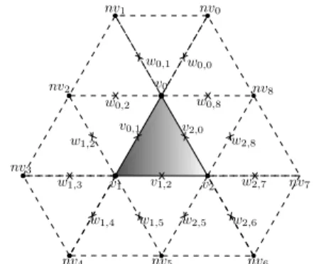
Figure 2: First step in kernel:Linear Subdivision.
subdivision of the edges and the old ones, in a simi-lar way. This feature simplifies the original Loop al-gorithm, avoiding computations and, more important, branch divergence, common performance killer for computations on GPU kernels. To minimize the num-ber of times the subdivision kernel is called in the ge-ometry shader, and to keep the number of output trian-gles below the recommended 25 (Lorenz and D¨ollner, 2008) as well, we have unrolled a couple of iterations of the subdivision iterative process in our implemen-tation. Of course, more iterations of the subdivision process may be computed by sending back the results to the pipeline through stream out.
Each input triangle to be subdivided by the ker-nel, being its three vertices{v0,v1,v2}(see Figure 2)
needs information about the adjacent triangles shar-ing a vertex with it, that is, the rest of triangles with vertices{v0,nv0,v1},{v1,nv1,v2}and so on. A
regu-lar vertex is shared by six triangles (valence 6), so a regular case like the one in the figure needs the geom-etry data of 12 adjacent triangles. The notation used isvifor the vertices in the triangle to be subdivided,
nvjfor neighboring vertices andwkfor the additional
newly created vertices needed for the computation. Each iteration of the subdivision scheme is sep-arated into three different steps: Linear Subdivision,
AveragingandCorrection Factor. TheLinear subdi-vision step (see Figure 2) creates a new vertex as a result of the linear subdivision of every edge in the original input and the adjacent triangles. Therefore, the new vertices{v0,1,v1,2,v2,0,w0,1,w0,2,w1,2,w1,3, w1,4, w1,5,w2,5, w2,6, w2,7,w2,8, w0,8} are obtained
as a result. Onlyv0,1,v1,2andv2,0are inserted in the
mesh, though. The rest, verticeswi,j, are only used in
the next step, Averaging, and will be recomputed in other kernel executions for triangles{nvi,vi,vj}. The
Averagingstep computes the new positions of the ver-ticesv0,v1,v2,v0,1,v0,2andv0,4, aiming at improving
smoothness, this way:
v0i=1
4vi+ 3 4n
n
∑
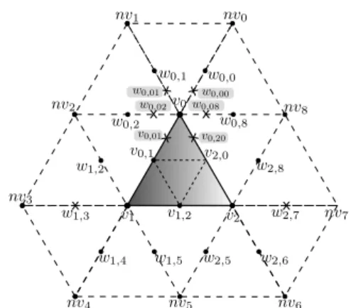
j=1Figure 3: Second iteration in the subdivision process.
wherenis the valence ofvi.
Lastly, a correction factor,c f(n), is applied to the relevant vertices (v0,v1,v2,v0,1,v0,2andv0,4,
follow-ing with the example of Figure 2) to keep the continu-ity of the surface as in the original Loop algorithm (C2
at regular vertices andC1at extraordinary vertices). The new location for these vertices will be:
v00i =vi+c f(n)· v0i−vi.
The correction term is a function of the valence,n:
c f(n) =5
3− 8 3
3
8+ 1
4cos(2π/n)
2
,
so it does not modify regular vertices, that is,v00i =v0i
whenn=6. The terms for each possible value ofn
are precomputed and stored in the constant memory. This read-only memory, optimized for the access to constants, provides a low latency, similar to register.
After the first iteration, 4 new triangles are created and make up the output of the geometry shader if no more iterations are needed. Otherwise, in the second iteration (as commented above, two iterations are un-rolled in our subdivision kernel) 16 new triangles are obtained from those 4 triangles. This second iteration performs again the three steps with the same opera-tions than the previous one. Notice, however, that it is necessary to compute the Averagingand Correc-tion Factor steps of the first iteration for some ver-tices whose computation had not been completed dur-ing the first iteration (because it was not needed). An example is shown in Figure 3: the verticeswi,j(w0,0, w0,1. . . ) were obtained by theLinear Subdivisionstep
at iter. 1, but the other two steps,Averagingand Cor-rection Factor, were only applied on the vertices of the triangle being subdivided (v0,v0,1. . . ). Now, we
need the final (smooth) position of these vertices to get some of the new vertices for the second iteration.
For example, following the example in Figure 3, the smooth position ofw0,1is needed to get the vertex
w0,01as the linear interpolation ofv0−w0,1. Exactly
the same for the rest of the verticeswi,j in the figure
so theAveragingandCorrection Factorsteps are ap-plied to these vertices. These computations in turn imply the computation of additional linear interpola-tions between the verticesnvj. Finally, after updating
the positions of the verticeswi,jthe three steps of the
second iteration can be performed.
3.2
HLSL Implementation of Color
Mapping with HCE
Once the input triangle has been subdivided up to the needed level, the resultant set of triangles has to be rendered. That requires to compute the proper colors for the vertices of these triangles. Since the color val-ues provided by the global illumination phase have been coded for each coarse triangle using the HCE representation, the kernel running in the geometry shader must decode and map the corresponding ra-diosity values to the new triangles and compute the final color value in the vertices. Therefore, this is a two-step process:
1. First, for each generated triangle the more appro-priate color has to be selected from the HCE rep-resentation. This color is the color associated with the more similar vector to the normal vector of the sub-triangle among a set of normal vectors asso-ciated with the original parent triangle.
2. Once the color of all the sub-triangles has been obtained, the color of every vertex is computed as a weighted average of the colors of the trian-gles it belongs to. Naturally, besides the colors of the sub-triangles obtained from the input triangle, the colors of the sub-triangles resulting from the neighboring triangles are needed as well, so they are recomputed as times as needed.
3.3
Implementation Details
As it has been commented, the geometric data of the neighboring triangles is needed to perform an accu-rate Loop subdivision of a triangle. Specifically, we need to access the position of the vertices in the adja-cent triangles, 12 triangles and 10 vertices in the reg-ular case, as seen in Figure 2 (verticesnv0tonv9).
Listing 1: Geometry shader input and vertex shader output.
1 struct V S _ O U T P U T {
2 float4 v P o s i t i o n : P O S I T I O N 0 ;
3 float3 v N o r m a l : N ORMAL ;
4 float4 vCol or : COLO R0 ;
5 float4 ints : STA TUS ;
6 }
position, normal vector, color and additional informa-tion needed in the kernel (the field namedSTATUS), such as the vertex index, whether it is an inner ver-tex o not, whether it is part of a multiresolution object or not and its valence (number of triangles that vertex belongs to).
As it has been commented, there are recomputa-tion in the three proposed alternatives as every input triangle is assigned to a computational core with no possibility of sharing information among cores.
Neighboring Information in Texture Memory (NITM): This first implementation gets all the neighboring information needed during the kernel computation from the texture memory. All the trian-gles are indexed using thePrimitiveIdgenerated by the system. The signature of the function for the ge-ometry shader is:
void GS ( t r i a n g l e V S _ O U T P U T v [3] , inout
T r i a n g l e S t r e a m < GS_OUTPUT > TriStream , uint
P r i m i t i v e I d : S V _ P R I M I T I V E I D )
Regarding the function prototype, the first param-eter sets an input of 3 vertices of type VS OUTPUT
for the geometry shader. With the primitive type
triangle, this means a triangle{v[0],v[1],v[2]}.
Triangle with Adjacent Structure (TA): The in-formation of the three adjacent triangles that share an edge with the triangle to be subdivided is passed di-rectly to the kernel, using a triangle with an adjacent structure as input. This way, we take advantage of thetriangleadjprimitive of geometry shader, that makes this adjacent information directly accessible in the kernel. Rest of the neighboring data is still ac-cessed through the texture memory. Now the function has this prototype:
void GS (triangleadj V S _ O U T P U T v [6] , inout
T r i a n g l e S t r e a m < GS_OUTPUT > TriStream , uint
P r i m i t i v e I d : S V _ P R I M I T I V E I D )
Therefore, the first parameter sets now an input of 6 vertices. As the primitive type triangleadj
indicates, these vertices are interpreted as a triangle
{v[0],v[1],v[2]}and three adjacent vertices.
(a) (b)
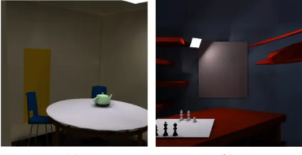
Figure 4: Test scenes (a)Teatime(b)Chesstime.
Neighboring Information Included in VS OUTPUT (VS OUTPUT): Instead of us-ing the adjacency structure as input data, we modify the VS OUTPUT structure for keeping the necessary neighboring information, avoiding the costly accesses to texture memory. The newVS OUTPUTsimply adds this field to the structure in Listing 1:
6 float4 n e i g h b o r s [12] : N E I G H B O R S ;
The prototype of the kernel is the same that in the NITM case, passing just the three vertices of the tri-angle to be processed. Adding all the neighboring data needed for the computation to the three input ver-tices may seem quite redundant, but although we are replicating part of the neighboring information, this is completely compensated by the increase in the per-formance achieved by avoiding the texture memory accesses. As a matter of fact, there is only needed to access texture memory in the infrequent case when the number of adjacent triangles is greater than 12.
4
EXPERIMENTAL RESULTS
In this section we discuss the performance of our GPU proposal for the rendering phase of the target multiresolution system. All the results have been obtained in a computer with processor Intel Core i7 920 2.67 GHz, 6 GB of RAM and a video card ATI Radeon 5870. The software platform was Microsoft Windows 7 Ultimate 64 bits as operative system and the Microsoft Visual C++ 2008 compiler with HLSL Shader Model 4.0 and DirectX 10.
In the following, we include the results obtained with two of the scenes employed in our tests:Teatime
Table 1: Comparison of the three proposed alternatives (fps for surface subdivision).
OBJECT NITM TA VS OUTPUT OBJECT NITM TA VS OUTPUT
Pawn 1840 1966 4063 Teapot1720 1873 3970
Bishop1879 1989 4063 Spoon 1701 1810 3907
Queen 1850 1975 3998 Cup 1772 1920 3970
King 1820 1960 3975
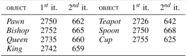
Table 2: Frames per second for rendering the multiresolu-tion objects in the test scenes.
OBJECT 1stit. 2ndit. OBJECT 1stit. 2ndit.
Pawn 2750 662 Teapot 2726 642
Bishop 2752 665 Spoon 2750 668
Queen 2735 660 Cup 2755 625
King 2742 659
In Table 1 we show the results (frames per sec-ond) obtained for the surface subdivision of the mul-tiresolution objects in the test scenes by the three im-plementations described in Section 3.3. As can be observed, all the results are more than enough for real time rendering. The worst results have been ob-tained by the NITM approach, due to the accesses to texture memory. There is an average improvement of 6.8% in the TA proposal as texture memory ac-cesses to vertices included in the adjacency structure are prevented. The table shows that the VS OUTPUT implementation gets an improvement of 120.8% and 106.6% regarding NITM and TA, respectively. This increase in the performance is produced by practically avoiding any access to texture memory. Since this op-tion is obviously the best approach, the rest of the re-sults shown in this sections refer exclusively to it.
Table 2 presents the rendering results (frames per second) for the whole rendering (surface subdivision + assignment of color) of the multiresolution objects for one and two levels of subdivision, whereas the re-sults for the whole scenes for two iterations are 530 and 260 fps, respectively forTeatimeandChesstime. FPS have been measured for the worst case, that is, when all the multiresolution objects are rendered. As can be observed, real time rendering has been achieved in all the cases, and the differences in ren-dering time between the two scenes are due to the number of primitives to process in both cases.
5
CONCLUSIONS
An efficient GPU implementation of the Loop sur-face subdivision scheme has been presented in this work. This implementation has been integrated in a multiresolution system, mapping the color results
tained from global illumination in the subdivided ob-jects. Among the different options analyzed for per-forming tessellation on a GPU, we have opted for using the geometry shader. Even so, our proposal is recomputation-based, so many redundant compu-tations are made because of the geometry shader con-straint that does not allow the synchronization among tasks. However, these redundant computations does not deteriorate the performance, as have been shown. Furthermore, an analysis of three different options for accessing the necessary neighboring information in the geometry shader has been done. As a result, directly passing data though vertex buffer has got the best results since most of the accesses to texture mem-ory are avoided. Our implementation achieves a great performance, rendering all the test scenes in real time.
REFERENCES
Garland, M., Willmot, A., and Heckbert, P. H. (2001). Hi-erarchical face clustering on polygonal surfaces. In
I3D ’01: Proceedings of the 2001 Symposium on In-teractive 3D Graphics, pages 49–58, Research Trian-gle Park, NC. ACM, New York, NY, USA.
Gobbetti, E., Span`o, L., and Agus, M. (2003). Hierarchical higher order face cluster radiosity for global illumi-nation walkthroughs of complex non-diffuse environ-ments. Computer Graphics Forum, 22(3):563–572. Hanrahan, P., Saltzman, D., and Aupperle, L. (1991). A
rapid hierarchical radiosity algorithm. SIGGRAPH Comput. Graph., 25(4):197–206.
Loop, C. (1987). Smooth subdivision surfaces based on triangles. Master’s thesis, University of Utah, Dept. of Mathematics.
Loop, C. and Schaefer, S. (2008). Approximating catmull-clark subdivision surfaces with bicubic patches.ACM Transactions on Graphics, 1.
Lorenz, H. and D¨ollner, J. (2008). Dynamic mesh refine-ment on GPU using geometry shaders. InProc. of 16th Int. Conf. in Central Europe on Computer Graphics, Visualization and Computer (WSCG’08).
Padr´on, E. J., Amor, M., B´oo, M., and Doallo, R. (2010). Hierarchical radiosity for multiresolution sys-tems based on normal tests. The Computer Journal, 53(6):741–752.
Patney, A., Ebeida, M. S., and Owens, J. D. (2009). Par-allel View-Dependent Tessellation of Catmull-Clark Subdivision Surfaces. InProc. of the Conference on
High Performance Graphics 2009 (HPG’09), pages
99–108.
Shiue, L.-J., Jones, I., and Peters, J. (2005). A Real-time GPU Subdivision Kernel. ACM Trans. Graph., 24(3):1010–1015.