EVALUACIÓN – PRUEBA DE HABILIDADES PRÁCTICAS CCNA
JOHN HENRY CAMELO GAMBOA
UNIVERSIDAD NACIONAL ABIERTA Y A DISTANCIA UNAD CIENCIAS BÁSICAS, TECNOLOGÍA E INGENIERÍA
BOGOTÁ
2019
EVALUACION – PRUEBA DE HABILIDADES PRACTICAS CCNA
Diplomado de profundización Cisco Diseño e implementación de soluciones integradas LAN / WAN – Grupo 203092_2
JOHN HENRY CAMELO GAMBOA
Director de curso Juan Carlos Vesga
UNIVERSIDAD NACIONAL ABIERTA Y A DISTANCIA UNAD CIENCIAS BÁSICAS, TECNOLOGÍA E INGENIERÍA
Bogotá Junio de 2019
NOTA DE ACEPTACION
---
---
---
_
PRESIDENTE DEL JURADO
_
JURADO
_
CONTENIDO
LISTA DE TABLAS… ... 10
LISTA DE GRÁFICAS… ... 11
LISTA ANEXOS… ... 12
GLOSARIO ... 13
INTRODUCCIÓN ...14
OBJETIVOS… ... 15
ESCENARIO1 ... 16
1.1 Configuración del enrutamiento ... 17
1.1.1 Enrutamiento CPE ISP… ... 17
1.2 Configuracion Rip V2 ... 17
1.2.1 CPE Medellín1 ... 17
1.1.2.2 CPE Medellin2 ... 18
1.1.2.3 CPE Medellin3 ...18
1.1.3 Enrutamiento CPEs Bogotá ... 19
1.1.3.1 CPE Bogota1 ... 18
1.1.3.2 CPE Bogota2 ... 19
1.1.3.3 CPE Bogota3 ... 20
1.2 Configuracion Rip V2 ... 20
1.2.1 CPE Medellín1 ... 20
1.2.2 CPE Medellín2 ... 21
1.2.3 CPE Medellín3 ... 21
1.2.4 CPE Bogotá1 ... 22
1.2.5 CPE Bogotá2 ... 22
1.2.6 CPE Bogotá3 ... 23
1.3 Los routers Bogota1 y Medellín deberán añadir a su configuración de enrutamiento una ruta por defecto hacia el ISP y, a su vez, redistribuirla dentro de las publicaciones de RIP ... 23
1.3.1 Ruta por defecto hacia ISP y RIP ... 23
1.3.1.1 Medellin1 ... 23
1.3.1.2 Bogotá1 ... 24
1.4 El router ISP deberá tener una ruta estática dirigida hacia cada red interna de Bogotá y Medellín para el caso se sumarizan las subredes de cada uno a /2..24
1.4.1 Configuracion ISP ... 24
1.4.2 Tabla de Enrutamiento. Verificar la tabla de enrutamiento en cada uno de los routers para comprobar las redes y sus rutas… ... 25
1.4.2.1 Tabla de enrutamiento ISP ... 25
1.4.2.5 CPE Bogota1 ... 29
1.4.2.6 CPE Bogota2 ... 30
1.4.2.7 CPE Bogota3 ... 31
1.5 Verificar el balanceo de carga que presentan los routers ... 32
1.5.1 Rutas redundantes ...32
1.5.1.1 CPE Bogota3 ... 32
1.5.2 Obsérvese en los routers Bogotá1 y Medellín1 cierta similitud por su ubicación, por tener dos enlaces de conexión hacia otro router y por la ruta por defecto que manejan... 33
1.5.2.1 CPE Medellin1 ...33
1.5.2.2 CPE Bogota1 ... 34
1.6 Los routers Medellín2 y Bogotá2 también presentan redes conectadas directamente y recibidas mediante RIP ... 35
1.6.1 CPE Medellin2 ... 35
1.6.2 CPE Bogota2 ... 36
1.7 Las tablas de los routers restantes deben permitir visualizar rutas redundantes para el caso de la ruta por defecto ... 37
1.8 El router ISP solo debe indicar sus rutas estáticas adicionales a las directamente conectadas. ... 38
1.8.1 CPE ISP ... 38
2. Parte 3: Deshabilitar la propagación del protocolo RIP ... 39
2.1 Para no propagar las publicaciones por interfaces que no lo requieran se debe deshabilitar la propagación del protocolo RIP, en la siguiente tabla se indican las interfaces de cada router que no necesitan desactivación ... 39
2.2 Parte 4: Verificación del protocolo RIP ... 39
2.2.1 Verificar y documentar las opciones de enrutamiento configuradas en los routers, como el passive interface para la conexión hacia el ISP, la versión de RIP y las interfaces que participan de la publicación entre otros datos..39
2.2.2 Verificar y documentar la base de datos de RIP de cada router, donde se informa de manera detallada de todas las rutas hacia cada red ... 39
2.2.2.1 CPE Medellin1 RIP… ... 40
2.2.2.2 CPE Medellin2 RIP ... 40
2.2.2.3 CPE Medellin3 RIP ... 41
2.2.2.4 CPE Bogota1 RIP ... 41
2.2.2.5 CPE Bogota2 RIP ... 42
2.2.2.6 CPE Bogota3 RIP ... 42
2.4 Parte 6: Configuración de PAT ... 44
2.4.1 En la topología, si se activa NAT en cada equipo de salida (Bogotá1 y Medellín1), los routers internos de una ciudad no podrán llegar hasta los routers internos en el otro extremo, sólo existirá comunicación hasta los routers Bogotá1, ISP y Medellín1 ... 44
2.4.1.1 CPE Medellin1 ...44
2.4.1.2 CPE Bogota1 ... 45
2.4.2 Después de verificar lo indicado en el paso anterior proceda a configurar el NAT en el router Medellín1. Compruebe que la traducción de direcciones indique las interfaces de entrada y de salida. Al realizar una prueba de ping, la dirección debe ser traducida automáticamente a la dirección de la interfaz serial 0/1/0 del router Medellín1, cómo diferente puerto ... 45
2.5 Proceda a configurar el NAT en el router Bogotá1. Compruebe que la traducción de direcciones indique las interfaces de entrada y de salida. Al realizar una prueba de ping, la dirección debe ser traducida automáticamente a la dirección de la interfaz serial 0/1/0 del router Bogotá1, cómo diferente puerto ... 46
2.5.1 CPE Bogota3 ... 46
2.6 Parte 7: Configuración del servicio DHCP ... 46
2.6.1 Configurar la red Medellín2 y Medellín3 donde el router Medellín 2 debe ser el servidor DHCP para ambas redes Lan ... 46
2.6.1.1 CPE Medellin2 ... 46
2.6.1.2 CPE Medellin3 ... 47
2.6.2 El router Medellín3 deberá habilitar el paso de los mensajes broadcast hacia la IP del router Medellín2 ... 47
2.6.3 Configurar la red Bogotá2 y Bogotá3 donde el router Medellín2 debe ser el servidor DHCP para ambas redes Lan ... 47
2.6.3.1 CPE Bogota2 ... 47
2.6.3.2 CPE Bogota3 ... 48
2.6.4 Configure el router Bogotá1 para que habilite el paso de los mensajes Broadcast hacia la IP del router Bogotá2 ... 48
ESCENARIO2 ... 49
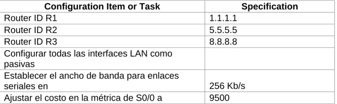
3. Configurar el direccionamiento IP acorde con la topología de red para cada uno de los dispositivos que forman parte del escenario ... 50
3.1 Configuración básica Router R1 ... 50
3.2 Configuración básica Router R2 ...50
3.3 Configuración básica Router R3 ...51
4.1 SW1 Config. interfaz F 0/3 Modo Troncal ... 52
5. Config. interfaz Modo Acceso ... 54
5.1 SW1 ... 54
5.2 Se dejan en estado Down las interfaces libres ... 54
5.3 Se Configura la VLAN de Mantenimiento e IP del Switch ... 56
6. SW 3 ... 56
6.1 Config. VLANs en SW 3 ... 56
6.2 Config. VLANs de Mantenimiento SW 3 ... 57
6.3 Configuración GW ... 57
6.4 Config. Troncal Interfaz F 0/3 ... 57
6.5 Config. Puertos modo Acceso ... 58
6.6 Config. Puerto f 0/1 y dejar en Down las interfaces libres ... 58
7. CONFIGURACION R1 BOGOTA ... 60
7.1 Config. Interfaz Bogota- Miami ... 60
7.2 Ruta de salida por interfaz S0/0/0 ... 60
8. CONFIGURACION R2 MIAMI ... 60
8.1 Config. Interfaz Miami- Bogota ... 60
8.2 Config. Interfaz Miami- Buenos Aires… ... 61
8.3 Config. Salida a Internet ... 61
8.4 Config. hacia webServer ... 62
9. CONFIGURACION R3 BUENOS AIRES ... 62
9.1 Configuración CPE Buenos Aires ... 62
9.2 Config. Conexión Buenos Aires-Miami ... 62
9.3 Config. Loopback 4 - R3 ... 62
9.4 Config. Loopback 5 - R3 ... 63
9.5 Config. Loopback 6 - R3 ... 63
10. Configuracion servidor web ... 64
10.1 Configuracion 802.1Q en R1 ... 64
10.2 Config. 802.1Q – R1 ... 65
10.3 Config. Int. F0/0 – R1 ... 65
11. Configurar el protocolo de enrutamiento OSPFv2 bajo los siguientes criterios ... 66
11.1 Configurar VLANs, Puertos troncales, puertos de acceso, encapsulamiento, Inter-VLAN Routing y Seguridad en los Switches acorde a la topología de red establecida ... 67
11.2 En el Switch 3 deshabilitar DNS lookup ... 67
11.3 Asignar direcciones IP a los Switches acorde a los lineamientos ... 67
configuraciones estáticas ... 67 11.8 Configurar NAT en R2 para permitir que los host puedan salir a internet….67 11.9 Configurar al menos dos listas de acceso de tipo estándar a su criterio en
para restringir o permitir tráfico desde R1 o R3 hacia R2 ... 67 Desarrollo punto 11 a 11.9
Pag.
LISTA DE GRÁFICAS
Pag.
Pág.
GLOSARIO
ENCAPSULAMIENTO: Proceso mediante el cual un mensaje se empaqueta en un formato llamado trama, el cual contiene la información de dirección origen y dirección destino, es lo mismo que la información que se debe diligenciar en una carta, si esta no la recibe el destinatario se devuelve a quien la remitió.
NAT: La traducción de direcciones de red (NAT) está diseñada para conservar direcciones IP. Permite que se conecten a Internet las redes de IP privada que emplean direcciones IP no registradas. NAT opera en routers, que en general conectan dos redes, y convierte las direcciones privadas (no exclusivas globalmente) de la red interna en direcciones legales, antes de que se reenvíen los paquetes a otra red.
PING: Packet Internet Groper. Este comando se utiliza para comprobar si una determinada interfaz de red, de nuestra computadora o de otra, se encuentra activa.
El ping envía paquetes al IP o host que se le indique, y nos dice cuanto tiempo demoró el paquete en ir y regresar, entre otras pocas informaciones.
Ping se usa para: resolver el nombre de host para saber su IP o simplemente verificar si una máquina está prendida.
Un "ping" sin respuesta no necesariamente significa que la computadora no existe o está apagada. Si el host o ip al cual se le hace ping tiene un firewall que no permite las respuestas al protocolo ICMP, entonces el "ping" no puede proporcionarnos información.
PROTOCOLO: son una serie de normas y reglas utilizadas por equipos por las cuales dos o más sistemas diferentes deben permitir la conexión, comunicación e intercambiar información.
INTRODUCCIÓN
Si queremos ser parte de este mundo tan cambiante debemos de prepararnos para enfrentarlo como profesionales, por esto la UNIVERSIDAD NACIONAL ABIERTA Y A DISTANCIA UNAD consciente de los cambios que se están produciendo y la globalización, tiene un convenio con Cisco una de las grandes empresas de soluciones de conectividad a nivel global, quién a puesto a
disposición de los estudiantes de la Universidad la opción de grado con el Diplomado de Diseño e Implementación de soluciones integradas LAN y WAN.
OBJETIVOS
GENERAL
Desarrollar habilidades que nos ayudarán en nuestra vida profesional en el área de redes como futuros Ingenieros de Sistemas egresados de la Universidad Nacional Abierta y a Distancia UNAD
ESPECIFICOS
• Desarrollar configuraciones básicas de red.
• Identificar problemas de red y poder solucionarlos de manera adecuada con
la utilización de herramientas y commandos propios de Cisco.
• Realizar configuraciones de VLAN, protocolos OSPF, redes dhcp.
• Desarrollar habilidades en configuraciones complejas de red.
ESCENARIO 1
Una empresa posee sucursales distribuidas en las ciudades de Bogotá y Medellín, en donde el estudiante será el administrador de la red, el cual deberá configurar e interconectar entre sí cada uno de los dispositivos que forman parte del escenario, acorde con los lineamientos establecidos para el direccionamiento IP, protocolos de enrutamiento y demás aspectos que forman parte de la topología de red.
Topología de red
Diagrama 1. Escenario 1
Este escenario plantea el uso de RIP como protocolo de enrutamiento, considerando que se tendran rutas por defecto redistribuidas; asimismo, habilitar el encapsulamiento PPP y su autenticación.
Los routers Bogota2 y medellin2 proporcionan el servicio DHCP a su propia red LAN y a los routers 3 de cada ciudad.
Debe configurar PPP en los enlaces hacia el ISP, con autenticación.
Debe habilitar NAT de sobrecarga en los routers Bogota1 y medellin1.
Desarrollo
Como trabajo inicial se debe realizar lo siguiente.
• Realizar las rutinas de diagnóstico y dejar los equipos listos para su configuración (asignar nombres de equipos, asignar claves de seguridad, etc).
Configurar la topología de red, de acuerdo con las siguientes especificaciones.
1.1 Configuración del enrutamiento
Configurar el enrutamiento en la red usando el protocolo RIP versión 2, declare la red principal, desactive la sumarización automática.
1.1.1 Enrutamiento CPE ISP
ISP#conf t
Enter configuration commands, one per line. End with CNTL/Z. ISP(config)#int s0/0/0
ISP(config-if)#ip address 209.17.220.1 255.255.255.252 ISP(config-if)#clock rate 4000000
This command applies only to DCE interfaces ISP(config-if)#no shut
ISP(config-if)#int s0/0/1
ISP(config-if)#ip address 209.17.220.5 255.255.255.252 ISP(config-if)#clock rate 4000000
ISP(config-if)#no shut ISP(config-if)#
1.1.2 Enrutamiento CPEs Medellin 1.1.2.1 CPE Medellin1
Medellin1#conf t
Enter configuration commands, one per line. End with CNTL/Z. Medellin1(config)#int s0/0/0
Medellin1(config-if)#ip address 209.17.220.2 255.255.255.252 Medellin1(config-if)#no shut
Medellin1(config-if)#
Medellin1(config-if)#int s0/0/1
Medellin1(config-if)#ip address 172.29.6.1 255.255.255.252 Medellin1(config-if)#clock rate 4000000
Medellin1(config-if)#no shut
Medellin1(config-if)#
Medellin1(config-if)#int s0/1/0
Medellin1(config-if)#ip address 172.29.6.9 255.255.255.252 Medellin1(config-if)#clock rate 4000000
Medellin1(config-if)#no shut Medellin1(config-if)#
Medellin1(config-if)#ip address 172.29.6.13 255.255.255.252 Medellin1(config-if)#clock rate 4000000
Medellin1(config-if)#no shut Medellin1(config-if)#
1.1.2.2 CPE Medellin2
Medellin2#conf t Medellin2(config)#
Medellin2(config)#int s0/0/0
Medellin2(config-if)#ip address 172.29.6.2 255.255.255.252 Medellin2(config-if)#no shut
Medellin2(config-if)#
Medellin2(config-if)#int s0/0/1
Medellin2(config-if)#ip address 172.29.6.5 255.255.255.252 Medellin2(config-if)#clock rate 4000000
This command applies only to DCE interfaces Medellin2(config-if)#no shut
Medellin2(config-if)#
Medellin2(config-if)#int g0/0
Medellin2(config-if)#ip address 172.29.4.1 255.255.255.128 Medellin2(config-if)#no shut
Medellin2(config-if)#
1.1.2.3 CPE Medellin3
Medellin3#conf t
Enter configuration commands, one per line. End with CNTL/Z. Medellin3(config)#int s0/0/1
Medellin3(config-if)#ip address 172.29.6.14 255.255.255.252 Medellin3(config-if)#no shut
Medellin3(config-if)#
Medellin3(config-if)#int s0/1/0
Medellin3(config-if)#ip address 172.29.6.6 255.255.255.252 Medellin3(config-if)#no shut
Medellin3(config-if)#
Medellin3(config-if)#int g0/0
Medellin3(config-if)#ip address 172.29.4.129 255.255.255.128 Medellin3(config-if)#no shut
1.1.3 Enrutamiento CPEs Bogotá 1.1.3.1 CPE Bogota1
Bogota1#conf t
Enter configuration commands, one per line. End with CNTL/Z. Bogota1(config)#
Bogota1(config)#
Bogota1(config)#int s0/0/0
Bogota1(config-if)#ip address 209.17.220.6 255.255.255.252 Bogota1(config-if)#no shut
Bogota1(config-if)#
Bogota1(config-if)#int s0/0/1
Bogota1(config-if)#ip address 172.29.3.9 255.255.255.252 Bogota1#conf t
Enter configuration commands, one per line. End with CNTL/Z. Bogota1(config)#
Bogota1(config)#int s0/0/0
Bogota1(config-if)#ip address 209.17.220.6 255.255.255.252 Bogota1(config-if)#no shut
Bogota1(config-if)#
Bogota1(config-if)#int s0/0/1
Bogota1(config-if)#ip address 172.29.3.9 255.255.255.252
1.1.3.2 CPE Bogota2
Bogota2(config)#
Bogota2(config)#int s0/0/0
Bogota2(config-if)#ip address 172.29.3.10 255.255.255.252 Bogota2(config-if)#no shut
Bogota2(config-if)#
Bogota2(config-if)#int s0/0/1
Bogota2(config-if)#ip address 172.29.3.13 255.255.255.252 Bogota2(config-if)#clock rate 4000000
Bogota2(config-if)#no shut Bogota2(config-if)#
Bogota2(config-if)#int g0/0
Bogota2(config-if)#ip address 172.29.1.1 255.255.255.0 Bogota2(config-if)#no shut
Bogota2(config-if)#
Bogota3(config)#
Bogota3(config)#int s0/0/0
Bogota3(config-if)#ip address 172.29.3.2 255.255.255.252 Bogota3(config-if)#no shut
Bogota3(config-if)#
Bogota3(config-if)#int s0/0/1
Bogota3(config-if)#ip address 172.29.3.6 255.255.255.252 Bogota3(config-if)#no shut
Bogota3(config-if)# Bogota3#conf t
Bogota3(config)#int s0/1/0
Bogota3(config-if)#ip address 172.29.3.14 255.255.255.252 Bogota3(config-if)#no shut
Bogota3(config-if)#
Bogota3(config-if)#int g0/0
Bogota3(config-if)#ip address 172.29.0.1 255.255.255.0 Bogota3(config-if)#no shut
Bogota3(config-if)#
---
1.2 Configuracion Rip V2 1.2.1 CPE Medellín1
Medellin1>en Medellin1#conf t
Enter configuration commands, one per line. End with CNTL/Z. Medellin1(config)#router rip
Medellin1(config-router)#version 2 Medellin1(config-router)#no auto-
Medellin1(config-router)#no auto-summary
Medellin1(config-router)#do sh ip route connected C 172.29.6.0/30 is directly connected, Serial0/0/1 C 172.29.6.8/30 is directly connected, Serial0/1/0 C 172.29.6.12/30 is directly connected, Serial0/1/1 C 209.17.220.0/30 is directly connected, Serial0/0/0
1.2.2 CPE Medellín2
Medellin2>EN Medellin2#conf t
Enter configuration commands, one per line. End with CNTL/Z. Medellin2(config)#router rip
Medellin2(config-router)#version 2 Medellin2(config-router)#no auto-s
Medellin2(config-router)#no auto-summary
Medellin2(config-router)#do show ip route connected C 172.29.4.0/25 is directly connected, GigabitEthernet0/0 C 172.29.6.0/30 is directly connected, Serial0/0/0
C 172.29.6.4/30 is directly connected, Serial0/0/1 Medellin2(config-router)#network 172.29.4.0 Medellin2(config-router)#network 172.29.6.0 Medellin2(config-router)#network 172.29.6.4 Medellin2(config-router)#
1.2.3 CPE Medellín3
Router>en Router#conf t
Enter configuration commands, one per line. End with CNTL/Z. Router(config)#router rip
Router(config-router)#version 2
Router(config-router)#no auto-summary
Router(config-router)#do show ip route connected
C 172.29.4.128/25 is directly connected, GigabitEthernet0/0 C 172.29.6.4/30 is directly connected, Serial0/1/0
C 172.29.6.8/30 is directly connected, Serial0/0/0 C 172.29.6.12/30 is directly connected, Serial0/0/1
Router(config-router)#exit
Router(config)#hostname Medellin3 Medellin3(config)#
1.2.4 CPE Bogotá1
Bogota1>en Bogota1#conf t
Enter configuration commands, one per line. End with CNTL/Z. Bogota1(config)#router rip
Bogota1(config-router)#version 2
Bogota1(config-router)#no auto-summary
Bogota1(config-router)#do show ip route connected C 172.29.3.0/30 is directly connected, Serial0/1/0 C 172.29.3.4/30 is directly connected, Serial0/1/1 C 172.29.3.8/30 is directly connected, Serial0/0/1 C 209.17.220.4/30 is directly connected, Serial0/0/0
Bogota1(config-router)#network 172.29.3.0 Bogota1(config-router)#network 172.29.3.4 Bogota1(config-router)#network 172.29.3.8 Bogota1(config-router)#
1.2.5 CPE Bogotá2
Bogota2(config)#router rip
Bogota2(config-router)#version 2
Bogota2(config-router)#no auto-summary
Bogota2(config-router)#do show ip route connected
C 172.29.1.0/24 is directly connected, GigabitEthernet0/0 C 172.29.3.8/30 is directly connected, Serial0/0/0
C 172.29.3.12/30 is directly connected, Serial0/0/1
1.2.6 CPE Bogotá3
Bogota3(config)#router rip
Bogota3(config-router)#version 2 Bogota3(config-router)#no auto-s
Bogota3(config-router)#no auto-summary
Bogota3(config-router)#do show ip route connected
C 172.29.0.0/24 is directly connected, GigabitEthernet0/0 C 172.29.3.0/30 is directly connected, Serial0/0/0
C 172.29.3.4/30 is directly connected, Serial0/0/1 C 172.29.3.12/30 is directly connected, Serial0/1/0
Bogota3(config-router)#network 172.29.3.0 Bogota3(config-router)#network 172.29.3.4 Bogota3(config-router)#network 172.29.3.12 Bogota3(config-router)#network 172.29.0.0 Bogota3(config-router)#
1.3 Los routers Bogota1 y Medellín deberán añadir a su configuración de enrutamiento una ruta por defecto hacia el ISP y, a su vez, redistribuirla dentro de las publicaciones de RIP.
13.1. Ruta por defecto hacia ISP y RIP 1.3.1.1 Medellin1
Medellin1#conf t
Enter configuration commands, one per line. End with CNTL/Z.
Medellin1(config)#ip route 0.0.0.0 0.0.0.0 209.17.220.1
Medellin1(config)#router rip
Medellin1(config-router)#default-information origi
Medellin1(config-router)#default-information originate
1.3.1.2 Bogotá1
Bogota1(config)#
Bogota1(config)#ip route 0.0.0.0 0.0.0.0 209.17.220.5
Bogota1(config)#router rip
Bogota1(config-router)#default-information originate
Bogota1(config-router)#
1.4 El router ISP deberá tener una ruta estática dirigida hacia cada red interna de Bogotá y Medellín para el caso se sumarizan las subredes de cada uno a /22.
TABLA 1. Sumarización de redes.
1.4.1 Configuracion ISP
ISP>en
ISP#conf t
Enter configuration commands, one per line. End with CNTL/Z.
ISP(config)#
ISP(config)#ip route 172.29.4.0 255.255.252.0 209.17.220.2
ISP(config)#
1.4.2 Tabla de Enrutamiento.
a. Verificar la tabla de enrutamiento en cada uno de los routers para comprobar las redes y sus rutas.
1.4.2.1 Tabla de enrutamiento ISP
ISP#sh ip route
Codes: L - local, C - connected, S - static, R - RIP, M - mobile, B - BGP
D - EIGRP, EX - EIGRP external, O - OSPF, IA - OSPF inter area
N1 - OSPF NSSA external type 1, N2 - OSPF NSSA external type 2
E1 - OSPF external type 1, E2 - OSPF external type 2, E - EGP
i - IS-IS, L1 - IS-IS level-1, L2 - IS-IS level-2, ia - IS-IS inter area
* - candidate default, U - per-user static route, o - ODR
P - periodic downloaded static route
Gateway of last resort is not set
172.29.0.0/22 is subnetted, 2 subnets
S 172.29.0.0/22 [1/0] via 209.17.220.6
S 172.29.4.0/22 [1/0] via 209.17.220.2
209.17.220.0/24 is variably subnetted, 4 subnets, 2 masks
C 209.17.220.0/30 is directly connected, Serial0/0/0
L 209.17.220.1/32 is directly connected, Serial0/0/0
C 209.17.220.4/30 is directly connected, Serial0/0/1
L 209.17.220.5/32 is directly connected, Serial0/0/1
1.4.2.2 CPE Medellin1
Medellin1>en
Medellin1#sh ip route
Codes: L - local, C - connected, S - static, R - RIP, M - mobile, B - BGP
D - EIGRP, EX - EIGRP external, O - OSPF, IA - OSPF inter area
N1 - OSPF NSSA external type 1, N2 - OSPF NSSA external type 2
E1 - OSPF external type 1, E2 - OSPF external type 2, E - EGP
i - IS-IS, L1 - IS-IS level-1, L2 - IS-IS level-2, ia - IS-IS inter area
* - candidate default, U - per-user static route, o - ODR
P - periodic downloaded static route
Gateway of last resort is 209.17.220.1 to network 0.0.0.0
172.29.0.0/16 is variably subnetted, 9 subnets, 3 masks
R 172.29.4.0/25 [120/1] via 172.29.6.2, 00:00:12, Serial0/1/1
R 172.29.4.128/25 [120/2] via 172.29.6.2, 00:00:12, Serial0/1/1
C 172.29.6.0/30 is directly connected, Serial0/1/1
L 172.29.6.1/32 is directly connected, Serial0/1/1
R 172.29.6.4/30 [120/1] via 172.29.6.2, 00:00:12, Serial0/1/1
C 172.29.6.8/30 is directly connected, Serial0/0/1
L 172.29.6.9/32 is directly connected, Serial0/0/1
C 172.29.6.12/30 is directly connected, Serial0/1/0
L 172.29.6.13/32 is directly connected, Serial0/1/0
209.17.220.0/24 is variably subnetted, 2 subnets, 2 masks
C 209.17.220.0/30 is directly connected, Serial0/0/0
L 209.17.220.2/32 is directly connected, Serial0/0/0
S* 0.0.0.0/0 [1/0] via 209.17.220.1
1.4.2.3 CPE Medellin2
Medellin2#
Medellin2#sh ip route
Codes: L - local, C - connected, S - static, R - RIP, M - mobile, B - BGP
D - EIGRP, EX - EIGRP external, O - OSPF, IA - OSPF inter area
N1 - OSPF NSSA external type 1, N2 - OSPF NSSA external type 2
E1 - OSPF external type 1, E2 - OSPF external type 2, E - EGP
i - IS-IS, L1 - IS-IS level-1, L2 - IS-IS level-2, ia - IS-IS inter area
* - candidate default, U - per-user static route, o - ODR
P - periodic downloaded static route
Gateway of last resort is 172.29.6.1 to network 0.0.0.0
172.29.0.0/16 is variably subnetted, 9 subnets, 3 masks
C 172.29.4.0/25 is directly connected, GigabitEthernet0/0
L 172.29.4.1/32 is directly connected, GigabitEthernet0/0
R 172.29.4.128/25 [120/1] via 172.29.6.6, 00:00:05, Serial0/0/1
C 172.29.6.0/30 is directly connected, Serial0/0/0
L 172.29.6.2/32 is directly connected, Serial0/0/0
C 172.29.6.4/30 is directly connected, Serial0/0/1
L 172.29.6.5/32 is directly connected, Serial0/0/1
R 172.29.6.8/30 [120/1] via 172.29.6.1, 00:00:09, Serial0/0/0
[120/1] via 172.29.6.6, 00:00:05, Serial0/0/1
R 172.29.6.12/30 [120/1] via 172.29.6.1, 00:00:09, Serial0/0/0
[120/1] via 172.29.6.6, 00:00:05, Serial0/0/1
209.17.220.0/30 is subnetted, 1 subnets
R 209.17.220.0/30 [120/1] via 172.29.6.1, 00:00:09, Serial0/0/0
R* 0.0.0.0/0 [120/1] via 172.29.6.1, 00:00:09, Serial0/0/0
1.4.2.4 CPE Medellin3
Medellin3>en
Medellin3#sh ip route
Codes: L - local, C - connected, S - static, R - RIP, M - mobile, B - BGP
D - EIGRP, EX - EIGRP external, O - OSPF, IA - OSPF inter area
N1 - OSPF NSSA external type 1, N2 - OSPF NSSA external type 2
E1 - OSPF external type 1, E2 - OSPF external type 2, E - EGP
i - IS-IS, L1 - IS-IS level-1, L2 - IS-IS level-2, ia - IS-IS inter area
* - candidate default, U - per-user static route, o - ODR
P - periodic downloaded static route
Gateway of last resort is 172.29.6.5 to network 0.0.0.0
172.29.0.0/16 is variably subnetted, 10 subnets, 3 masks
R 172.29.4.0/25 [120/1] via 172.29.6.5, 00:00:01, Serial0/1/0
C 172.29.4.128/25 is directly connected, GigabitEthernet0/0
L 172.29.4.129/32 is directly connected, GigabitEthernet0/0
R 172.29.6.0/30 [120/1] via 172.29.6.5, 00:00:01, Serial0/1/0
C 172.29.6.4/30 is directly connected, Serial0/1/0
L 172.29.6.6/32 is directly connected, Serial0/1/0
C 172.29.6.8/30 is directly connected, Serial0/0/0
L 172.29.6.10/32 is directly connected, Serial0/0/0
C 172.29.6.12/30 is directly connected, Serial0/0/1
L 172.29.6.14/32 is directly connected, Serial0/0/1
209.17.220.0/30 is subnetted, 1 subnets
R 209.17.220.0/30 [120/2] via 172.29.6.5, 00:00:01, Serial0/1/0
R* 0.0.0.0/0 [120/2] via 172.29.6.5, 00:00:01, Serial0/1/0
1.4.2.5 CPE Bogota1
Bogota1#sh ip route
Codes: L - local, C - connected, S - static, R - RIP, M - mobile, B - BGP
D - EIGRP, EX - EIGRP external, O - OSPF, IA - OSPF inter area
N1 - OSPF NSSA external type 1, N2 - OSPF NSSA external type 2
E1 - OSPF external type 1, E2 - OSPF external type 2, E - EGP
i - IS-IS, L1 - IS-IS level-1, L2 - IS-IS level-2, ia - IS-IS inter area
* - candidate default, U - per-user static route, o - ODR
P - periodic downloaded static route
Gateway of last resort is 209.17.220.5 to network 0.0.0.0
172.29.0.0/16 is variably subnetted, 9 subnets, 3 masks
R 172.29.0.0/24 [120/1] via 172.29.3.2, 00:00:03, Serial0/1/0
[120/1] via 172.29.3.6, 00:00:03, Serial0/1/1
R 172.29.1.0/24 [120/1] via 172.29.3.10, 00:00:09, Serial0/0/1
C 172.29.3.0/30 is directly connected, Serial0/1/0
L 172.29.3.1/32 is directly connected, Serial0/1/0
C 172.29.3.4/30 is directly connected, Serial0/1/1
L 172.29.3.5/32 is directly connected, Serial0/1/1
C 172.29.3.8/30 is directly connected, Serial0/0/1
L 172.29.3.9/32 is directly connected, Serial0/0/1
R 172.29.3.12/30 [120/1] via 172.29.3.10, 00:00:09, Serial0/0/1
[120/1] via 172.29.3.2, 00:00:03, Serial0/1/0
[120/1] via 172.29.3.6, 00:00:03, Serial0/1/1
209.17.220.0/24 is variably subnetted, 2 subnets, 2 masks
C 209.17.220.4/30 is directly connected, Serial0/0/0
L 209.17.220.6/32 is directly connected, Serial0/0/0
S* 0.0.0.0/0 [1/0] via 209.17.220.5
1.4.2.6 CPE Bogota2
Bogota2#sh ip route
Codes: L - local, C - connected, S - static, R - RIP, M - mobile, B - BGP
D - EIGRP, EX - EIGRP external, O - OSPF, IA - OSPF inter area
N1 - OSPF NSSA external type 1, N2 - OSPF NSSA external type 2
E1 - OSPF external type 1, E2 - OSPF external type 2, E - EGP
i - IS-IS, L1 - IS-IS level-1, L2 - IS-IS level-2, ia - IS-IS inter area
* - candidate default, U - per-user static route, o - ODR
P - periodic downloaded static route
Gateway of last resort is 172.29.3.9 to network 0.0.0.0
172.29.0.0/16 is variably subnetted, 9 subnets, 3 masks
R 172.29.0.0/24 [120/1] via 172.29.3.14, 00:00:11, Serial0/0/1
C 172.29.1.0/24 is directly connected, GigabitEthernet0/0
L 172.29.1.1/32 is directly connected, GigabitEthernet0/0
R 172.29.3.0/30 [120/1] via 172.29.3.9, 00:00:20, Serial0/0/0
[120/1] via 172.29.3.14, 00:00:11, Serial0/0/1
R 172.29.3.4/30 [120/1] via 172.29.3.9, 00:00:20, Serial0/0/0
[120/1] via 172.29.3.14, 00:00:11, Serial0/0/1
C 172.29.3.8/30 is directly connected, Serial0/0/0
L 172.29.3.10/32 is directly connected, Serial0/0/0
C 172.29.3.12/30 is directly connected, Serial0/0/1
L 172.29.3.13/32 is directly connected, Serial0/0/1
209.17.220.0/30 is subnetted, 1 subnets
R 209.17.220.4/30 [120/1] via 172.29.3.9, 00:00:20, Serial0/0/0
R* 0.0.0.0/0 [120/1] via 172.29.3.9, 00:00:20, Serial0/0/0
1.4.2.7 CPE Bogota3
Bogota3#
Bogota3#sh ip route
Codes: L - local, C - connected, S - static, R - RIP, M - mobile, B - BGP
D - EIGRP, EX - EIGRP external, O - OSPF, IA - OSPF inter area
N1 - OSPF NSSA external type 1, N2 - OSPF NSSA external type 2
E1 - OSPF external type 1, E2 - OSPF external type 2, E - EGP
i - IS-IS, L1 - IS-IS level-1, L2 - IS-IS level-2, ia - IS-IS inter area
* - candidate default, U - per-user static route, o - ODR
P - periodic downloaded static route
Gateway of last resort is 172.29.3.5 to network 0.0.0.0
172.29.0.0/16 is variably subnetted, 10 subnets, 3 masks
C 172.29.0.0/24 is directly connected, GigabitEthernet0/0
L 172.29.0.1/32 is directly connected, GigabitEthernet0/0
R 172.29.1.0/24 [120/1] via 172.29.3.13, 00:00:04, Serial0/1/0
C 172.29.3.0/30 is directly connected, Serial0/0/0
L 172.29.3.2/32 is directly connected, Serial0/0/0
C 172.29.3.4/30 is directly connected, Serial0/0/1
L 172.29.3.6/32 is directly connected, Serial0/0/1
R 172.29.3.8/30 [120/1] via 172.29.3.1, 00:00:10, Serial0/0/0
[120/1] via 172.29.3.13, 00:00:04, Serial0/1/0
[120/1] via 172.29.3.5, 00:00:10, Serial0/0/1
C 172.29.3.12/30 is directly connected, Serial0/1/0
L 172.29.3.14/32 is directly connected, Serial0/1/0
209.17.220.0/30 is subnetted, 1 subnets
R 209.17.220.4/30 [120/1] via 172.29.3.1, 00:00:10, Serial0/0/0
[120/1] via 172.29.3.5, 00:00:10, Serial0/0/1
[120/1] via 172.29.3.1, 00:00:14, Serial0/0/0
[120/1] via 172.29.3.5, 00:00:14, Serial0/0/1 [120/1] via 172.29.3.1, 00:00:10, Serial0/0/0
Bogota3#
1.5 Verificar el balanceo de carga que presentan los routers.
1.5.1 Rutas redundantes 1.5.1.1 CPE Bogota3
Bogota3#sh ip route
Codes: L - local, C - connected, S - static, R - RIP, M - mobile, B - BGP
D - EIGRP, EX - EIGRP external, O - OSPF, IA - OSPF inter area
N1 - OSPF NSSA external type 1, N2 - OSPF NSSA external type 2
E1 - OSPF external type 1, E2 - OSPF external type 2, E - EGP
i - IS-IS, L1 - IS-IS level-1, L2 - IS-IS level-2, ia - IS-IS inter area
* - candidate default, U - per-user static route, o - ODR
P - periodic downloaded static route
Gateway of last resort is 172.29.3.1 to network 0.0.0.0
172.29.0.0/16 is variably subnetted, 10 subnets, 3 masks
C 172.29.0.0/24 is directly connected, GigabitEthernet0/0
L 172.29.0.1/32 is directly connected, GigabitEthernet0/0
R 172.29.1.0/24 [120/1] via 172.29.3.13, 00:00:01, Serial0/1/0
C 172.29.3.0/30 is directly connected, Serial0/0/0
L 172.29.3.2/32 is directly connected, Serial0/0/0
C 172.29.3.4/30 is directly connected, Serial0/0/1
L 172.29.3.6/32 is directly connected, Serial0/0/1
C 172.29.3.12/30 is directly connected, Serial0/1/0
L 172.29.3.14/32 is directly connected, Serial0/1/0
R* 0.0.0.0/0 [120/1] via 172.29.3.1, 00:00:14, Serial0/0/0
[120/1] via 172.29.3.5, 00:00:14, Serial0/0/1
Bogota3#
1.5.2 Obsérvese en los routers Bogotá1 y Medellín1 cierta similitud por su ubicación, por tener dos enlaces de conexión hacia otro router y por la ruta por defecto que manejan.
1.5.2.1 CPE Medellin1
Medellin1#sh ip route
Codes: L - local, C - connected, S - static, R - RIP, M - mobile, B - BGP
D - EIGRP, EX - EIGRP external, O - OSPF, IA - OSPF inter area
N1 - OSPF NSSA external type 1, N2 - OSPF NSSA external type 2
E1 - OSPF external type 1, E2 - OSPF external type 2, E - EGP
i - IS-IS, L1 - IS-IS level-1, L2 - IS-IS level-2, ia - IS-IS inter area
* - candidate default, U - per-user static route, o - ODR
P - periodic downloaded static route
Gateway of last resort is 209.17.220.1 to network 0.0.0.0
172.29.0.0/16 is variably subnetted, 9 subnets, 3 masks
R 172.29.4.0/25 [120/1] via 172.29.6.2, 00:00:12, Serial0/1/1
R 172.29.4.128/25 [120/2] via 172.29.6.2, 00:00:12, Serial0/1/1
C 172.29.6.0/30 is directly connected, Serial0/1/1
L 172.29.6.1/32 is directly connected, Serial0/1/1
R 172.29.6.4/30 [120/1] via 172.29.6.2, 00:00:12, Serial0/1/1
C 172.29.6.8/30 is directly connected, Serial0/0/1
L 172.29.6.9/32 is directly connected, Serial0/0/1
C 172.29.6.12/30 is directly connected, Serial0/1/0
209.17.220.0/24 is variably subnetted, 2 subnets, 2 masks
C 209.17.220.0/30 is directly connected, Serial0/0/0
L 209.17.220.2/32 is directly connected, Serial0/0/0
S* 0.0.0.0/0 [1/0] via 209.17.220.1
Medellin1#
1.5.2.2 CPE Bogota1
Bogota1#sh ip route
Codes: L - local, C - connected, S - static, R - RIP, M - mobile, B - BGP
D - EIGRP, EX - EIGRP external, O - OSPF, IA - OSPF inter area
N1 - OSPF NSSA external type 1, N2 - OSPF NSSA external type 2
E1 - OSPF external type 1, E2 - OSPF external type 2, E - EGP
i - IS-IS, L1 - IS-IS level-1, L2 - IS-IS level-2, ia - IS-IS inter area
* - candidate default, U - per-user static route, o - ODR
P - periodic downloaded static route
Gateway of last resort is 209.17.220.5 to network 0.0.0.0
172.29.0.0/16 is variably subnetted, 9 subnets, 3 masks
R 172.29.0.0/24 [120/1] via 172.29.3.2, 00:00:03, Serial0/1/0
[120/1] via 172.29.3.6, 00:00:03, Serial0/1/1
R 172.29.1.0/24 [120/1] via 172.29.3.10, 00:00:09, Serial0/0/1
C 172.29.3.0/30 is directly connected, Serial0/1/0
L 172.29.3.1/32 is directly connected, Serial0/1/0
C 172.29.3.4/30 is directly connected, Serial0/1/1
L 172.29.3.5/32 is directly connected, Serial0/1/1
C 172.29.3.8/30 is directly connected, Serial0/0/1
L 172.29.3.9/32 is directly connected, Serial0/0/1
R 172.29.3.12/30 [120/1] via 172.29.3.10, 00:00:09, Serial0/0/1
C 172.29.4.0/25 is directly connected, GigabitEthernet0/0
C 172.29.6.0/30 is directly connected, Serial0/0/0
C 172.29.6.4/30 is directly connected, Serial0/0/1
[120/1] via 172.29.3.6, 00:00:03, Serial0/1/1
209.17.220.0/24 is variably subnetted, 2 subnets, 2 masks
C 209.17.220.4/30 is directly connected, Serial0/0/0
L 209.17.220.6/32 is directly connected, Serial0/0/0
S* 0.0.0.0/0 [1/0] via 209.17.220.5
Bogota1#
1.6 Los routers Medellín2 y Bogotá2 también presentan redes conectadas directamente y recibidas mediante RIP.
1.6.1 CPE Medellin2
Medellin2#sh ip route
Codes: L - local, C - connected, S - static, R - RIP, M - mobile, B - BGP
D - EIGRP, EX - EIGRP external, O - OSPF, IA - OSPF inter area
N1 - OSPF NSSA external type 1, N2 - OSPF NSSA external type 2
E1 - OSPF external type 1, E2 - OSPF external type 2, E - EGP
i - IS-IS, L1 - IS-IS level-1, L2 - IS-IS level-2, ia - IS-IS inter area
* - candidate default, U - per-user static route, o - ODR
P - periodic downloaded static route
Gateway of last resort is 172.29.6.1 to network 0.0.0.0
172.29.0.0/16 is variably subnetted, 9 subnets, 3 masks
L 172.29.4.1/32 is directly connected, GigabitEthernet0/0
R 172.29.4.128/25 [120/1] via 172.29.6.6, 00:00:05, Serial0/0/1
L 172.29.6.2/32 is directly connected, Serial0/0/0
L 172.29.6.5/32 is directly connected, Serial0/0/1
[120/1] via 172.29.6.6, 00:00:05, Serial0/0/1
R 172.29.6.12/30 [120/1] via 172.29.6.1, 00:00:09, Serial0/0/0
[120/1] via 172.29.6.6, 00:00:05, Serial0/0/1
209.17.220.0/30 is subnetted, 1 subnets
R 209.17.220.0/30 [120/1] via 172.29.6.1, 00:00:09, Serial0/0/0
R* 0.0.0.0/0 [120/1] via 172.29.6.1, 00:00:09, Serial0/0/0
Medellin2#
1.6.2 CPE Bogota2
Bogota2#
Bogota2#sh ip route
Codes: L - local, C - connected, S - static, R - RIP, M - mobile, B - BGP
D - EIGRP, EX - EIGRP external, O - OSPF, IA - OSPF inter area
N1 - OSPF NSSA external type 1, N2 - OSPF NSSA external type 2
E1 - OSPF external type 1, E2 - OSPF external type 2, E - EGP
i - IS-IS, L1 - IS-IS level-1, L2 - IS-IS level-2, ia - IS-IS inter area
* - candidate default, U - per-user static route, o - ODR
P - periodic downloaded static route
Gateway of last resort is 172.29.3.9 to network 0.0.0.0
172.29.0.0/16 is variably subnetted, 9 subnets, 3 masks
R 172.29.0.0/24 [120/1] via 172.29.3.14, 00:00:11, Serial0/0/1
C 172.29.1.0/24 is directly connected, GigabitEthernet0/0
L 172.29.1.1/32 is directly connected, GigabitEthernet0/0
R 172.29.3.0/30 [120/1] via 172.29.3.9, 00:00:20, Serial0/0/0
[120/1] via 172.29.3.14, 00:00:11, Serial0/0/1
R 172.29.3.4/30 [120/1] via 172.29.3.9, 00:00:20, Serial0/0/0
[120/1] via 172.29.3.14, 00:00:11, Serial0/0/1
[120/1] via 172.29.3.5, 00:00:14, Serial0/0/1
L 172.29.3.10/32 is directly connected, Serial0/0/0
C 172.29.3.12/30 is directly connected, Serial0/0/1
L 172.29.3.13/32 is directly connected, Serial0/0/1
209.17.220.0/30 is subnetted, 1 subnets
R 209.17.220.4/30 [120/1] via 172.29.3.9, 00:00:20, Serial0/0/0
R* 0.0.0.0/0 [120/1] via 172.29.3.9, 00:00:20, Serial0/0/0
Bogota2#
1.7 Las tablas de los routers restantes deben permitir visualizar rutas redundantes para el caso de la ruta por defecto.
Gateway of last resort is 172.29.3.1 to network 0.0.0.0
172.29.0.0/16 is variably subnetted, 10 subnets, 3 masks
C 172.29.0.0/24 is directly connected, GigabitEthernet0/0
L 172.29.0.1/32 is directly connected, GigabitEthernet0/0
R 172.29.1.0/24 [120/1] via 172.29.3.13, 00:00:01, Serial0/1/0
C 172.29.3.0/30 is directly connected, Serial0/0/0
L 172.29.3.2/32 is directly connected, Serial0/0/0
C 172.29.3.4/30 is directly connected, Serial0/0/1
L 172.29.3.6/32 is directly connected, Serial0/0/1
R 172.29.3.8/30 [120/1] via 172.29.3.13, 00:00:01, Serial0/1/0 Rutas
Redundantes
Redundantes
Redundantes
C 172.29.3.12/30 is directly connected, Serial0/1/0
L 172.29.3.14/32 is directly connected, Serial0/1/0
R* 0.0.0.0/0 [120/1] via 172.29.3.1, 00:00:14, Serial0/0/0 Rutas Redundantes
Rutas Redundantes
[120/1] via 172.29.3.1, 00:00:14, Serial0/0/0 Rutas
C 209.17.220.0/30 is directly connected, Serial0/0/0
C 209.17.220.4/30 is directly connected, Serial0/0/1
1.8 El router ISP solo debe indicar sus rutas estáticas adicionales a las directamente conectadas.
1.8.1 CPE ISP
ISP#sh ip route
Codes: L - local, C - connected, S - static, R - RIP, M - mobile, B - BGP
D - EIGRP, EX - EIGRP external, O - OSPF, IA - OSPF inter area
N1 - OSPF NSSA external type 1, N2 - OSPF NSSA external type 2
E1 - OSPF external type 1, E2 - OSPF external type 2, E - EGP
i - IS-IS, L1 - IS-IS level-1, L2 - IS-IS level-2, ia - IS-IS inter area
* - candidate default, U - per-user static route, o - ODR
P - periodic downloaded static route
Gateway of last resort is not set
172.29.0.0/22 is subnetted, 2 subnets
S 172.29.0.0/22 [1/0] via 209.17.220.6
S 172.29.4.0/22 [1/0] via 209.17.220.2
209.17.220.0/24 is variably subnetted, 4 subnets, 2 masks
L 209.17.220.1/32 is directly connected, Serial0/0/0
L 209.17.220.5/32 is directly connected, Serial0/0/1
2. Parte 3: Deshabilitar la propagación del protocolo RIP.
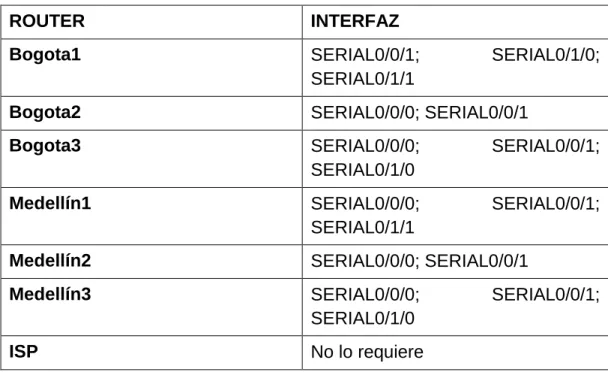
2.1 Para no propagar las publicaciones por interfaces que no lo requieran se debe deshabilitar la propagación del protocolo RIP, en la siguiente tabla se indican las interfaces de cada router que no necesitan desactivación.
ROUTER INTERFAZ
Bogota1 SERIAL0/0/1; SERIAL0/1/0;
SERIAL0/1/1
Bogota2 SERIAL0/0/0; SERIAL0/0/1
Bogota3 SERIAL0/0/0; SERIAL0/0/1;
SERIAL0/1/0
Medellín1 SERIAL0/0/0; SERIAL0/0/1;
SERIAL0/1/1
Medellín2 SERIAL0/0/0; SERIAL0/0/1
Medellín3 SERIAL0/0/0; SERIAL0/0/1;
SERIAL0/1/0
ISP No lo requiere
Tabla 2. Interfaces a deshabilitar. 2.2 Parte 4: Verificación del protocolo RIP.
2.2.1 Verificar y documentar las opciones de enrutamiento configuradas en los routers, como el passive interface para la conexión hacia el ISP, la versión de RIP y las interfaces que participan de la publicación entre otros datos.
2.2.2 Verificar y documentar la base de datos de RIP de cada router, donde se informa de manera detallada de todas las rutas hacia cada red.
Medellin1>en Medellin1#conf t
Enter configuration commands, one per line. End with CNTL/Z. Medellin1(config)#router rip
Medellin1(config-router)#version 2 Medellin1(config-router)#no auto-
Medellin1(config-router)#no auto-summary
Medellin1(config-router)#do sh ip route connected C 172.29.6.0/30 is directly connected, Serial0/0/1 C 172.29.6.8/30 is directly connected, Serial0/1/0 C 172.29.6.12/30 is directly connected, Serial0/1/1 C 209.17.220.0/30 is directly connected, Serial0/0/0
Medellin1(config-router)#network 172.29.6.0 Medellin1(config-router)#network 172.29.6.8 Medellin1(config-router)#network 172.29.6.12 Medellin1(config-router)#passive-interface s0/1/1
2.2.2.2 CPE Medellin2 RIP
Medellin2>EN Medellin2#conf t
Enter configuration commands, one per line. End with CNTL/Z. Medellin2(config)#router rip
Medellin2(config-router)#version 2 Medellin2(config-router)#no auto-s
Medellin2(config-router)#no auto-summary
Medellin2(config-router)#do show ip route connected C 172.29.4.0/25 is directly connected, GigabitEthernet0/0 C 172.29.6.0/30 is directly connected, Serial0/0/0
C 172.29.6.4/30 is directly connected, Serial0/0/1
Medellin2(config-router)#network 172.29.4.0 Medellin2(config-router)#network 172.29.6.0 Medellin2(config-router)#network 172.29.6.4 Medellin2(config-router)# passive-interface g0/0
Router>en Router#conf t
Enter configuration commands, one per line. End with CNTL/Z. Router(config)#router rip
Router(config-router)#version 2
Router(config-router)#no auto-summary
Router(config-router)#do show ip route connected
C 172.29.4.128/25 is directly connected, GigabitEthernet0/0 C 172.29.6.4/30 is directly connected, Serial0/1/0
C 172.29.6.8/30 is directly connected, Serial0/0/0 C 172.29.6.12/30 is directly connected, Serial0/0/1
Router(config-router)#network 172.29.4.128 Router(config-router)#network 172.29.6.4 Router(config-router)#network 172.29.6.8 Router(config-router)#network 172.29.6.12 Router(config-router)# passive-interface g0/0 Router(config-router)#exit
Router(config)#hostname Medellin3 Medellin3(config)#
2.2.2.4 CPE Bogota1 RIP
Bogota1>en Bogota1#conf t
Enter configuration commands, one per line. End with CNTL/Z. Bogota1(config)#router rip
Bogota1(config-router)#version 2
Bogota1(config-router)#no auto-summary
Bogota1(config-router)#do show ip route connected C 172.29.3.0/30 is directly connected, Serial0/1/0 C 172.29.3.4/30 is directly connected, Serial0/1/1 C 172.29.3.8/30 is directly connected, Serial0/0/1 C 209.17.220.4/30 is directly connected, Serial0/0/0
Bogota1(config-router)#network 172.29.3.0 Bogota1(config-router)#network 172.29.3.4 Bogota1(config-router)#network 172.29.3.8 Bogota1(config-router)# passive-interface s0/0/1
Bogota2(config)#router rip
Bogota2(config-router)#version 2
Bogota2(config-router)#no auto-summary
Bogota2(config-router)#do show ip route connected
C 172.29.1.0/24 is directly connected, GigabitEthernet0/0 C 172.29.3.8/30 is directly connected, Serial0/0/0
C 172.29.3.12/30 is directly connected, Serial0/0/1
Bogota2(config-router)#network 172.29.3.8 Bogota2(config-router)#network 172.29.3.12 Bogota2(config-router)# passive-interface g0/0
2.2.2.6 CPE Bogota3 RIP
Bogota3(config)#router rip
Bogota3(config-router)#version 2 Bogota3(config-router)#no auto-s
Bogota3(config-router)#no auto-summary
Bogota3(config-router)#do show ip route connected
C 172.29.0.0/24 is directly connected, GigabitEthernet0/0 C 172.29.3.0/30 is directly connected, Serial0/0/0
C 172.29.3.4/30 is directly connected, Serial0/0/1 C 172.29.3.12/30 is directly connected, Serial0/1/0
Bogota3(config-router)#network 172.29.3.0 Bogota3(config-router)#network 172.29.3.4 Bogota3(config-router)#network 172.29.3.12 Bogota3(config-router)#network 172.29.0.0 Bogota3(config-router)# passive-interface g0/0
2.3 Parte 5: Configurar encapsulamiento y autenticación PPP.
2.3.1 Según la topología se requiere que el enlace Medellín1 con ISP sea configurado con autenticación PAT.
ISP#conf t
Enter configuration commands, one per line. End with CNTL/Z. ISP(config)#username Medellin1
ISP(config)#username Medellin1 password cisco ISP(config)#
ISP(config-if)#encapsulation ppp ISP(config-if)#
%LINEPROTO-5-UPDOWN: Line protocol on Interface Serial0/0/0, changed state to down
ISP(config-if)#ppp auth
ISP(config-if)#ppp authentication pap
ISP(config-if)#ppp pap sent-username ISP password cisco ISP(config-if)#
ISP#ping 209.17.220.2
Type escape sequence to abort.
Sending 5, 100-byte ICMP Echos to 209.17.220.2, timeout is 2 seconds: !!!!!
Success rate is 100 percent (5/5), round-trip min/avg/max = 1/2/6 ms
ISP#ping 209.17.220.1
Type escape sequence to abort.
Sending 5, 100-byte ICMP Echos to 209.17.220.1, timeout is 2 seconds: !!!!!
Success rate is 100 percent (5/5), round-trip min/avg/max = 2/4/10 ms
ISP#
2.3.2 El enlace Bogotá1 con ISP se debe configurar con autenticación CHAT.
ISP#conf t
Enter configuration commands, one per line. End with CNTL/Z. ISP(config)#int s0/0/1
ISP(config-if)#encapsulation ppp ISP(config-if)#
%LINEPROTO-5-UPDOWN: Line protocol on Interface Serial0/0/1, changed state to down
ISP(config-if)#ppp chap sent-username ISP password cisco ^
% Invalid input detected at '^' marker.
ISP(config-if)#ppp pap sent-username ISP password cisco ISP(config-if)#exit
Bogota1(config)#int s0/0/0
Bogota1(config-if)#username ISP password cisco Bogota1(config)#int s0/0/0
Bogota1(config-if)#encap
Bogota1(config-if)#encapsulation ppp Bogota1(config-if)#
Bogota1(config-if)#ppp auth
Bogota1(config-if)#ppp authentication chap Bogota1(config-if)#
Bogota1(config-if)# Bogota1(config-if)#exit Bogota1(config)#exit Bogota1#
2.4 Parte 6: Configuración de PAT.
2.4.1 En la topología, si se activa NAT en cada equipo de salida (Bogotá1 y Medellín1), los routers internos de una ciudad no podrán llegar hasta los routers internos en el otro extremo, sólo existirá comunicación hasta los routers Bogotá1, ISP y Medellín1.
2.4.1.1 CPE Medellin1
Medellin1#ping 172.29.6.2 Type escape sequence to abort.
Sending 5, 100-byte ICMP Echos to 172.29.6.2, timeout is 2 seconds: !!!!!
Success rate is 100 percent (5/5), round-trip min/avg/max = 1/2/7 ms Medellin1#ping 172.29.6.14
Type escape sequence to abort.
Sending 5, 100-byte ICMP Echos to 172.29.6.14, timeout is 2 seconds: !!!!!
Success rate is 100 percent (5/5), round-trip min/avg/max = 1/3/10 ms
2.4.1.2 CPE Bogota1
Bogota1#ping 172.29.3.2
Type escape sequence to abort.
Sending 5, 100-byte ICMP Echos to 172.29.3.2, timeout is 2 seconds: !!!!!
Success rate is 100 percent (5/5), round-trip min/avg/max = 1/2/7 ms Bogota1#ping 172.29.3.10
Type escape sequence to abort.
Sending 5, 100-byte ICMP Echos to 172.29.3.10, timeout is 2 seconds: !!!!!
Success rate is 100 percent (5/5), round-trip min/avg/max = 1/2/7 ms
Bogota1#
2.4.2 Después de verificar lo indicado en el paso anterior proceda a configurar el NAT en el router Medellín1. Compruebe que la traducción de direcciones indique las interfaces de entrada y de salida. Al realizar una prueba de ping, la dirección debe ser traducida automáticamente a la dirección de la interfaz serial 0/1/0 del router Medellín1, cómo diferente puerto.
2.5 Proceda a configurar el NAT en el router Bogotá1. Compruebe que la traducción de direcciones indique las interfaces de entrada y de salida. Al realizar una prueba de ping, la dirección debe ser traducida automáticamente a la dirección de la interfaz serial 0/1/0 del router Bogotá1, cómo diferente puerto.
2.5.1 CPE Bogota3
Bogota3#
Bogota3#ping 172.29.3.5
Type escape sequence to abort.
Sending 5, 100-byte ICMP Echos to 172.29.3.5, timeout is 2 seconds: !!!!!
Success rate is 100 percent (5/5), round-trip min/avg/max = 1/2/7 ms
Bogota3#ping 172.29.3.6
Type escape sequence to abort.
Sending 5, 100-byte ICMP Echos to 172.29.3.6, timeout is 2 seconds: !!!!!
Success rate is 100 percent (5/5), round-trip min/avg/max = 2/4/11 ms
Bogota3#
2.6 Parte 7: Configuración del servicio DHCP.
2.6.1 Configurar la red Medellín2 y Medellín3 donde el router Medellín 2 debe ser el servidor DHCP para ambas redes Lan.
2.6.1.1 CPE Medellin2
Medellin2>en Medellin2#conf t
Enter configuration commands, one per line. End with CNTL/Z. Medellin2(config)#ip dhcp excluded-address 172.29.4.1 172.29.4.5 Medellin2(config)#
Medellin2(config)#ip dhcp excluded-address 172.29.4.129 172.29.4.133 Medellin2(config)#
Medellin2(config)#
Medellin2(config)#ip dhcp pool Medellin2
Medellin2(dhcp-config)#default-router 172.29.4.1 Medellin2(dhcp-config)#default-router 172.29.4.1 Medellin2(dhcp-config)#dns-server 8.8.8.8 Medellin2(dhcp-config)#
Medellin2(dhcp-config)#exit
Medellin2(config)#ip dhcp pool Medellin3
Medellin2(dhcp-config)#network 172.29.4.128 255.255.255.128 Medellin2(dhcp-config)#default-router 172.29.4.129
Medellin2(dhcp-config)#dns-server 8.8.8.8 Medellin2(dhcp-config)#exit
Medellin2(config)#
2.6.1.2 CPE Medellin3
Medellin3>en Medellin3#conf t
Enter configuration commands, one per line. End with CNTL/Z. Medellin3(config)#int g0/0
Medellin3(config-if)#ip helper-address 172.29.6.5 Medellin3(config-if)#
2.6.2 El router Medellín3 deberá habilitar el paso de los mensajes broadcast hacia la IP del router Medellín2.
2.6.3. Configurar la red Bogotá2 y Bogotá3 donde el router Medellín2 debe ser el servidor DHCP para ambas redes Lan.
2.6.3.1 CPE Bogota2
Bogota2>en Bogota2#conf t
Enter configuration commands, one per line. End with CNTL/Z. Bogota2(config)# ip dhcp excluded-address 172.29.1.1 172.29.1.5 Bogota2(config)# ip dhcp excluded-address 172.29.0.1 172.29.0.5 Bogota2(config)#ip dhcp pool Bogota2
Bogota2(dhcp-config)#network 172.29.1.0 255.255.255.0 Bogota2(dhcp-config)#default-router 172.29.1.1
Bogota2(dhcp-config)#dns-server 8.8.8.8 Bogota2(dhcp-config)#
Bogota2(dhcp-config)#ip dhcp pool Bogota3
Bogota2(dhcp-config)#default-router 172.29.0.1 Bogota2(dhcp-config)#dns-server 8.8.8.8
Bogota2(dhcp-config)#
2.6.3.2 CPE Bogota3
Bogota3>en Bogota3#conf t
Enter configuration commands, one per line. End with CNTL/Z. Bogota3(config)#int g0/0
Bogota3(config-if)#ip helper-address 172.29.3.13 Bogota3(config-if)#
2.6.4. Configure el router Bogotá1 para que habilite el paso de los mensajes Broadcast hacia la IP del router Bogotá2.
ESCENARIO 2
Escenario: Una empresa de Tecnología posee tres sucursales distribuidas en las ciudades de Miami, Bogotá y Buenos Aires, en donde el estudiante será el administrador de la red, el cual deberá configurar e interconectar entre sí cada uno de los dispositivos que forman parte del escenario, acorde con los lineamientos establecidos para el direccionamiento IP, protocolos de enrutamiento y demás aspectos que forman parte de la topología de red.
Diagrama 2. Escenario 2
3. Configurar el direccionamiento IP acorde con la topología de red para cada uno de los dispositivos que forman parte del escenario
3.1 Configuración básica Router R1
Router>EN Router#CONF T
Enter configuration commands, one per line. End with CNTL/Z. Router(config)#hostname Bogota
Bogota(config)#
Bogota(config)#no ip domain-lookup Bogota(config)#enable secret class Bogota(config)#line con 0
Bogota(config-line)#password cisco Bogota(config-line)#login
Bogota(config-line)#line vty 0 4 Bogota(config-line)#password cisco Bogota(config-line)#login
Bogota(config-line)#exit Bogota(config)#service pass
Bogota(config)#service password-encryption Bogota(config)#
Bogota(config)#banner mot
Bogota(config)#banner motd ##PROHIBIDO EL INGRESO A PERSONAL NO AUTORIZADO##
3.2 Configuración básica Router R2
Miami#conf t
Enter configuration commands, one per line. End with CNTL/Z. Miami(config)#no ip domain-lookup
Miami(config)#enable secret class Miami(config)#line con 0
Miami(config-line)#password cisco Miami(config-line)#login
Miami(config-line)#line vty 0 4 Miami(config-line)#password cisco Miami(config-line)#login
Miami(config-line)#exit Miami(config)#service pass
Miami(config)#banner motd ##PROHIBIDO EL INGRESO A PERSONAL NO AUTORIZADO##
Miami(config
3.3 Configuración básica Router R3
Router#conf t
Enter configuration commands, one per line. End with CNTL/Z. Router(config)#hostname Buenos_Aires
Buenos_Aires(config)#no ip domain-lookup Buenos_Aires(config)#enable secret class Buenos_Aires(config)#line con 0
Buenos_Aires(config-line)#password cisco Buenos_Aires(config-line)#login
Buenos_Aires(config-line)#line vty 0 4 Buenos_Aires(config-line)#password cisco Buenos_Aires(config-line)#login
Buenos_Aires(config-line)#exit Buenos_Aires(config)#service pass
Buenos_Aires(config)#service password-encryption Buenos_Aires(config)#
Buenos_Aires(config)#banner motd ##PROHIBIDO EL INGRESO A PERSONAL NO AUTORIZADO##
3.4 Configuración básica S1
S1(config)#
S1(config)#no ip domain-lookup S1(config)#enable secret class S1(config)#line con 0
S1(config-line)#password cisco S1(config-line)#login
S1(config-line)#exit
S1(config)#service password-encryption
S1(config)#banner motd ##PROHIBIDO EL INGRESO A PERSONAL NO AUTORIZADO##
3.5 Configuración básica S3
S3(config)#
S3(config)#no ip domain-lookup S3(config)#enable secret class S3(config)#line con 0
S3(config-line)#password cisco S3(config-line)#login
S3(config-line)#exit
S3(config)#service password-encryption
S3(config)#banner motd ##PROHIBIDO EL INGRESO A PERSONAL NO AUTORIZADO##
S3(config)#
4 Configuración de VLANs
4.1 SW1 Config. interfaz F 0/3 Modo Troncal
S1(config)#vlan 40
S1(config-vlan)#name Mercadeo
S1(config-vlan)#vlan 200 Mantenimiento ^
% Invalid input detected at '^' marker. S1(config-vlan)#vlan 200
S1(config-vlan)#name Mantenimiento S1(config-vlan)#
S1(config-vlan)# S1(config-vlan)#exit S1(config)#int f0/3
S1(config-if)#switchport mode trunk
S1(config-if)#
%LINEPROTO-5-UPDOWN: Line protocol on Interface FastEthernet0/3, changed state to down
%LINEPROTO-5-UPDOWN: Line protocol on Interface FastEthernet0/3, changed state to up
S1(config-if)#
S1(config)#vlan 40
S1(config-vlan)#name Mercadeo
S1(config-vlan)#vlan 200 Mantenimiento ^
% Invalid input detected at '^' marker. S1(config-vlan)#vlan 200
S1(config-vlan)#name Mantenimiento S1(config-vlan)#
S1(config-vlan)# S1(config-vlan)#exit S1(config)#int f0/3
S1(config-if)#switchport mode trunk
S1(config-if)#
%LINEPROTO-5-UPDOWN: Line protocol on Interface FastEthernet0/3, changed state to down
%LINEPROTO-5-UPDOWN: Line protocol on Interface FastEthernet0/3, changed state to up
5 Config. interfaz Modo Acceso 5.1 SW1
S1#conf t
Enter configuration commands, one per line. End with CNTL/Z. S1(config)#int range f 0/1-2, f 0/4-24, g0/1-2
S1(config-if-range)#xswitch port S1(config-if-range)#switc
S1(config-if-range)#switchport mode access S1(config-if-range)#
5.2 Se dejan en estado Down las interfaces libres.
S1(config-if-range)# S1(config-if-range)#switch
S1(config-if-range)#switchport access vlan 30 % Access VLAN does not exist. Creating vlan 30 S1(config-if-range)#int range f 0/2, f 0/4-24, g0/1-2 S1(config-if-range)#no shut
S1(config-if-range)# S1(config-if-range)#shut
%LINK-5-CHANGED: Interface FastEthernet0/2, changed state to administratively down
%LINK-5-CHANGED: Interface FastEthernet0/4, changed state to administratively down
%LINK-5-CHANGED: Interface FastEthernet0/5, changed state to administratively down
%LINK-5-CHANGED: Interface FastEthernet0/6, changed state to administratively down
%LINK-5-CHANGED: Interface FastEthernet0/7, changed state to administratively down
%LINK-5-CHANGED: Interface FastEthernet0/8, changed state to administratively down
%LINK-5-CHANGED: Interface FastEthernet0/10, changed state to administratively down
%LINK-5-CHANGED: Interface FastEthernet0/11, changed state to administratively down
%LINK-5-CHANGED: Interface FastEthernet0/12, changed state to administratively down
%LINK-5-CHANGED: Interface FastEthernet0/13, changed state to administratively down
%LINK-5-CHANGED: Interface FastEthernet0/14, changed state to administratively down
%LINK-5-CHANGED: Interface FastEthernet0/15, changed state to administratively down
%LINK-5-CHANGED: Interface FastEthernet0/16, changed state to administratively down
%LINK-5-CHANGED: Interface FastEthernet0/17, changed state to administratively down
%LINK-5-CHANGED: Interface FastEthernet0/18, changed state to administratively down
%LINK-5-CHANGED: Interface FastEthernet0/19, changed state to administratively down
%LINK-5-CHANGED: Interface FastEthernet0/20, changed state to administratively down
%LINK-5-CHANGED: Interface FastEthernet0/21, changed state to administratively down
%LINK-5-CHANGED: Interface FastEthernet0/22, changed state to administratively down
%LINK-5-CHANGED: Interface FastEthernet0/24, changed state to administratively down
%LINK-5-CHANGED: Interface GigabitEthernet0/1, changed state to administratively down
%LINK-5-CHANGED: Interface GigabitEthernet0/2, changed state to administratively down
S1(config-if-range)#
5.3 Se Configura la VLAN de Mantenimiento e IP del Switch.
S1# S1#conf t
Enter configuration commands, one per line. End with CNTL/Z. S1(config)#int vlan 200
S1(config-if)#
%LINK-5-CHANGED: Interface Vlan200, changed state to up
%LINEPROTO-5-UPDOWN: Line protocol on Interface Vlan200, changed state to up
S1(config-if)#ip address 192.168.99.2 255.255.255.0 S1(config-if)#exit
S1(config)# S1(config)#exit S1#
%SYS-5-CONFIG_I: Configured from console by console wr
Building configuration... [OK]
6 SW 3
6.1 Config. VLANs en SW 3
S3>en Password: S3#conf t
Enter configuration commands, one per line. End with CNTL/Z. S3(config)#vlan 30
S3(config-vlan)#vlan 40 name Mercadeo ^
% Invalid input detected at '^' marker. S3(config-vlan)#
S3(config-vlan)#vlan 200
S3(config-vlan)#name Mantenimiento S3(config-vlan)#
S3(config-vlan)#exit S3(config)#
---6.2 Config. VLANs de Mantenimiento SW 3
S3(config-vlan)#
S3(config-vlan)#vlan 200
S3(config-vlan)#name Mantenimiento S3(config-vlan)#
S3(config-vlan)#exit S3(config)#
S3(config)#int vlan 200 S3(config-if)#
%LINK-5-CHANGED: Interface Vlan200, changed state to up
%LINEPROTO-5-UPDOWN: Line protocol on Interface Vlan200, changed state to up
S3(config-if)#ip address 192.168.99.3 255.255.255.0 S3(config-if)#
6.3 Configuración GW
S3(config)#
S3(config)#ip defa
S3(config)#ip default-gateway 192.168.99.1 S3(config)#
6.4 Config. Troncal Interfaz F 0/3
S3(config)#
S3(config)#int f0/3 S3(config-if)#switch
S3(config-if)#switchport mode trunk S3(config-if)#switc
S3(config-if)#switchport tru
S3(config-if)#
6.5 Config. Puertos modo Acceso.
S3(config-if)#
S3(config-if)#int range f 0/1-2, f0/4-24, g0/1-2 S3(config-if-range)#switchport mode access S3(config-if-range)#exit
S3(config)#
6.6 Config. Puerto f 0/1 y dejar en Down las interfaces libres.
S3(config)#
S3(config)#int f 0/1 S3(config-if)#swit
S3(config-if)#switchport mode access S3(config-if)#switch
S3(config-if)#switchport access vlan 40
% Access VLAN does not exist. Creating vlan 40 S3(config-if)#int range f 0/2, f0/4-24, g0/1-2 S3(config-if-range)#shut
%LINK-5-CHANGED: Interface FastEthernet0/2, changed state to administratively down
%LINK-5-CHANGED: Interface FastEthernet0/4, changed state to administratively down
%LINK-5-CHANGED: Interface FastEthernet0/5, changed state to administratively down
%LINK-5-CHANGED: Interface FastEthernet0/6, changed state to administratively down
%LINK-5-CHANGED: Interface FastEthernet0/7, changed state to administratively down
%LINK-5-CHANGED: Interface FastEthernet0/8, changed state to administratively down
%LINK-5-CHANGED: Interface FastEthernet0/10, changed state to administratively down
%LINK-5-CHANGED: Interface FastEthernet0/11, changed state to administratively down
%LINK-5-CHANGED: Interface FastEthernet0/12, changed state to administratively down
%LINK-5-CHANGED: Interface FastEthernet0/13, changed state to administratively down
%LINK-5-CHANGED: Interface FastEthernet0/14, changed state to administratively down
%LINK-5-CHANGED: Interface FastEthernet0/15, changed state to administratively down
%LINK-5-CHANGED: Interface FastEthernet0/16, changed state to administratively down
%LINK-5-CHANGED: Interface FastEthernet0/17, changed state to administratively down
%LINK-5-CHANGED: Interface FastEthernet0/18, changed state to administratively down
%LINK-5-CHANGED: Interface FastEthernet0/19, changed state to administratively down
%LINK-5-CHANGED: Interface FastEthernet0/20, changed state to administratively down
%LINK-5-CHANGED: Interface FastEthernet0/21, changed state to administratively down
%LINK-5-CHANGED: Interface FastEthernet0/22, changed state to administratively down
%LINK-5-CHANGED: Interface FastEthernet0/24, changed state to administratively down
%LINK-5-CHANGED: Interface GigabitEthernet0/1, changed state to administratively down
%LINK-5-CHANGED: Interface GigabitEthernet0/2, changed state to administratively down
S3(config-if-range)#
7 CONFIGURACION R1 BOGOTA 7.1 Config. Interfaz Bogota- Miami
Bogota>en Password: Bogota#conf t
Enter configuration commands, one per line. End with CNTL/Z. Bogota(config)#int s0/0/0
Bogota(config-if)#descr
Bogota(config-if)#description conn
Bogota(config-if)#description connection to Miami
Bogota(config-if)#ip address 172.31.21.1 255.255.255.252 Bogota(config-if)#clock rate 128000
Bogota(config-if)#no shut
%LINK-5-CHANGED: Interface Serial0/0/0, changed state to down Bogota(config-if)#
Bogota(config-if)#exit Bogota(config)#
7.2 Ruta de salida por interfaz S0/0/0
Bogota(config)#
Bogota(config)#ip route 0.0.0.0 0.0.0.0 s0/0/0
8 CONFIGURACION R2 MIAMI 8.1 Config. Interfaz Miami- Bogota
Miami# Miami#conf t