It is important that these people read and fully understand this manual before starting work. The basic prerequisite for safe work is to observe the safety instructions and all instructions in this manual. The illustrations in this manual are mainly for information and may differ from the actual design.
This document, including all illustrations, is protected by copyright and relates only to the relevant product. Any use without our consent may constitute copyright infringement, and the infringer will be liable for any damages. The information in this manual has been compiled based on applicable standards and guidelines, the state of the art, and our many years of professional knowledge and experience.
The actual scope of delivery may differ from the information in this manual for tailor-made designs, additional ordering options or as a result of recent technical changes. In this case, safety notes will be included in the instructions, thus making it easier to follow the instructions.
General safety notes
Correct use
Qualified staff
General data
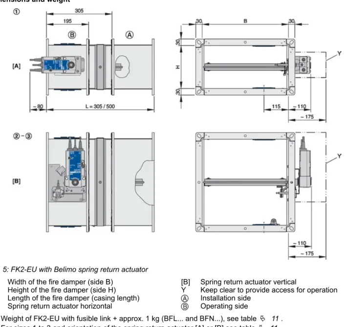
FK2-EU with fusible link
Weight [kg] for housing length L = 305 [mm] / L = 500 [mm] . 1) Design with spring return actuator: [A] = horizontally mounted spring return actuator, [B] = vertically arranged spring return actuator.

FK2-EU with spring return actuator
H Fire damper height (side H) FL Fire damper length (casing length) [A] Horizontal spring return drive. For more information, see the additional instructions for use of explosion-proof fire dampers type FK2-EU.
FK2-EU with spring return actuator and
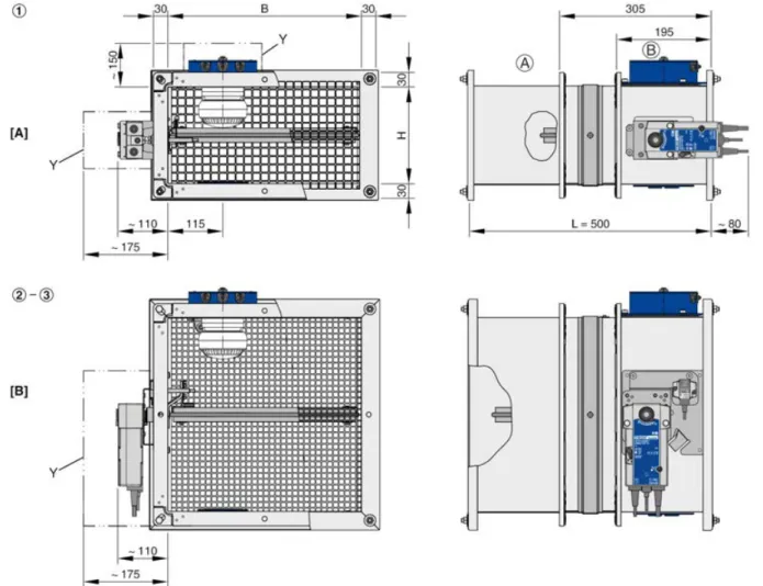
FK2-EU with fusible link and cover grille
FK2-EU with spring return actuator and
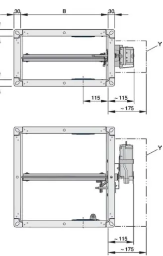
B Fire damper width (B side) H Fire damper height (H side) FL Fire damper length (case length) [A] Horizontal spring return actuator. Install the RM-O-3-D smoke duct detector at the bottom opening of the inspection entrance and at the top when installing the fire damper. For technical details of the duct smoke detector, see the RM-O-3-D operation and installation manual.
In this case, the duct smoke detector must be mounted at the top right, left or center in front of the cover grate, see. If accessories and accessories are supplied from the factory with the fire dampers, they are already taken into account in the order code. Depending on the installation situation, additional materials for assembly and fastening may be needed to ensure correct assembly, e.g.
Operating instructions (1 per shipment) Shades of the damper blade The damper blades are treated with a greenish impregnating agent. The resulting shades of color on the damper blade are due to technical reasons and do not constitute a defect of any kind.

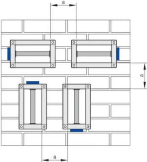
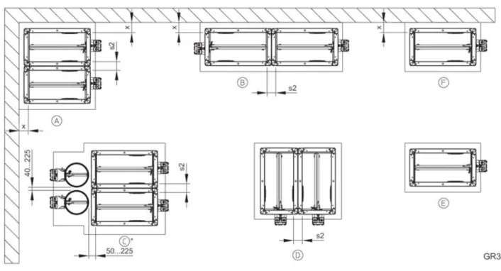
Installation situations
Safety notes regarding installation
General installation information
The fire damper flange can be used for equipotential bonding; holes must not be drilled in the flap housing. In the event of a fire, the loads from the equipotential bonding must not affect the fire damper. The fire damper can be installed so that the damper shaft is horizontal or vertical.
Cover all openings and controls on the fire damper (e.g. with plastic) to protect them from contamination. With mortar-based installation, it may be necessary to protect the sides of the fire damper against deformation, e.g. For mortar-based installation, the open spaces between the fire damper housing and the wall or ceiling slab must be sealed off with mortar.
If you are installing the fire damper while the solid wall or ceiling panel is being completed, you must perimeter. The open spaces between the fire damper and the wall must be sealed with mortar; for installation in fixed ceiling panels, use concrete. Attach (flange) the fire damper to a sheet steel channel that has been shortened and is flush with the wall or ceiling.
Attach the fire damper to sheet steel ducts with fire-resistant cladding and without any openings. Wall or ceiling attachment, wall or ceiling penetration, suspension of the fire damper and attachment of the cladding to the installation kit must be carried out as described in this manual. Attach the fire damper to sheet steel ducts with PAROC® mineral wool insulation and without any openings.
Wall fixing, wall penetration, fire damper hanging and fixing of mineral wool insulation to the assembly kit must be carried out as described in this manual. Provide each installation opening and cut the hole according to local and construction conditions and according to the size of the fire damper. Provide each mounting opening in accordance with local and construction conditions and according to the size of the fire damper.
Solid walls
General
Mortar-based installation
Lightweight partition walls
General
Compensation measures, especially regarding large installation openings (such as for multiple installation), must be determined on a case-by-case basis (by others).

Dry mortarless installation with installa-
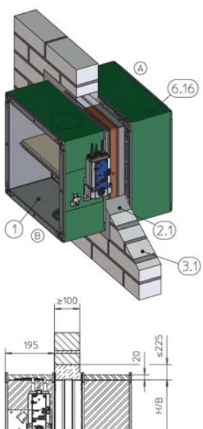
Distance between the fire damper and adjacent structural elements, etc. (depending on the location of the brackets). 65 – 70 mm distance between the fire damper with shortened mounting kit and supporting structural elements, see fig. For wall thicknesses > 100 mm, 2-layer cladding panels (2-layer cladding panels on three sides when mounting near the ceiling) ) can be used as an alternative to the rear closure from 6.2 and 7.14.
Place the fire damper in the center of the installation opening and fasten it to the metal frame with drywall brackets and screws, see picture.

Dry mortarless installation with fire batt
Fixing the fire damper
General
Suspending fire dampers installed
Fixing the damper when a fire batt is
Installation of the fire damper in vertical ducts with a fire rod from EI 90 S requires that the fire damper be fixed both above and below the ceiling plate, see Fig. The fire damper should be suspended along the shorter sides of the cage if possible. When installing adjacent to a solid wall, fixing steel brackets to the solid wall is also permissible.

General safety notes
Limit switches (fire dampers with fusible
Spring return actuator
Spring return actuator – BFL... / BFN