Up-to-date lists and bibliographic references relating to such national standards may be obtained on application to the Central Secretariat or any CENELEC member. The text of the international standard IEC was approved by CENELEC as a European standard without changes. Ultrasonic procedure ..1 7 Appendix B (informative) Example of a simplified cleaning procedure for a test cell ..1 8 Appendix C (informative) Alternative procedures for routine dielectric dissipation testing.
It is the user's responsibility to establish appropriate health and safety practices and determine the applicability of regulatory restrictions prior to use. This International Standard describes methods for determining the dielectric dissipation factor (tan δ), relative permittivity and d.c. IEC 60250, Recommended methods for the determination of permittivity and dielectric dissipation factor of electrical insulating materials at power, sound and radio frequencies including meter wavelengths.
IEC 61620, Insulating liquids - Determination of the dielectric dissipation factor by measuring conduction and capacitance - Test method. The capacitance Ca of the configuration of electrodes in air can normally be used instead of Co to determine the relative permittivity with sufficient accuracy. The loss angle is the angle by which the phase difference between the applied voltage and the resulting current deviates from π/2 rad when the dielectric of the capacitor consists only of insulating material.
Permittivity, tan δ and resistivity, either separately or together, are important indicators of the intrinsic quality and degree of contamination of an insulating liquid.
Permittivity and dielectric dissipation factor (tan δ )
NOTE For practical purposes, measured values below 0.005 for tan δ and power factor are essentially the same. These parameters can be used to interpret the deviation from desired dielectric properties and the potential impact on the performance of equipment in which the fluid is used. Since the initial value is believed to be representative of the actual conditions of the liquid, it seems most desirable that tan δ should be measured as soon as temperature equilibrium is reached.
The procedure described below allows the test specimen to reach temperature equilibrium with the test cell in the shortest possible time.
Resistivity
Sequence of determinations
Factors leading to erroneous results
Standardized procedures for the storage and transfer of the liquid samples and for the construction and cleaning of test cells are recommended so that errors caused by contamination are minimized.
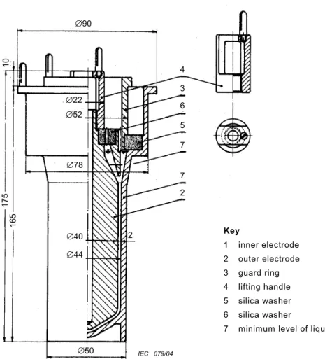
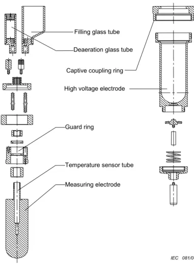
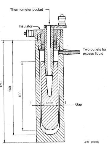
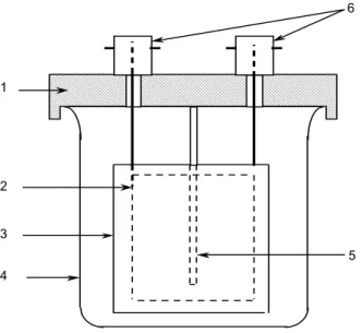
Test cell
For cells with two terminals, the shield on the conductor, which is usually connected to the protective electrode, must be securely attached to the insulation of the cable to prevent contact with any other surface. When these cells are used for resistance measurements, the resistance across the insulators when the cell is empty should be found to be at least 100 times greater than the resistance measured through the liquid. For highly insulating fluids, additional losses due to the insulators supporting the electrodes can alter the measurement.
For this reason it is recommended to use test cells in which there is no bridge made of solid insulating material between the two measuring electrodes. To minimize the effect of contaminants on the surfaces in contact with the liquid, it is recommended to use cells with a low electrode surface area to liquid volume ratio (e.g. < 5 cm–1).
Test equipment...................................................................................................... 1 0
Before the next test, the cell must be flushed with a volume of the next sample corresponding to at least three fillings of the cell. Abrasive particles and rubbing should be such that they do not cause deterioration of the smooth finish of metal surfaces. Drying time depends on the design of the cell, but usually 60 minutes to 120 minutes is satisfactory to remove any moisture.
Sufficient space must be left for the expansion of the liquid to avoid breaking the container. Rinse the cell three times with a portion of the oil sample, filter and discard the liquid. The measurement must start within 10 minutes of reaching a temperature within ±1 °C of the required test temperature.
Great care must be taken to avoid contact of fluid or cell parts with any source of contamination. Where the cells are not automatically heated, carry out the dispersion factor measurement within 10 minutes of reaching a temperature within ±1 °C of the required test temperature. Report the dispersion factor (tan δ) of the sample as the mean of two valid measurements.
Cn is the capacitance of the cell filled with the calibration liquid with the relative permittivity εn;. Measure the capacitance Cx of the cell filled with the liquid under test and calculate the relative permittivity εx from this. Repeat the test until two consecutive readings do not differ by more than 5% of the highest value.
A second measurement at each charge, made with the polarity of the applied voltage reversed, can provide information on cell purity and other phenomena. Drying time depends on cell design, but 60 to 120 minutes is usually sufficient to remove moisture. Test cells modified to allow fluid replacement without opening the cell may also be used.
The actual drying time depends on the cell design, but 60 min to 90 min is usually satisfactory to remove any moisture. If the value of the last sample tested is worse than the specified value, the test cell must be cleaned before it is used for further tests. When the liquid is not heated in the cell, the reading should be taken after a residence time in the cell of 10 min to 15 min and when the internal electrode temperature is within ±2 °C of the specified temperature.
IEC Insulating liquids - Determination of the dielectric dissipation factor by .. measurement of the conductivity and capacitance - Test method.