Application for Conditional Use Permit
Texpar Energy LLC 1804 7th Street NW Rochester, Minnesota
Submitted to:
City of Rochester Planning and Zoning
May 2018
TEXPAR ENERGY, ILC
ADMSIONOFPE'I'RO ENERGY 92010THAVENUE NORTH 0NAIASKA, WISCONSIN
54650
Table of Contents
CONDITIONAL USE PERMIT APPLICATION
1.1 PURPOSE 1
1.2 LOCATION AND BACKGROUND 1
1.3 PROJECT DESCRIPTION 2
1.4 ENGINEERING APPROVAL FOR WALL DESIGNS 3
1.5 PROPOSED CONSTRUCTION SCHEDULE 3
1.6 WATERWAYS AND WETLANDS 4
1.7 EROSION CONTROL 4
FIGURES
FIGURE 1 SITE LOCATION WITH FLOODPLAIN MAP FIGURE 2 SITE INFORMATION WITH EASEMENTS
FIGURE 3 PROPOSED SITE PLAN - PLAN VIEW (FOR BERM MODIFICATION ONLY)
FIGURE 4 WETLAND MAP
ATTACHMENTS
ATTACHMENT A LAND DEVELOPMENT APPLICATION FOR CONDITIONAL USE PERMIT
ATTACHMENT B ENGINEERING APPROVAL FOR WALL DESIGNS
CONDITIONAL USE PERMIT APPLICATION FOR TEXPAR ENERGY, LLC
1.1 Purpose
The purpose of this Conditional Use Permit (CUP) application is to gain City of Rochester approval for modification of the containment berm located in the floodplain district. Because the subject property was annexed into the City of Rochester before 1980, the flood elevation outside of the flood way is classified as Flood Fringe, defined by the Rochester Zoning Ordinance in Section 62.800. Alteration of the existing containment berm, as it relates to flood control,
requires conditional use approval, but does not require floodplain mitigation. See Attachment A for the completed Land Development Application for a Conditional Use Permit.
Additional proposed site development, outside of containment berm alteration, will be submitted to the Planning and Zoning Department separately as a Type 1 Site Development Plan.
1.2 Location & Background
The Texpar Energy- Rochester terminal is an active storage tank terminal comprised of 3 parcels within the City of Rochester. Two of the parcels, totaling 8.32 acres and adjacent to U.S. Highway 14, include the existing storage tanks and proposed loading and unloading facilities while the
3rdparcel, totaling 1.24 acres, lies along
7thStreet NW. The current
7thStreet NW parcel contains the inactive loading rack and associated office. The parcels were purchased in 2003 from the previous owner and underwent additional tank construction in 2007. Figure 1 depicts the Site Location, including parcel information and floodplain depiction. Figure 2 depicts Site Information including easements.
ester 0
C;~
~
tf' RECEIVED ~
(.\)
AY 3 0 2018
o..Contact information for the owner, operator and structural engineers are as follows:
1.3
Owner & Operator
Texpar Energy, LLC (Contact: Tara Wetzel) 920 1
othAve. North Onalaska, WI 54650 (608) 779-6322
Email: tara. [email protected]
Structural Engineer - Retaining Wall
David D. Holstrom Construction Express Inc.
411 La Crosse Street La Crosse, WI 54601 ( 608) 784-9290
Structural Engineer - Sheet Piling
Westbrook Associated Engineers, Inc.
619 East Hoxe Street Spring Green, WI 53588 (608) 588-7868
Project Description
CUP Process Description: This CUP application describes the proposed modification to the existing containment berm, which is considered a flood control structure within the floodplain.
See Figures 3-1 and 3-2 for the Proposed Site Plan. The modification of the existing containment berm is necessary to accommodate the tanker trucks for the relocated loading rack on the southern portion of the property. The berm modification includes removing part of the containment berm and replacing with a retaining wall constructed of sheet piling to increase the available space for the tanker trucks to maneuver and tum.
Site Development Description
(notincluded in this application): The proposed project includes relocating the existing loading rack structure, associated piping and truck scale from the
7thStreet
2
parcel to the south parcels along U.S. Highway 14. The truck access to the relocated loading facilities is via a 1976 site access easement originating from the frontage road along U.S. Highway 14.
The planned stages of the entire project are as follows:
1. Installation of the downgradient erosion control as listed in the approved grading plan.
2. Installation of the sheet piling and retaining wall, berm modification and associated site grading.
3. Relocation of the loading rack and truck scale along with construction of the associated above ground piping between the loading rack and storage tanks within the containment berm.
4. Construction and placement of the service building.
5. Seeding and landscaping.
1.4 Engineering Approval for Wall Designs
David D. Holstrom, P.E., from Construction Express, Inc. has stamped and certified the retaining wall design per engineering standards for both flood control and berm containment design.
Westbrook Associated Engineers, Inc. has certified the sheet piling design per engineering standards for both flood control and berm containment design. The stamped drawings and associated calculations are in Attachment B.
1.5 Proposed Construction Schedule
Construction for the site will begin as soon as the pertinent approvals are granted by the City of Rochester. Texpar Energy is working concurrently with state and federal agencies for additional necessary approvals and permitting.
3
1.6 Waterways and Wetlands
An unnamed branch of Cascade Creek is located east of project site along with adjacent wetlands.
See Figures 1 and 4 for the location of the waterway and wetlands. The project will remain outside of those areas and will not impact either the described waterway or wetland structures.
1. 7 Erosion Control
Silt fencing will be utilized downgradient of all disturbed areas per the approved grading permit submitted separately to the Planning and Zoning office. Once the grading activities are
completed, seeding and landscaping per the approved grading permit will be completed.
4
Figures
STORAGE TANK
FIGURE 1 SITE LOCATION WITH
FLOODPLAIN MAP
•
TEXPAR
l!N l!RGV
TexPar Energy, LLC 1804 7th Street NW Rochester, MN 55901
N 0
A
5 100 200 FeetSTORAGE TANK
24' RAILROAD CROSSING AGREEMENT CHICAGO GREAT WESTERN RR1& CITY DATED 3/11/1968
SITE INFORMATIC WITH EASEMEN"
•
TEXPAF
ENERGY -
TexPar Energy, LI 1804 7th Street N Rochester, MN 55
Sheet Pile Wall
. 1. g Berm
f· ~ /l eve Ex1s m
~ Rem
Property Boundary
. Contour 1000' Elevation
. Contour 1005' Elevation
. Contour 101 O' Elevation
Contours Shown are 1ft Elevation Changes
expar Energy' N LLC 920 10th Ave.
WI 54650 Onalaska,
Condition?I Use Permit Texpar Energy, W LLC
1804 7th ~~ ~5901
Rochester,
TEXPAR
pril 19, 2018
'5' ~
cf RECEIVED
d\~0..
1:1,720
0 0.0125 0.025 0.05 mi
I
I I I I,
I I I I'
I' ,
I0 0.0225 0.045 · 0.09 km
Olmsted County is not responsible for omissions or errors contained herein.
MAY 3 0 2018
..., Rochester-Olmsted Planning Dept. GIS Division
c;::.
1J
Rochester-Olmsted County Planning Depl GIS Division, Rochester Pu~ ~ Utilities and Rochester Public Works Dept.
~
S'
Rochester-Olmsted County Planning Depl GIS Division.;1..,,.A ~.::,.
If discrepancies are found within this map please notify the GIS Division at (507j'3~ ~R~ ~er-Olmsted Planning Department, 2122 Campus Drive S.E.. Ste. 100, Rochester, Minnesota 55!
Attachment A
Land Development Application for the
Conditional Use Permit
r
57'-6"
/ GENERAL NOTES
~ Sheet Pile Wall
i - - - -408'-11"- - - t
- Grade Behind Ret. Wall
32'-7"
Steel Sheet Wall
Concrete Retaining Wall · - ~
Approx. Excavation Elevation
- 0100 +1ft Flood Elevation
*Dimensions Are Approximate, Final location& dimensions to be submitted
upon project completion*
'"No. Revison/lssue Date,)
OWNER:
expar Energy, LLC 920 10th Ave. N Onalaska, WI 54650
11111111111111111111111111m1111111111111111111111111111111111111111111111111111111111111111111111111111111111111110011111111111111111111111111111111111111111111111111111m111111111111111111
PROJECTConditional Use Permit
Texpar Energy, LLC
~ester
O 1804 7th St. NW Q:o
0RECEIVED\ Rochester, MN 55901
c "' r 3 o 201a ~ a.
/DRAWINGAttachment B -: SHEET:
""
Sheet Pile Wall
(.\) 't7
~
lb'~~
vv
O'ao 5u\
DATE:
1
5/29/2018
SCALE:
'"
NA ,)PRELIMINARY STRUCTURAL ANALYSIS AND COMPUTATIONS
FOR
~
'\efeREI\NAN
J.F. BRENNAN COMPANY, INC.
TEXPAR ENERGY SHEET PILE WALL
Tms
PLAN SUBMISSION IS FOR PROJECT PERMITTING AND REVIEW ONLY. NOT FOR CONSTRUCTION. FINAL DESIGN PLANS AND SPECIFICATIONS ARE REQUIRED PRIOR TOCONSTRUC~
~ ' · ~
~~~':,·c:.s c-c to
~N s /~
i.A.~~
.. r
~~ ~
~ ~
§r:?
ANDREW C.{!"%
=
KNUTSON=
~ E-34662
i
'§ "O SPRING GREEN ~ ~
~ :-::::,0 .,, WI I
/;'!
':'Y:-.; ~~ ~ S'".Jo•1t3 ~ ~
~ (C'~
o"'
~~~1, 810NAL
E..~ ~,,~~
'/Ji,,,,,,,11111111111\\\\\\''''"
Prepared by
WESTBROOK ASSOCIATED ENGINEERS,
INC.
WESTBROOK
Associated Engineers, Inc.
619 East Hoxie St.
Spring Green, Wisconsin 53588 Phone: (608) 588-7866
Fax: ( 608) 588-7954 WAE#l8087
MAY2018
Associated Ennineers, Inc. TITLE: TEx PA~
PROPOSED PZC-18 SHEET P I L I N G ~
EXISTING BERM \ \
\ ' -=11 '2..l~lll=/=ill1 ,
-111311~ffi~L l=- -==:111~ ~111:=111-
'i;:;:l.ll:=111-
::, u
SECTION A
EXISTING BERM \ PROPOSED PZC-18
SHEET PILING \
- n~=~=wr=~ffi~11~=w1 ~1~1
1 1
__:11 E4m~illmillmillm==ITT==111--ITT~w:Mm~u...
=lL-' i:::1
IT==m ==111=-
1, • 1 11-:1 1 1==1 11==111==1 1 =---..
-+---,,.-= :::::\
il~ J
I l::::TTI=.-1· ' _,''=I I~=ill.
l\~lll=lii='' -111:::;i\
::111=
1'SECTION B
;n I
0 I
"
~ EL 1012.00 _) TOP Of SHEET
~ ~~ 1~1·~~RM
EL 1001.00 SOIL EL IN FRONT OF WALL
~ EL ±1000.00 EXISTING LOW SOIL
~ EL 987.oo MIN. TIP
~ ~~p 1g~1:RM _J ~ ~ 1g~e~om
~~~O~~TION
EL 1001.00 SOIL El. IN FRONT OF WALL
~&\s~~~~~
SOIL
No. Oc:c By
- - - - 619 EAST HOXIE smm
.,.- " ' - P.O. BOX 429
WESTBROOK
:n:!;·s:_.5.,:
Rs::ociat~d Engineers, Inc. FAX (608) 588-7954
RETAINING WALL FOR TEXPAR ENERGY, LLC 1804 7TH ST. NW ROCHESTER, MN 55901
WAf.f 18087
RETAINING WALL SECTIONS
SHEET 3 OF 3
LOG OF TEST BORING
PROJECT NAME: Texpar CLIENT/WSB #: 011450-000
PROJECT LOCATION: Rochester, MN SURFACE ELEVATION: 1006 ft iDEPTII ELEV.
(ft) (ft)
1-,_ 1005
DESCRIPTION OF MATERIAL FII..L, mostly Sandy Lean Clay, brown and dark brown, moist
6-t- 1000 ~ ) . . a ) . . a ) ~ - - - 1 ORGANIC CLAY, black, wet lo moist, very 7--999
·-
8-.-998 9--997
....
- -
....
....
....
-
....
-
....
- - -
....
....
- -
.... ....
1,,, - -J' ~ -
12-.-994 13--993 14---992 15-,-991 16-1-990
:\·. ;:
:.· .....
:·:·
\: : .:
\: :: .
):
..\: :. ;:
\
.·.·:. :·
..:):.:
:. · ...
soft to soft
SAND WITH GRAVEL AND A LITTLE SILT, fine to medium grained, brown, wet to waterbearing, medium dense
uses
SP-SM
18- >-988 ::\. :.J. ·: .. .1 1 - - - 1 - - - - 1 . SAND WITH A UTILE SILT AND GRAVEL, .fine to medium grained, brown,
waterbering, medium dense
SP-SM
19-~987 20--986 21- >-985 22->-984 23->--983
:,
... . ::.:: :.:·
:. · ...
End ofBoring 21.0 ft.
GEOLOGIC ORIGIN
Fill
Topsoil
Coarse Alluvium N
18
8
4
11
20
22
16
LABORATORY TESTS ...J SAMPLE
MC DD LL PL No. TYPE (%) (pcf) (%) (%)
~
HSA
2 SB
3 SB
4 SB 106
~
5 SB
'SJ_
6 SB
7 SB
8 SB
g
24--982'1---..---...---W_A_TE_R-,-LE_VE_L_MEA_,--s_URE_ThIBNT---T __ s _ _ ---,---+--ST_AR_T_:_11_24_12_0_1_8...---''-END _ _ :-,J/.-2_41_20_1_8 _ _ _ - - - i
<!> SAMPLED CASING CAVE-IN WATER WATER Crew Chief:
I
Logged By:g DA TE TIME DEPTII DEPTII DEPTII DEPlli ELEVATlON METIIOD R. Kurth
I
MWOi1-1-/2-4-/2_0_1_8-+--12-:-l5_p_m--+--2-1----i'----19-.-5-1---1--l-2-.0--+----9-9-4----+-3-1 /_4_H_S_A_O_' ___ J_9.-5'+-N-ot-es_: _ _ _ __..___ _ _ _ _ _ --4
g 1/25/2018 1:00 pm 8.5 997.5
ll'.ll---+----'--f---11---+---4----=----1----:.__---+---~
~---_ ... __
_..__________
...______
..____________
____.I
I .
....
0
ao
i
... .
W$8
,-:;&=AYI;;:;;•Min::.;.;.;"''·J~,:,·. _ _ _ _ _ _ _ _ _ _
L_ O _ G _ O_ F_ T _ E _ S _ T_ B _ O _ RIN __ G _ _ _ _ _ _ _ _
.,WJMlf1~1....;;j;._o_i_o_iij--.:1J~
ii)
PROJECT NAME: Texpar CLIENT/WSB #: 011450-000
PROJECT LOCATION: Rochester, MN SURFACE ELEVATION: 1007 ft IDEPTil ELEV.
(ft) (ft) DESCRJPTION OF MATERIAL
\ ' ) Fil.l.., mostly Sandy Lean Clay, brown and gray,
~~ ~ moist 1 - ,-1006 }<) ':><
b )-, ))
C ~ ~ 2 - ,_ 1005 b) , )
)
'
))
'
))
'
)3-1-1004 ) ~
4-'-1003 ~, )
._ ORGANIC CLAY, black to gray, moist to wet, 5---1002 ... - - soft
,_ - 6---1001 ~
-
-8- 1--999 9- >-998 10- ... 997 ,,
...
-,_ -
- -
,_ - -
,_ -
-
,_
-
...
.... -
.... -
-12- 1-995 :.-..
14-1--993 15- >-992
17- -990 18- >-989 19- --988 20--987
22- ,.._985
...
: :.~:
.. ..:. · .. '
::.~:
..(:·.
\: '
.. .. .:.··:.
::} .
:
..:.· ... :<· . .'. ~:
:. · ...
: : . ~ :
.:
.SAND WITII SILT AND GRAVEL, fine to medium grained, gray to brown. wet to waterbearing, medium dense
A \JtRP\Gt N~ \i.G<o
End of Boring 21.0 ft.
uses
OL
SP-SM
GEOLOGIC ORIGIN
Fill
Topsoil
Coarse Alluvium N
8
7
5
10
18
24
14
BORING ~ TMRER PB- ~
~~:;: ; GE 1
w Y
SAMPLE LABORA JI rn r-l .t.STS
~ MC DD Ll... PL
No. n'PE (%) (pcf) (%) (%)
1 I-ISA
2 SB
3 SB
4 SB
.!. 5 SB 34
6 SB '¥-
7 SB
8 SB
24- >-983 b (!)
l:t---_.._ _
_ . . . _ _ _ _ i _ _ _ _ _ _ _ _ _ _ _ _ _ _ _ _ i _ _ _ _ i _ _ ~ _ _ _ . _ _ _ . . _ _ _ _ . _ _ _ _ . _ _ ~ L - - - ' - - L - - - L - - - t - - - 1WATER IEVEL MEASUREMENTS START: 1/24/2018 jEND: 1/24/2018 Crew Chief: j Logged By:
DATE TIME SAMPLED CASING CAVE-IN WATER WAT.ER METHOD
(!)
DEPTH DEPTH DEPTH DEPTH ELEVATION R. Kurth IMWO.
1/24/2018 1:15pm 21 19.5 14.0 993 3 1/4 HSA O'-19.5' Notes:
g
~ t - - - + - - - + - - - - + - - - + - - - - + - - - + - - - + - - - + - - - _ _ . . _ - - - 1 ii: 0
al
al 1/25/2018 1:00pm 10.5 996.5
~
. ... __
_.___
__.,____
..___
_.___ ... ___ ... _____ _.. _____
__.___________
__.. f \J
AV
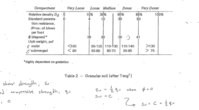
F f\c_ \So_il Properties - Independent of the theory used _to compute ear~ pressure on retaining structures, the results can be no more accurate than the soil prope~ies used in the calculations. Because of the wide variations of subsurface condition? at various sites, the soil constrnts s·hould · be determined on the basis of an exploratory boring program and laboratory tests of representative sarnples. Only th~n can a safe and~economical design be assured. H9wever, for the purpose of preliminary design it is often necessary to ! presume appropriate soil properties. The followit"}g tables and graphs are included for this · purpose merely as a guide.
Table 2 shows an approximate relationship between the relative density, standard penetrc1tion ·resistance, angle of internal friction, and unit weight of granular soils.
Compactness Very Loose Loose Medium Dense Very J?ense
I I
3~%
I I
1do%
Relative density Da 0 I 1y% I 65% 85%
3'o
IStandard penetra- 0 4 10 50
tion resistance, N=no.- of blows
per foot
<p (degrees)* 28 30 36
-J
41U~it weight, pcf
'{: moist <100 95-125 110· 30. 1.10-140 >130
t.i"' • submerged
<
60 55-65 60-70 65-85>
75... highly dependent on gradation .
Table 2 - Granular-soil (afterTeng1} J V\.d~N~
~J~""" s~\."t:l'" , s~ ·
l
\_)V\c..o\'°'t\r----J . w:; w-r~rtss-.\re.. s.\..rt~ _\.l., • °(,J S-.:i -=- 2.
'\,<.l
v-l\--tV\ cf> = ()5'-' -::: C-
(.4' \tt....e $ io,/\ I C.
~ s.) ;:::.
C ; .i.'f-J
Ta~le 3 shows an approximate relationship between the unconfined compressive strength, standard penetration resistance and the unit weight of cohesive soils .
12
Consistency
qu =< unconfined
compression strength, tdns per square ft Standard penetra-
tion resistance, N-=no. of bt'ows
per ft Unit weight, pcf
{:x3turated)
Identification characteristics
: ..
Very Soft Soft ·_.Medium Stiff Very Stiff Hard
0 0.25 0.50 1.00 2.00 4.00
.• '·
,, I · ,
I I I
0 2 4 -8 16 32
l
I
100-120 110-130 120-140 130+
Exudes Molded Molded Indented Indented Difficult from by lig.ht by strong by thumb
between finger finger fingers pressure pressure whel)
squeezed in hand
by thumb to indent
e'b\e r oi .
nail by thu'ti(' · ~
nail
rf RECEIVED U't
y 3 O 2018
*" tJ
C::...
tI;""
~ -0
... ~ -.)
,. "l..;8
da t>\).'.
. 0 -
Table 3 - Cohesive soil (after Teng1)
I ~ .
Client: JF Brennan litle: Texar Energy Site Designer: AJM
Page: 1 Date: 5.29.18 Sheet: PZ35 Pressure: Coulomb
Toe: Cantile\er
if@i~;r{,Maxirou r.n:if\MfQ.
:~at,(rt):f'.1 o 746.2psf 10.00 D 36507.9ftlb/ft 16.74• 1.1in 0.00
ester 0
~ ~
cf RECEIVED %
AY 3 0 2018
0-Westbrook Associated Engineers
#JJJ]f v
0.00 ft
15.00 ft
23.74 ft
SPW911, v2.40
C 2001- 2007, Pile Buck!!), Inc.
Errail: pilebucl<@pilebuck.com
\llkb: www.pilebuck.com
_]
Client: JF Brennan Title: Texar Energy Site Designer: AJM
Page:2 Date: 5.29.18 Sheet: PZ35 Pressure: Coulomb
Toe: Cantilever
Input Data
Depth Of Excavation= 10.00 ft Depth Of Active Water= 4.30 ft Water Density = 62.43 pcf Minimum Fluid Density= 31.82 pcf Surcharge= 240.0 psf Depth Of Passive Water= 12.00 ft
Soil Profile
: ~~etffY (~~ ·:$ ~ p~f;'. : ~~~~::
!'2cr,,· ..0.00 Sandy Clay 15.00 Dense Fine Sand
Sheet
Maxima
Bending Moment Deflection Pressure Shear Force
36507.9ftlb/ft 16.74 ft
1.1in 0.00ft
746.2psf 10.00 ft 4409.1 lb/ft 11.95 ft
; ' {ii~nt ~ 1 S t ~s u * ~ ? (rim : G iR~s~ r mt~ ) } ; ~ ; c~ ; H <~i;~ ~iK~r (·~$~;
JJ§~~120.00 57.60 0.0 0.0 25.0 15.0 0.36 0.00 3.85 0.00 120.00 57.60 0.0 0.0 34.0 15.0 0.26 0.00 6.19 0.00
Solution
- - y - - Sttr !G
Westbrook Associated Engineers SPW9 11
1v2.40
.. n
4:> 2001 • 2007, Pile Buel®, Inc.
Errail: pilebucl@pilebuckcom 111.t!b: www.pilebuckcom
Client: JF Brennan Title: Texar Energy Site Designer: AJM
Page: 3 Date: 5.29.18 Sheet: PZ35 Pressure: Coulomb
Toe: CantileWJr
)tj1itJ~1~16.:fµro:ir!f1!? ,:11~ 1 t~I:\'.i
o 746.2psf 10.00 D 36507.9ftlb/ft 16.74 0 4409.1 lb/ft 11:95
• 1.1 in 0.00
Pressure (psf)
-5 -4 -3
I 1 1
-2 -1
I I
~---;---r---T---,---
1 I I I I
I I I 1 1
1 I I I
I I I I I
1---4---1---+---1---
I I I I I
1 I I I
I I 1 I
1 I I 1 1
~---l---1---.l---...1---~
I I I 1 I
1 1 1 I
I 1 1 1
.1 1 1 1
L ______ J _______ L _____ - - - ~ - - - - -
! I I 1 I
I I 1 I I
I I I I
I I I
I I I I I
1 - - - - - I - - I 1 I -
I I I I I
I I I I
I I I I
I I I I 1
---
Deflection (in) 0
X 103
0 1
I I I
______ J I I I I I
---,
Id(ft)
I I I I
2
I I 1
I I
- . T---1
I I
I I
I I
---+---!
I II I
I I
---L---J
I II 1
I I
I l
___________________ 1 _____________________ J
I I
I l
I I
I I
I I
- - - , - - - I
I l
1 I
I l
2 ---~---~
d(ft)
Bending Moment (ftlb/ft)
0 4 8 12 16 20 24 28 32
X 103 36 40
I I I
4 --~----~---~-- --:--- -~---~--- - ~- --~ ----~ - - -~
I I I I I I I I I
I I I I I I I I I
I I I I I I I I
I 1 I I I I I I I
8 l---+----l----l---1----l---l-- - -1-----l
I r I I 1 r
I I I I I I
I I I I 1 I
1 1 r I I I I 1 r
12
----l----1----.l- ___ ,____ --'----'--
---l----1---l1 I I 1 1 I I 1 I
1 I I I 1 I
1 I I I 1
1 I I I I I I I I I
16 ---{----~--
-t----:----}---~----}---~ ---- ---
~1 1 I I I I I I I
I I I I I I I I
I I I I I 1
20 : : - : I - : 1- - : - - - :-- - : - - -J
1 I I I I I I
I I I I
I I I I
- - - ' ___ I ____ I ____ I ________ 1 - - - 1 ____ 1 - - -I
Shear Force (lb/ft) -3 -2 -1
I I I
I I I
~----,---r---4
I I
1 I
I 1 I
1---1---+---8
I 1 I
I I I
I 1 I
I I I
L----~---L--~~
I I I
I I
I I
I 1 I
~----~---}--~~
r 1 r----
1 I
I I
I
0 2
I I 1
3
X 103
4 5
I I I 1 I
-T---r----;---~----1
I 1 I I
I 1 1 I
I I I
I 1 I
--4---1---1
I I
1 I
1 __ J I
I
I - - - - 1 _____ I ---2; - - - - d(ft)
Westbrook Associated Engineers SPW911,
Q 2001 -2007, Pile Buck!!), Inc.v2.40
Email: [email protected]V'kb: www.pilebuck.com
Client: JF Brennan Title: Texar Energy Site Designer: AJM
Page:4 Date: 5.29.18 Sheet: PZ35 Pressure: Coulomb
Toe: Cantilewr
113.8 122.3 131.7 141.1
1.9 7.6 18.6 33.2 54.8 82.6 149.7 113.7 159.1 154.7 168.5 203.2 177.0 254.2 186.4 318.2 195.0 384.1 204.4 465.4 213.8 556.3 222.3 647.8 231.7 758.4 241.1 880.0 249.7 1000.4 259.1 1144.1 267.6 1285.4 281.5 1452.9 299.6 1633.7 316.1 1810.4 334.2 2019.0 350.6 2222.3 368.7 2461.8 386.8 2718.8 403.3 2968.2 421.4 3260.8 439.5 3573.3 455.9 3875.4 474.1 4228.4 490.5 4568.6 508.6 4965. 1 526. 7 5385.6 543.2 5789.5 561.3 6258.3
1.1 1.1 1.1 1.1 1.0 1.0 1.0 1.0 1.0 1.0 1.0 0.9 0.9 0.9 0.9 0.9 0.9 0.8 0.8 0.8 0.8 0.8 0.8 0.7 0.7 0.7 0.7 0.7 0.7 0.7 0.6 0.6 0.6 0.6 0.6 0.6
613.9 7776.0 630.4 8299.6 648.5 8904.1 666.6 9539.3 683.0 10144.1 701.1 10840.1 717.6 11501.7 735.7 12261.8 711.7 13056.6 636.7 13808.3 554.2 14663.9 471.8 15545.6 396.8 16366.7 314.4 17287.6 239.4 18137.9 156.9 19083.8 74.5 20037.2 -0.5 20907.0 -49.4 21864.0 -93.1 22818.9 -132.9 23683.3 -176.7 24628.3 -216.4 25480.4 -260.2 26408.0 -304.0 27323.6 -343.7 28143.6 -387.5 29030.3 -431.2 29898.8 -471.0 30671.0 -514.8 31499.2 -554.6 32231.2 -598.3 33011.5 -1764.5 33757.3 -1832.1 34369.1 -1906.4 34959. 7 -1974.0 35418.7
0.5 0.5 0.5 0.5 0.4 0.4 0.4 0.4 0.4 0.4 0.4 0.3 0.3 0.3 0.3 0.3 0.3 0.3 0.3 0.2 0.2 0.2 0.2 0.2 0.2 0.2 0.2 0.2 0.1 0.1 0.1 0.1 0.1 0.1 0.1
Westbrook Associated Engineers
-2048.4 35834.9 0.1 1676.8 -2122.7 36154.5 0.1 1223.6 -2190.3 36358.4
-2264.6 36484.1 -2339.0 36497.4 -2406.6 36352.0 -2480.9 36004.9 -2548.5 35530.1 -2622.8 34844.8 -2697.2 34001.7 -2764.8 33109.4 -2839.1 32001. 7 -2913.5 30774.7 -2981.1 29566.9 -3055.4 28148.9 -3123.0 26789.4 -3197.3 25228.8 -3271.7 23612.8 -3339.3 22106.7 -3413.6 20421. 7 -3481.2 18874.8 -3555.5 17169.0 -3629.9 15471.7
·3697.5 13947.1 -3771. 8 12302. 7 -3846.2 10705.2 -3913.8 9304.9 7834.0 6570.7 5274.7 4089.4 3119.3 2182.6 1395.2 820.3 355.0 94.9 -4704.5 0.0
0.1 797.6 0.1 313.5 0.1 -93.3 0.1 -317.3 0.0 -548.3 0.0 -744.2 0.0 -944.3 0.0 -1128.2 0.0 -1281.3 0.0 -1434.3 0.0 -1571.1 0.0 -1681.4 0.0 -1787.3 0.0 -1869.6 0.0 -1944.6 0.0 -2003.5 0.0 -2042.9 0.0 -2070.9 0.0 -2082.2 0.0 -2079.3 0.0 -2060.2 0.0 -2028.7 0.0 -1978.7 0.0 -1912.5 0.0 -1838.3 0.0 -1741.2 0.0 -1639.0 0.0 -1511.0 0.0 -1366.8 0.0 -1221.7 0.0 -1046.7 0.0 -855.5 0.0 -667.6 0.0 -445.4 0.0 -229.5 0.0 0.0
SPW911, v2.40
Q;) 2001 -2007, Pile Buck!!), Inc.
En-ail: pilebucl<@pilebuck.com
\Jlkb: www.pilebuck.com
LBFostea:
Piling
Z Pile Profile
1----WlDlH----+f
-lYl'JCAL PZC 3~
SHEfl PILE SECTION
HEJGHl
J
Cover Plated Z Profile
1
1l ffl
mm in mm in mm in kg/Im lb/ 1ft kg/mlb /ft2 2 cmin4 4 cmin4 4/ /wm wft cmin3 3 cmin3 3/wft /wm n,ft22 / /lm 1ft27.88 12.60 0.420 0.420 55.0 23.7 381.6 164.3 60.5 26.0 5.60
PZC 14
708 320 10.7 10.7 81.8 115.5 15,890 22,440 990 1,400 1.71
,.,. ::,·.-,.c;,,-:·, ,,"'·2s 'oo :(.
'?1.$} il } ·70 J is./\'i
::,:i\p_.3.7~_:'?/S5-Q) 4 ::·.: }:)ii) ::::\ /rs.~t ~ \t · / 2ssls "\s:.:-:: <;'69.1 a >'. \' j is ; \ :}s ~ io:<\·::
; ·,t!. ~}- ~ ?: /).; ~ii,:/'. ?)fi.\ :-::.\9.~ s:> .:\/9.~ s {:.:::r \'1.s) /:;, ?\i 1 : )i;:t-::: :.'.-'2i>1 s.o :
iF ) _ ; ( ~~: <>. -:-:: i /14s.> ;,:,:i f3-0. P. --< :J~ 1f \>"·
25.00 15.30 0.420 0.420 55.0 26.4 576.3 276.6 75.3 36.1 5.60
PZC 19
635 388 10.7 10.7 81.8 128.8 23,990 37,780 1,235 1,945 1.71
27.88 17.66 0.485 0.560 69.4 29.9 938.7 404.1 106.3 45.7 6.15
PZC25
708 449 12.3 14.2 103.3 145.9 39,070 55,190 1,740 2,455 1.87
·" '-"·.'J
/: ~ : f ~ ' f t i:/i>.· : : ~2:s->:' :)9:: ~ : < i ~ .\
:i: /{z3J 9 '_::.> ) j i i::-:> .<:~i4: · f i/ :_;-:.:\4i· j ~ f/'i
:11~;4> '\, ..4(4:i:. , :'·.:tr,~:
t~ ~(M;: . . . " · · · . · · ··· · · ·· ·.·· · ·· · ·. -···-- ··· ··· ·
·:·-;';,.- .: .. :,:,·.·.'-: :::.J7 _ 0.s<: ,>A~Q >>
·:j 3~3'._·.::::,.J:,;_~ ;~ /},.) ·. hio J;r._:: > ,ss)if\ \41 \39. o .C .Js~ ; 4M :v ) ;s.4.0)
·)2;600., ·.:::-_1 r a:, >Y
PZC28 27.88 17.75 0.570 0.645 79.0 34.0 1,057 455.1 119.1 51.3 6.15
708 451 14.5 16.4 117.6 166.1 44,000 62,150 1,950 2,755 1.87
PZC37 22.50 21.02 0.488 0.563 69.6 37.1 1,349 719.6 128.4 68.5 6.15
572 534 12.4 14.3 103.6 181.2 56,160 98,270 2,100 3,680 1.87
::·_:=.i~;1,!1> : -:'1~-~;6 ... :72.3
'\6.1s//.::
22.50 21.09 0.561 PZC41
572 536 14.2
Available Grades: ASTM A572 Gr. 50 and 60, ASBB and A690 +Values stated are nominal
0.636 16.2
"Both sides of sheet excludes socket interior and ball interlock
)i"oM 1 Qo
>:; ~;:i2 f -' . x · a~s90· .:·· . ·;_ : ,) ii?
78.4 41.8 1,507 803.6 142.7 76.1 6.15
116.6 204.1 62,720 109,700 2,340 4,090 1.87 PZC"" is a trademark of Gerdau
PZC 48-CP 86. 7 46.3 42.9 997 89.4
{PZC39) 129.0 226.1 209.5 136,100 4,810
"Excludes socket Interior and ball interlock
, Best economy is obtained when plate length is limited to area of high moment.
• Filet weld should be sized to adequately resist design loads and should be continuous and all around.
• Cover plate length depends upon bending moment curve.
• Weld requirements should be specified by design engineer.
Available Grades: ASTM A572 Gr. SO
lo
r
i.
20' 11 I
60'
/
GENERAL NOTES
D
Concrete Retaining Wall - - Grade Behind Ret. WallApprox. Excavation Elevation
ester 0
o"' ~
oP RECEIVED ~
ro MAY 3 0 2018 o.
*Dimensions Are Approximate, Final location& dimensions to be submitted
upon project completion*
\.. No. Revison/lssue
Date_)
OWNER:
expar Energy, LLC 920 10th Ave. N Onalaska, WI 54650
PROJECT:
Conditional Use Permit
Texpar Energy, LLC 1804 7th St. NW Rochester, MN 55901
/DRAWING: SHEET: -...,
Attachment B - Retaining Wall DATE:
5/29/2018
1
SCALE:
\..._ _ _ _ _ _ NA -1..,. _ _ _,,,_)
•
- Member of The American Institute of ArchitectsPROJECT:*-180 l\ - TE.X fAF,, E.Nf.R.EJ'(
DATE:
MA'1 2',
1
2.01e, ev: HeL,?1'(3-offi
Re:
f?1f!vG-TvW?Ak CALc1JL.AT1otJs
CONSTRUCTION EXPRESS INC
411 LA CROSSE smEET LA CROSSE WI 54601
(608) 784-9290 FAX (608) 784·9396 PAGE _ \ _ OF
J_
-- r -- , ---- --, - -]-· ---
,- ·- - -- -Ii.- - - -f-- t - - - 1 - - 1- ~ - - - · - - f e c - f - • _ _ ..__.,_.,.
. - - P~~M,~_ Lc &r~~A - '!_
- - - - - --- -- ---~----~--r---""!"" 1 --r----r-~
'--·
- - ~ - - - 1 - - - 4 - - - t - - - + -1- - i . - - 4 - - 1 - ~ --1- - i - - - + - - - + - s l -
' -.;; .... - , - ~ ,, 1 • ~ llligi ilffli~n-N r~21 849
- - - . - - - + - - t ----l· -·f---- l - - - t -- -+- . . + - - t - - - + -- - ,f - - -1 - - i - - - l· -i- -t- --1- -1 - - - + -+ - - l - - f - - -,l- - + - -f- - - t · - - -
_ _ W\f.v
. ,,
&:-..~l\[\ ~ , '~~ ~~ c_,
~ .- - ..
I", I 11 :AJJ i~ I~r:>~!:
I
\L?r.
.
IL. ~ ,-:: ~ 1 : . ~~~,.. ·t2.
p..; .,\ ' .
l - --J..---l--1-- -1---~- l - ~- ~ - l- - l - - - l- -4-~---4-- l - - - + - - + - - - + - 4 --1 - - + -l- + - - + -- -+- l - --t- -..._
.
4-<: I"(
':Ct. /1/t:r--. ~l
rVAy
1 n _ -~
SLAB HORIZ TOP & BOT EA WAY: f6 0 12" OC
1 '-2" (0 I
1" t
01~~!~~~1NG WALL DETAIL
TEXPAR ENERGY-AC Termln: al Piping 1804 7th Street NW Rochester, MN
Proj~ct
MAY 29, 20182 of 7
&
<O I N
SD-1
r,
CONSTRUCTION EXPRESS INC 41 l La Crosse Street
La Crosse, Wisconsin 54601 ( 608) 784-9290
David D. Holstrom, PE
Cantilevered Retaining Wall
... '.
Project Title: Texpar Energy -Drew Frederixon l::ngineer: David D. Holstrom
Project ID: 18011
Project Descr:Retaining Wall Design ~
of 7
Printed: 29 MAY 2018, 11 :32AM FIie = C:\Users\dhols\DOCUME-1 \ENERCA-1 \ 18011--1.E
Description : Concrete Retaining Wall to Maximum 12'-0" Height
I
CriteriaRetained Height 12.00 ft Wall height above = 0.50 ft Slope Behind \/'v 0.00 : l Height of Soil over = 12.00 In Water height over h,= 0.0 ft Vertical component of active Lateral soil pressure options:
USED for Soil Pressure.
USED for Sliding Resistanei USED for Overturning Reslstanc
I
Surcharge LoadsSurcharge Over
t-
= 100.0 psf Used To Resist Sliding & Overturning Surchorg_e Over 1 = 100.0 psfUsed for Sliding & Overturning_,
[ Axial Load A lied to Stem
_ I
Axial Dead Le 100.0 lbs Axial Live Loe = 0.0 lbs Axial Load Eccentr = 0.0 In
[ Soil Data
Allow Soll Bee
=
1,500.0 psf Equivalent Fluid Pressure Method Heel Active Pressure = 45.0 psf/ft Toe Active Pressure = 30.0 psf/ft Passive Pressure 389.0 psf/ft Soil Density, He·=
l l 0.00 pcf Soll Density, ToE = 0.00 pct Friction Coeff btwn Ftg= 0.400 Soil height to Ignorefor passive pressure
=
0.00 inl
Lateral Load Applied to Stem Lateral Loe O .0 plf ... Height to T 0.00 ft ... Height to Bott 0.00 ftWind on Exposed
s·
= 13.0 psfCalculations per ACI 318-11, ACI 530-11, IBC 2012, CBC 2013, ASCE 7-10
Adjacent Footing Load Adjacent Footing Lo =
f
ootln,g Width = Eccentricity = Wall to Ftg CL Dist =0.0 lbs 0.00 ft 0.00 In 0.00 ft Footing Type · Line Load Base Above/Below S
at Back of Wa = Poisson1s Ratio
0
ster
(;~
0
%~o RECEIVED
~d)cu
-1.0 ft 0.300
AY 3 0 201 8 o.
CONSTRUCTION EXPRESS INC 41 l La Crosse Street
La Crosse. Wisconsin 54601 (608) 784-9290
David D. Holstrom. PE
Cantilevered Retaining Wall
t , I I ,
Project Title: Texpar Energy - Drew Frederixon Engineer: Dc:1vic..J D. Holstrom
Project ID: 18011
Project Descr:Retaining Wall Design
Printed: 29 MAY 2018. 11:32AM FIie = C:\Users\dhOls\DOCUME-1 \ENERCA-l \ 18011·~ l .E
Description : Concrete Retaining Wall to Maximum 12'-0" Height
Wall Stability Ratios
Overturning 5.85 OK
Sliding = 2.25 OK
Total Bearing Le = 15,295 lbs
... r~sultant ec = 3.35 in
Soil Pressure@ To = 1,025 psf OK Soil Pressure @ He 1,328 psf OK
Allowable = 1,500 psf Soll Pressure Less Than Allowable ACI Factored@ TOE = 1,230 psf ACI Factored@ Hee = 1,594 psf
Footing Shear @ T 18. 7 psi OK Footing Shear @ H 90.4 psi OK
Allowable = 94.9 psi Sliding Calcs(Vertical Component Used)
Lateral Sliding Fo = 4.406.7 lbs less 100% Passive Fore= • 3, 781 . 1 lbs less 100% Friction Fore= • ,, 118 .0 lbs
Added Force RE = 0.0 lbs OK .... for 1.5: 1 Stabi 0.0 lbs OK
I .
Stem Construction Top StemStem OK
Design Height Above ft= 0.00 Wall Material Above ' = Concret
Thicknes in= 14.00
Rebar Size = # 6
Rebar Spacing in= 8.00 Rebar Placed at = EdgE
Design Data~ - -- - - - -- -- - - - -- - -
fb/FB + fa/Fa 0.112
Total Force@Sectiortbs= 5,912.2 Moment .... Actual ft-I= 25,546.3 Moment.. ... AllowablEft-1= 33,080.6 Shear ... Actual psi= 42.4 Shear ... Allowable psi= 94.9 Wall Weight psf = 175.0 Rebar Depth 'd' In= 11.63 Lap splice If above in= 36.00 Lap spllce if below in= 22.20 Hook embed Into foo1n =
0.000
Masonry Data-- - - -- - - - - - -- - - - - -- -
f'm psi=
Fy psi=
Solid Grouting = Load Factors-- - -- - - -- - -
Dead Load Live Load Earth, H Wind,W Seismic, E
1.200 1.600 1.600 1.600 1.000
I
Footing Dimensions & StrengthsToe Width = 5.00 ff
Heel Width = 8
oo
Total Footing Wi, 13.00 Footing Thickness = 16.00 in
Key Wldtr = 14.00 in
Key Depth = 14.00 In
Key Distance from 1 = 5.00 ft f'C= 4,000psi Fy = 60,000 psi Footing Concrete DE = 150.00 pcf
Min. As%
=
0.0018Cover@ Top 3.00 @ 8tffi;:: 3.00 In
Modular Ratio 'n' Short Term Factor Equiv. Solid Thick.
Masonry Block TypE = 3 Masonry Design Metho = ASD
Concrete Oat- - - - - -- -- - - - -- -- -- - - -
f'c psi= 4,000.0
Fy psi=
~ester
ov 0 ~
~ RECEIVED
<flco NAY 3 0 2018
o..I
Footing Design Results!2! Heel Factored Pressure= 1,230 1,594 psf Mu': Upward = 15,957 oft-lb Mu': Downward = 6,650 Oft-lb Mu: Design = 9,307 25,546 ft-lb Actual 1-Way ShE = 18.72 90.38 psi Allow 1-Way Shea1= 94.87 94.87 psi Toe Reinforci1 = # 6@ 12.00 in Heel Reinforc: = # 6 @ 12.00 in Key Relnforcil = # 6 @ 12.00 In Other Acceptable Sizes & Spacings
Toe: #4@ 9.00 in, #5@ 14.00 In, #6@ 19.75 in, #7@ 26.75 in, #8@ 35.25 in, #9~
Heel:#4@ 5.00 in, #5@ 7.50 in, #6@ 10.75 in, #7@ 14.50 in, #8@ 19.00 In, #9@
Key: #4@ 10.25 in, #5@ 15. 75 In, #6@ 22.25 in, #7@ 30.50 In,
CONSTRUCTION EXPRESS INC 411 La Crosse Street
La Crosse, Wisconsin 54601 (608) 784-9290
David D. Holstrom, PE
Cantilevered Retaining Wall
1,1 I ,
Description : Concrete Retaining Wall to Maximum 12'-0" Height
Project Title: Texpar Energy-Drew Frederixon Engineer: David D. Holstrom
Project ID: 18011
Project Descr: Retaining Wall Design
5 of 7
Printed: 29 MAY 2018. 11 :32AM Fite= C:\Users\dhols\DOCUME-1 \ENERCA-1 \ 18011--1.E
f Summary of Overturning & Resisting Forces & Moments _ _ __ _ _ _ _ _ ___ _
]
Item
Heel Active Pressure
=
Surcharge over Heel
=
Toe Active Pressure Surcharge Over l Adjacent Footing I Added Lateral L Load @ Stem Above
=
... OVERTURNING ...
Force Distance Moment
lbs ft ft-lb
4,000.0 4.44 17,777.8 545.5 6.67 3,636.4 -81.7 0. 78 -63.5 -63.6 1.17 -74.2
6.5 13.58 88.3
Total = 4,406.7 O.T.M. = 21,364.7 Resisting/Overturning Ratio 5.85 3rtical Loads used for Soll Pressure 15,295.0 lbs
Soll Over He Sloped Soil Over ~
Surcharge Over t- Adjacent Footing I Axial Dead Load on
=
.. Axial Live Load on Stem Soil Over Tc
Surcharge Over 1 Stem Weight
Earth@ Stem Transitic=
.... . RESISTING ...
Force Distance
lbs ft
9,020.0 9.58 683.3 9.58 100.0 5.58 2.50 500.0 2.50 2,187.5 5.58
Moment ft-lb 86,441.7
6,548.6 558.3
1,250.0 12,213.5 Footing Weii
=
2,600.0 6.50 l 6,900.0Key Weig = 204.2 5.58 l, 139.9
Vert. Compor = 13.00
Total= 15,295.0 lbs R.M:= 125,052.1
* Axjol live load NOT Included in total displayed, or vsed for overtun resistance. but ls included for soil pressure calcu1at1on.
~ 0
ster
o" 0 ~
IJ:: RECEIVED ',tp
co
AY 3 0 207 8
a.@Toe
14.in Cone w/ #[email protected] o/c
#[email protected] all horiz. reinf.
~ --
. =1
@Heel
Designer select
J
_ _ _ 5_'-0_" _ __ J'-2" , _ _ _ ..;...6'...;-1..;...0" _ _ _ ~...i
5'-0" 8'-0"
13'-0"
, · -
12'-6" 13'-0"
1'-4"
0
ster
u~ 0
%cf RECEIVED
~tS'~
Y 3 0 201 8
a.13.psf•
D ~
i . -
100.psf
4732.7#
1226.4psf
1282.6psf