Thesis Title: Robust Controller Design for Articulated Vehicle Trailer Active Steering System Using Multi-Objective Optimization. By applying a multi-objective evolutionary algorithm (MOEA) to the design optimization of the robust ATS controller, a series of optimal gain values can be obtained in a single run.
Problem with Conventional Tuning Methods
Motivation
The first challenge with an AV is the size of the vehicle, an AV is much larger than a normal car. The proposed methodology can be extended to articulated heavy vehicles (AHVs), as both car-trailer combinations and AHVs share similar lateral dynamics.
Problem Statement
Thesis Contributions and Novelty
- MOEA for ATS Controllers
- MOEA Optimized Gain Scheduled ATS Controllers
- Modular Approach for Design Optimization of Control
- Performance Analysis of MOEAs for Control System Tuning 7
The second contribution of the thesis is the provision of an ATS system using an optimized gain scheduling controller (GSC) for car-trailer combinations. Then, the 3 DOF linear car trailer model is used to design the ATS controller using the LQR technique.
Linear Quadratic Regulator Technique
Design Optimization of LQR Controller
The work in [24] uses an LQR controller to control an anti-roll bar, which prevents vehicle from rolling over and they demonstrate how the LQR controller can provide stability to vehicle systems. The LQR controller can be used to reduce the risks in many safety critical systems, for example ATS systems to reduce the risk of rollover and jackknifing in AHV [3,25,26].
Difference in Approach
An LQR controller provides a faster and stable response, in real-time magnetic levitation performance, compared to FLC and PID controllers [ 29 , 30 ]. It is proposed in [15] that an LQR controller has been successfully used to control aircraft altitude.
Unstable Modes of Car-Trailer Combinations
The second is Roll-over, as the name suggests. This is when, due to excessive forces [35,36] and shifting of the center of gravity, the rear trailer can overturn, causing the entire vehicle to tip over on the road. This is highly dependent on the relative braking force distribution between car and trailer.
Stabilizing Articulated Vehicles
- Passive Steering System
- ATS Systems
- Multi-Mode Steering Control
- Differential Braking
- Teslas Approach to Jackknifing Prevention
Tail-swing is a dynamic phenomenon of a car-trailer combination, where the trailer swings perpendicularly around the lift at the rear of the car. Depending on the operation of the vehicle, the steering system switches between Active and Passive Steering.
Differential Evolution
After initialization, a selection is made randomly from the population space, where 2 to 4 members are selected, depending on the mutation scheme used. The fitness of a population member, once selected, is assessed after undergoing mutation and recombination.
Optimal Pareto-front
DE can be an efficient algorithm for control system optimization because control system weighting matrices are real-valued vectors instead of discrete ones. For better final results and faster convergence, the mutation schemes are varied and tested to see which mutation scheme gives a better final result or finds an optimal value faster by running system-specific comparisons.
Knee-point
Non-dominated Sorting Genetic Algorithm
The ranking is done on the basis of ηp and Sp, and a Pareto optimal front is occupied by the solutions, which is not dominated by any other solution [9]. Each member of the population is assigned a clustering distance and a rank, which corresponds to the rank of the Pareto front.
![Figure 2.1: Point B is the knee-point. This image is taken from [51]](https://thumb-us.123doks.com/thumbv2/9docorg/12455182.0/37.893.168.786.122.689/figure-point-b-knee-point-image-taken-51.webp)
Generalized Differential Evolution
GDE3 Algorithm
In non-dominant sorting, p is the selected individual, Sp are the sets dominated by p, and np is the number of individuals dominating p. In this chapter, we focus on the impact of changing mutation patterns on the regulation of the control system.
Tuning methods for PID controllers
However, classical methods are the basis for the development of linear programming techniques and many modern optimization methods. Linear programming, integer programming, quadratic programming, and nonlinear programming are used to solve many problems.
DE Algorithm
Island distribution of DE
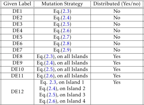
In this case, the total population is divided into islands, each island has its own individual evolution and also sends immigrants to neighboring islands as an exchange of information. In this thesis, five such variations are considered: 1) each island uses the mutation scheme described in equation (2.3);
Objectives
Steady State Error
Second Order System
Performance Comparison
Results and Analysis
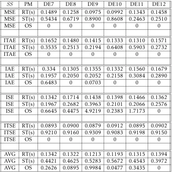
This shows that regardless of the mutation scheme, the DE variants can outperform conventional PID tuning methods. DE10 and DE12 are island-based and hybrid DE, respectively, and they can optimize 2/3 of the parameters better than their counterparts.
Convergence Speed Comparison
Results and Analysis
On average, non-distributed DE methods score 6.6 compared to 6.36 for distributed DE. One aspect that skews the best performing DE5 result is not being part of distributed mutation schemes.
Summary
The case study shows that GDE3 outperforms NSGA-II and other conventional tuning methods, and GDE3 yields an optimal Pareto front closer to the origin for this minimization problem. Aircraft pitch control is used as the case study to compare the performance of GDE3 and NSGA-II, and to demonstrate the advantages of multi-objective optimization.
System Model
Runtime analysis can be performed on the system in advance to ensure that it meets all standards. 4.1, it can be seen that this method can be applied to any system with an LQR controller.
Multiple Objectives
Both are conflicting goals [3]. Once the Pareto optimal solutions are obtained, they can be loaded into the decision system. The controller gains are obtained by an algorithm that can be dynamically changed based on the decision system.

Ensuring Stability and Controllability
To compute observability, the rank of [CT..CAn−1T] must be equal to the size of the matrix A, where the matrix C is state-to-output. All states in the state space models are controllable and observable, this is ensured by using minimal realization or pole-zero cancellation [66].
Optimization Parameters and Pre-compensation
Once the results are obtained, the pre-compensation process outlined in [66] is performed to adapt the output of the control system to the desired output. The scaling factor does not affect the targets using pre-compensation and a fair comparison between competing algorithms is ensured.
Complexity of Case Study
LQR Controller for Aircraft Pitch Control
Experimental Results
The decision maker can choose any solution from the Pareto optimal set, each solution is stable and optimized and obtained in a single optimization run.

Analysis
Summary
Chapters 3 and 4 serve as the foundation for the design optimization of the LQR-based ATS controller for car-trailer combination using GDE3. In designing the LQR-based ATS controllers, all vehicle and operating parameters were assumed to be constant.
Rearward Amplification (RWA)
In the design of the proposed ATS controller, the ATS controller at each control point is designed using LQR control technique. The effectiveness of the proposed ATS controller is demonstrated using numerical simulation based on a car trailer model.
Path-Following Off-Tracking
Design ATS Controller
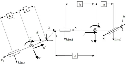
The yaw plane model takes into account the lateral and yaw movements of the car, as well as the yaw movement of the trailer. Where ψ is the articulation angle, r is the yaw rate of the car and r0 is the yaw rate of the trailer.
Single-lane Change Testing Maneuver
Distance between CG and rear axle b 1.7m Distance car CG to contact with trailer d 2.9m Distance trailer CG to contact with car e 3.8m Distance between the CG and the rear axle h 0.2m Height of vehicle CG H1CG 0.325m. The actuator is used to produce torque to drive the wheels on the trailer axle.
Testing Methodology
The fitness test performance measures for each solution are the RWA and the maximum lateral acceleration of the car. The algorithm minimizes the value of the car's peak lateral acceleration while trying to maintain an RWA of 1.0.
Results and Discussions
Critical Speed Analysis
Thus, the gain planning scheme can be implemented by considering the change in forward vehicle speed. In other words, the lateral acceleration of the trailer is 1.8 times greater than the lateral acceleration of the cars.
Forward Speed Variation
It can be found that the lateral acceleration of the trailer is amplified in the passive system compared to the car's lateral acceleration. From Fig. 5.9 to 5.16, it is observed that the LQR-based controller over-suppresses the lateral acceleration of the trailer under the SLC maneuver.

Summary
The supervisory performance of the optimized LQR controller is attributed to the application of the gain scheduling scheme and the optimization algorithm GDE3. Second, the linear 3-DOF model ignores some important dynamics of the real car-trailer combinations, for example the lateral load transformation.
CarSim Model and Methodology
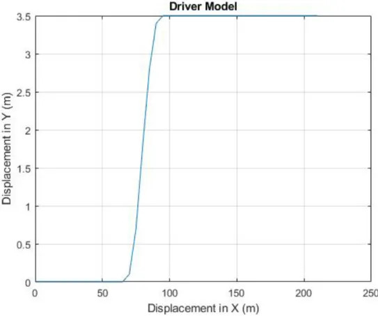
Built-in Driver Model Offered from CarSim
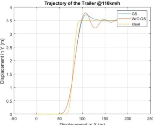
With a certain steering input, depending on the control gain, the trajectory of the truck-trailer changes. Two separate driver model parameters are used to generate the lookup table for GSC.
Evaluation Criteria
The centerpiece of this section is a lookup table for the gain scheduling controller (GSC) generated using GDE3.
Gain Scheduling Controller
Each gain is planned based on the vehicle's driving speed and the response time of the driver model. In other words, based on the vehicle's driving speed and the response time of the driver model, the controller gain is planned.
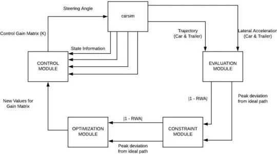
Modular Design Methodology
Whenever a control gain value K is chosen for the system, the vehicle's driving speed and the driver's reaction time will be the decisive parameters. The control module uses the parameters of the optimization module to generate control gain matrix K, which is then fed as steering angle from the ATS system to CarSim.
Overcoming System Limitation with Innovization
6.6, except for GDE3 Tuned, reach their optimal Pareto-front after the first step in establishing the SS and DV baseline. SS and DV are re-initialized based on the new information, and the constraints are changed from the design parameters to the range seen in the optimal Pareto front shown in Figure 2.
Algorithm Comparison
These results, together with the results from Chapter 5, prove that GDE3 is the better algorithm. Due to the expensive nature of testing and time constraints, the same test cannot be performed at other speeds.

Results: GDE3 Generated GSC vs Passive
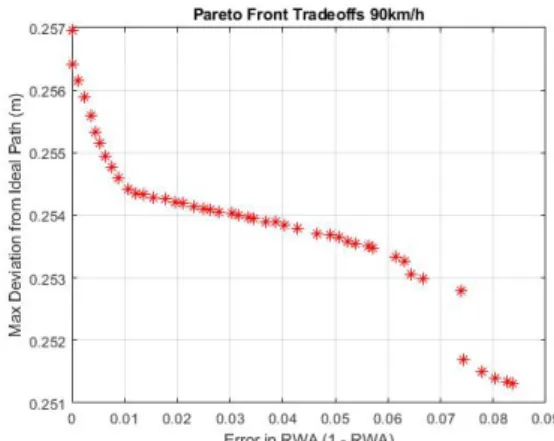
There are three main points of interest in every optimal Pareto front: the two utopia points (extreme points) and the optimal trade-off for the best compromise solution. From the progression of the optimal Pareto front for higher speeds and higher response times, the system constraint plays an integral role.
Results: Gain Scheduling
The simulation can be further fine-tuned to create a GSC that takes into account both the real driver and the vehicle's travel speed. First, the controller gains are changed as the speed increases beyond the next discrete step, e.g.
Important Observation
The GSC outperforms non-GSCs in improving the lateral stability and PFOT performance of car-trailer combinations. Building on the co-simulation, a multi-objective optimization method is applied to design the GSC.
Recommendations for Future Studies
A comparative study of active control strategies for improving lateral stability of car trailer systems. An optimal robust controller for active trailer differential braking systems of car-trailer combinations.
Point B is the knee-point. This image is taken from [51]
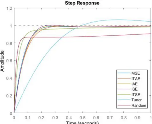
Responses for DE1 and MATLAB Tuner and Random Value
Responses for DE2 and MATLAB Tuner and Random Value
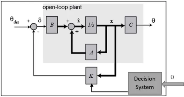
Feedback system model with LQR and decision support system
Feedback system model for aircraft pitch control with GDE3
Pareto-front obtained by GDE3 and NSGA-II on aircraft pitch
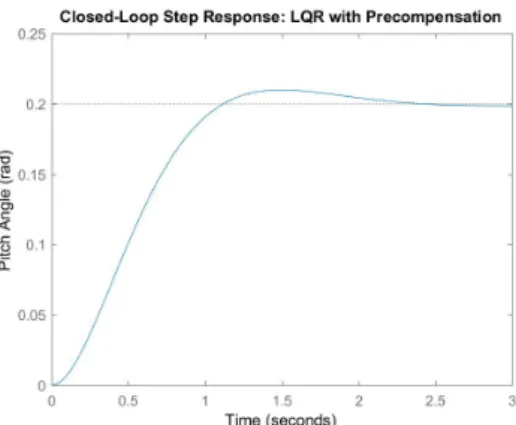
Response of the aircraft pitch control system with ST prioritized. 52
Response of the aircraft pitch control system obtained from [66]. 53
Lateral acceleration of the car at the critical speed 79.2km/h (with-
Optimal Pareto-front at 100km/h
Optimal Pareto-front at 110km/h
Lateral acceleration of the car at 80km /h
Lateral acceleration of the trailer at 100km /h
Lateral acceleration of the car at 110km /h
The experimental results for DE1 to DE6 and the average RT, ST
The experimental results for DE7 to DE12 and the average RT,
MATLAB PID tuner and random value results
Rank of DE Variants in Convergence Comparison
Control parameters of Optimization
Comparison Aircraft Pitch Control
Car-trailer combination parameters for ATS controller design
RWA Result Comparison
Peak Lateral Acceleration (g ) of Trailer Result Comparison
Vehicle parameter values
Possibilities of GSC Look-up Table