Application of Optical Reflex Sensors
TCRT1000, TCRT5000, CNY70
Vishay Semiconductor optoelectronic sensors contain infrared-emitting diodes as a radiation source and phototransistors as detectors.
Typical applications include:
Copying machines
Video recorders
Proximity switch
Vending machines
Printers
Object counters
Industrial control
Special features:
Compact design
Operation range 0 to 20 mm
High sensitivity
Low dark current
Minimized crosstalk
Ambient light protected
Cut-off frequency up to 40 kHz
High quality level, ISO 9000
Automated high-volume production
These sensors present the quality of perfected products. The components are based on Vishay Semiconductor’s many years’ experience as one of Europe’s largest producers of optoelectronic components.
Sensor Drawings
94 9318
TCRT1000
94 9442
TCRT5000
94 9320
Optoelectronic Sensors
In many applications, optoelectronic transmitters and receivers are used in pairs and linked together optically. Manufacturers fabricate them in suitable forms. They are available for a wide range of applications as ready-to-use components known as couplers, transmissive sensors (or interrupters), reflex couplers and reflex sensors. Increased automation in industry in particular has heightened the demand for these components and stimulated the development of new types.
General Principles
The operating principles of reflex sensors are similar to those of transmissive sensors. Basically, the light emitted by the transmitter is influenced by an object or a medium on its way to the detector. The change in the light signal caused by the interaction with the object then produces a change in the electrical signal in the optoelectronic receiver.
The main difference between reflex couplers and transmissive sensors is in the relative position of the transmitter and detector with respect to each other. In the case of the transmissive sensor, the receiver is opposite the transmitter in the same optical axis, giving a direct light coupling between the two. In the case of the reflex sensor, the detector is positioned next to the transmitter, avoiding a direct light coupling.
The transmissive sensor is used in most applications for small distances and narrow objects. The reflex sensor, however, is used for a wide range of distances as well as for materials and objects of different shapes.
In the following chapters, we will deal with reflex sensors placing particular emphasis on their practical use. The components TCRT1000, TCRT5000 and CNY70 are used as examples. However, references made to these components and their use apply to all sensors of a similar design.
The reflex sensors TCRT1000, TCRT5000 and CNY70 contain IR-emitting diodes as transmitters and phototransistors as receivers. The transmitters emit radiation of a wavelength of 950 nm. The spectral sensitivity of the phototransistors are optimized at this wavelength.
There are no focusing elements in the sensors described, though lenses are incorporated inside the TCRT5000 in both active parts (emitter and detector). The angular characteristics of both are divergent. This is necessary to realize a position-independent function for easy practical use with different reflecting objects.
In the case of TCRT5000, the concentration of the beam pattern to an angle of 16° for the emitter and 30° for the detector results in operation at an increased range with optimized resolution. The emitting and acceptance angles in the other reflex sensors are about 45°. This is an advantage in short distance operation.
The main difference between the sensor types is the mechanical outline (as shown in the figures, see previous page ), resulting in various electrical parameters and optical properties. A specialization for certain applications is necessary. Measurements and statements on the data of the reflex sensors are made relative to a reference surface with defined properties and precisely known reflecting properties. This reference medium is the diffusely reflecting Kodak neutral card, also known as gray card (KODAK neutral test card; KODAK publi-cation No. Q-13, CAT 1527654). It is also used here as the reference medium for all details. The reflection factor of the white side of the card is 90% and that of the gray side is 18%.
Table 1. Relative collector current (or coupling factor) of the reflex sensors for reflection on various materials. Reference is the white side of the Kodak neutral card. The sensor is positioned perpendicular to the surface. The wavelength is 950 nm.
Kodak neutral card
ÁÁÁÁÁÁÁÁÁÁÁÁÁ
ÁÁÁÁÁÁÁÁÁÁÁÁÁ
White side (reference medium) ÁÁÁ ÁÁÁ
100%
ÁÁÁÁÁÁÁÁÁÁÁÁÁ
ÁÁÁÁÁÁÁÁÁÁÁÁÁ
Gray side ÁÁÁ
ÁÁÁ
20%
Paper
ÁÁÁÁÁÁÁÁÁÁÁÁÁ
ÁÁÁÁÁÁÁÁÁÁÁÁÁ
Typewriting paper ÁÁÁ
ÁÁÁ
94%
ÁÁÁÁÁÁÁÁÁÁÁÁÁ
ÁÁÁÁÁÁÁÁÁÁÁÁÁ
Drawing card, white (Schoeller Durex) ÁÁÁ
ÁÁÁ
100%
ÁÁÁÁÁÁÁÁÁÁÁÁÁ
ÁÁÁÁÁÁÁÁÁÁÁÁÁ
Card, light gray ÁÁÁ
ÁÁÁ
67%
ÁÁÁÁÁÁÁÁÁÁÁÁÁ
ÁÁÁÁÁÁÁÁÁÁÁÁÁ
Envelope (beige) ÁÁÁ
ÁÁÁ
100%
ÁÁÁÁÁÁÁÁÁÁÁÁÁ
ÁÁÁÁÁÁÁÁÁÁÁÁÁ
Packing card (light brown) ÁÁÁ
ÁÁÁ
84%
ÁÁÁÁÁÁÁÁÁÁÁÁÁ
ÁÁÁÁÁÁÁÁÁÁÁÁÁ
Newspaper paper ÁÁÁ
ÁÁÁ 97% ÁÁÁÁÁÁÁÁÁÁÁÁÁ ÁÁÁÁÁÁÁÁÁÁÁÁÁ Pergament paper ÁÁÁ ÁÁÁ 30-42%
Black on white typewriting paper
ÁÁÁÁÁÁÁÁÁÁÁÁÁ
ÁÁÁÁÁÁÁÁÁÁÁÁÁ
Drawing ink (Higgins, Pelikan, Rotring)
ÁÁÁ
ÁÁÁ
4-6%
ÁÁÁÁÁÁÁÁÁÁÁÁÁ
ÁÁÁÁÁÁÁÁÁÁÁÁÁ
Foil ink (Rotring)
ÁÁÁ
ÁÁÁ
50%
ÁÁÁÁÁÁÁÁÁÁÁÁÁ
ÁÁÁÁÁÁÁÁÁÁÁÁÁ
Fiber-tip pen (Edding 400)
ÁÁÁ
ÁÁÁ
10%
ÁÁÁÁÁÁÁÁÁÁÁÁÁ
ÁÁÁÁÁÁÁÁÁÁÁÁÁ
Fiber-tip pen, black (Stabilo) ÁÁÁ
ÁÁÁ 76% ÁÁÁÁÁÁÁÁÁÁÁÁÁ ÁÁÁÁÁÁÁÁÁÁÁÁÁ Photocopy ÁÁÁ ÁÁÁ 7% Plotter pen ÁÁÁÁÁÁÁÁÁÁÁÁÁ ÁÁÁÁÁÁÁÁÁÁÁÁÁ
HP fiber–tip pen (0.3 mm) ÁÁÁ
ÁÁÁ
84%
ÁÁÁÁÁÁÁÁÁÁÁÁÁ
ÁÁÁÁÁÁÁÁÁÁÁÁÁ
ÁÁÁÁÁÁÁÁÁÁÁÁÁ
Black 24 needle printer (EPSON LQ-500) ÁÁÁ ÁÁÁ ÁÁÁ 28% ÁÁÁÁÁÁÁÁÁÁÁÁÁ ÁÁÁÁÁÁÁÁÁÁÁÁÁ Ink (Pelikan) ÁÁÁ ÁÁÁ 100% ÁÁÁÁÁÁÁÁÁÁÁÁÁ Pencil, HB ÁÁÁ 26% Plastics, glass ÁÁÁÁÁÁÁÁÁÁÁÁÁ ÁÁÁÁÁÁÁÁÁÁÁÁÁ
White PVC ÁÁÁ
ÁÁÁ
90%
ÁÁÁÁÁÁÁÁÁÁÁÁÁ
ÁÁÁÁÁÁÁÁÁÁÁÁÁ
Gray PVC ÁÁÁ
ÁÁÁ
11%
ÁÁÁÁÁÁÁÁÁÁÁÁÁ
ÁÁÁÁÁÁÁÁÁÁÁÁÁ
Blue, green, yellow, red PVC ÁÁÁ
ÁÁÁ
40-80%
ÁÁÁÁÁÁÁÁÁÁÁÁÁ
ÁÁÁÁÁÁÁÁÁÁÁÁÁ
White polyethylene ÁÁÁ
ÁÁÁ
90%
ÁÁÁÁÁÁÁÁÁÁÁÁÁ
ÁÁÁÁÁÁÁÁÁÁÁÁÁ
White polystyrene ÁÁÁ
ÁÁÁ
120%
ÁÁÁÁÁÁÁÁÁÁÁÁÁ
ÁÁÁÁÁÁÁÁÁÁÁÁÁ
Gray partinax ÁÁÁ
ÁÁÁ
9%
Fiber glass board material
ÁÁÁÁÁÁÁÁÁÁÁÁÁ
ÁÁÁÁÁÁÁÁÁÁÁÁÁ
Without copper coating ÁÁÁ
ÁÁÁ
12-19%
ÁÁÁÁÁÁÁÁÁÁÁÁÁ
ÁÁÁÁÁÁÁÁÁÁÁÁÁ
With copper coating on the reverse side ÁÁÁ ÁÁÁ 30% ÁÁÁÁÁÁÁÁÁÁÁÁÁ ÁÁÁÁÁÁÁÁÁÁÁÁÁ
Glass, 1 mm thick
ÁÁÁ
ÁÁÁ
9%
ÁÁÁÁÁÁÁÁÁÁÁÁÁ
ÁÁÁÁÁÁÁÁÁÁÁÁÁ
Plexiglass, 1 mm thick ÁÁÁ
ÁÁÁ
10%
Metals
ÁÁÁÁÁÁÁÁÁÁÁÁÁ
ÁÁÁÁÁÁÁÁÁÁÁÁÁ
Aluminum, bright ÁÁÁ
ÁÁÁ
110%
ÁÁÁÁÁÁÁÁÁÁÁÁÁ
ÁÁÁÁÁÁÁÁÁÁÁÁÁ
Aluminum, black anodized ÁÁÁ
ÁÁÁ
60%
ÁÁÁÁÁÁÁÁÁÁÁÁÁ
ÁÁÁÁÁÁÁÁÁÁÁÁÁ
Cast aluminum, matt ÁÁÁ
ÁÁÁ
45%
ÁÁÁÁÁÁÁÁÁÁÁÁÁ
ÁÁÁÁÁÁÁÁÁÁÁÁÁ
Copper, matt (not oxidized) ÁÁÁ
ÁÁÁ
110%
ÁÁÁÁÁÁÁÁÁÁÁÁÁ
ÁÁÁÁÁÁÁÁÁÁÁÁÁ
Brass, bright ÁÁÁ
ÁÁÁ
160%
ÁÁÁÁÁÁÁÁÁÁÁÁÁ
ÁÁÁÁÁÁÁÁÁÁÁÁÁ
Gold plating, matt ÁÁÁ
ÁÁÁ 150% Textiles ÁÁÁÁÁÁÁÁÁÁÁÁÁ ÁÁÁÁÁÁÁÁÁÁÁÁÁ White cotton ÁÁÁ ÁÁÁ 110% ÁÁÁÁÁÁÁÁÁÁÁÁÁ Black velvet ÁÁÁ 1.5%
Parameters and Practical Use of the Reflex Sensors
A reflex sensor is used in order to receive a reflected signal from an object. This signal gives information on the position, movement, size or condition (e.g. coding) of the object in question. The parameter that describes the function of the optical coupling precisely is the so-called optical transfer function (OT) of the sensor. It is the ratio of the received to the emitted radiant power.
OTr
e
Additional parameters of the sensor, such as operating range, the resolution of optical distance of the object, the sensitivity and the switching point in the case of lo-cal changes in the reflection, are directly related to this optical transfer function.
In the case of reflex sensors with phototransistors as receivers, the ratio Ic/IF (the ratio of collector current Ic
to the forward current IF) of the diode emitter is
pre-ferred to the optical transfer function. As with optocouplers, Ic/IF is generally known as the coupling
factor, k. The following approximate relationship exists between k and OT:
k = Ic/ IF = [(S B)/h] r/e
where B is the current amplification, S = Ib/Φr (phototransistor’s spectral sensitivity), and h = IF/Φe
(proportionality factor between IF and Φe of the
In figures7 and 8, the curves of the radiant intensity, Ie,
of the transmitter to the forward current, IF, and the
sensitivity of the detector to the irradiance, Ee, are
shown respectively. The gradients of both are equal to unity slope.
This represents a measure of the deviation of the curves from the ideal linearity of the parameters. There is a good proportionality between Ie and IF and
between Ic and Ee where the curves are parallel to the
unity gradient.
Greater proportionality improves the relationship between the coupling factor, k, and the optical transfer function.
Figure 7. Radiant intensity, Ie = f (IF), of the IR transmitter
Coupling Factor, k
In the case of reflex couplers, the specification of the coupling factor is only useful by a defined reflection and distance. Its value is given as a percentage and refers here to the diffuse reflection (90%) of the white side of Kodak neutral card at the distance of the maximum light coupling. Apart from the transmitter current, IF, and the temperature, the coupling factor
also depends on the distance from the reflecting
surface and the frequency that is, the speed of reflection change.
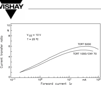
For all reflex sensors, the curve of the coupling factor as a function of the transmitter current, IF, has a flat maximum at approximately 30 mA (figure 9). As shown in the figure, the curve of the coupling factor follows that of the current amplification, B, of the phototransistor. The influence of temperature on the coupling factor is relatively small and changes approximately –10% in the range of –10 to +70°C (figure 10). This fairly favorable temperature compensation is attributable to the opposing temperature coefficient of the IR diode and the phototransistor.
The maximum speed of a reflection change that is detectable by the sensor as a signal is dependent either on the switching times or the threshold frequency, fc, of the component. The threshold
frequency and the switching times of the reflex sensors TCRT1000, TCRT5000, and CNY70 are determined by the slowest component in the system in this case the phototransistor. As usual, the threshold frequency, fc, is defined as the frequency at which the
value of the coupling factor has fallen by 3 dB (approximately 30%) of its initial value. As the frequency increases, f > fc, the coupling factor
decreases.
Figure 9. Coupling factor k = f (IF) of the reflex sensors
Figure 10. Change of the coupling factor, k, with temperature, T
As a consequence, the reflection change is no longer easily identified.
Figure 11 illustrates the change of the cut-off frequency at collector emitter voltages of 5, 10 and 20 V and various load resistances. Higher voltages and low load resistances significantly increase the cut-off frequency.
The cut-off frequencies of all Vishay Semiconductor reflex sensors are high enough (with 30 to 50 kHz) to recognize extremely fast mechanical events.
In practice, it is not recommended to use a large load resistance to obtain a large signal, dependent on the speed of the reflection change. Instead, the opposite effect takes place, since the signal amplitude is markedly reduced by the decrease in the cut-off frequency. In practice, the better approach is to use the given data of the application (such as the type of mechanical movement or the number of markings on the reflective medium). With these given data, the maximum speed at which the reflection changes can be determined, thus allowing the maximum frequency occurring to be calculated. The maximum permissible load resistance can then be selected for this frequency
from the diagram fc as a function of the load
resistance, RL.
Working Diagram
The dependence of the phototransistor collector current on the distance, A, of the reflecting medium is shown in figures 12 and 13 for the reflex sensor TCRT1000.
The data were recorded for the Kodak neutral card with 90% diffuse reflection serving as the reflecting surface, arranged perpendicular to the sensor. The distance, A, was measured from the surface of the reflex sensor.
The emitter current, IF, was held constant during the
measurement. Therefore, this curve also shows the course of the coupling factor and the optical transfer function over distance. It is called the working diagram of the reflex sensor.
The working diagrams of all sensors (figure 12) shows a maximum at a certain distance, Ao. Here the optical
coupling is the strongest. For larger distances, the collector current falls in accordance with the square law. When the amplitude, I, has fallen not more than 50% of its maximum value, the operation range is at its optimum.
a) TCRT5000
b) CNY 70
c) TCRT1000
Figure 12. Working diagram of reflex sensors TCRT5000, CNY70 and TCRT1000
Resolution, Trip Point
The behavior of the sensors with respect to abrupt changes in the reflection over a displacement path is determined by two parameters: the resolution and the trip point.
If a reflex sensor is guided over a reflecting surface with a reflection surge, the radiation reflected back to the detector changes gradually, not abruptly. This is depicted in figure 13a. The surface, g, seen jointly by the transmitter and detector, determines the radiation received by the sensor. During the movement, this surface is gradually covered by the dark reflection range. In accordance with the curve of the radiation detected, the change in collector current is not abrupt, but undergoes a wide, gradual transition from the higher to the lower value.
As illustrated in figure 13b, the collector current falls to the value Ic2, which corresponds to the reflection of the
dark range, not at the point Xo, but at the points
Xo + Xd/2, displaced by Xd/2.
The displacement of the signal corresponds to an uncertainty when recording the position of the reflection change, and it determines the resolution and the trip point of the sensor.
The trip point is the position at which the sensor has completely recorded the light/ dark transition, that is, the range between the points Xo + Xd/2 and Xo – Xd/2
around Xo. The displacement, Xd, therefore,
corresponds to the width or the tolerance of the trip point. In practice, the section lying between 10 and 90% of the difference Ic = Ic1 – Ic2 is taken as Xd. This corresponds to the rise time of the generated signal since there is both movement and speed. Analogous to switching time, displacement, Xd, is described as a
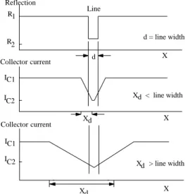
The resolution is the sensor’s capability to recognize small structures. Figure 13 illustrates the example of the curve of the reflection and current signal for a black line measuring d in width on a light background (e.g. on a sheet of paper). The line has two light/ dark transi-tions the switching distance Xd/2 is, therefore, effective twice.
g a)
b)
Figure 13. Abrupt reflection change with associated Ic curve
The line is clearly recognized as long as the line width is d Xd. If the width is less than Xd, the collector
current change, Ic1 – Ic2, that is the processable signal,
becomes increasingly small and recognition increas-ingly uncertain. The switching distance or better its inverse can therefore be taken as a resolution of the sensor.
The switching distance, Xd, is predominantly
depen-dent on the mechanical/ optical design of the sensor and the distance to the reflecting surface. It is also in-fluenced by the relative position of the transmitter/ detector axis.
X < line widthd
X > line widthd Collector current
IC1
IC1 IC2
IC2
Collector current
Xd Xd
d X
X
X R1
R2 Reflection
Line
d = line width
Figure 14. Reflection of a line of width d and corresponding curve of the collector current Ic
Figure 14 shows the dependence of the switching distance, Xd, on the distance A with the sensors placed in two different positions with respect to the separation line of the light/ dark transition.
The curves marked position 1 in the diagrams correspond to the first position. The transmitter/ detector axis of the sensor was perpendicular to the separation line of the transition. In the second position (curve 2), the transmitter/ detector axis was parallel to the transition.
In the first position (1) all reflex sensors have a better resolution (smaller switching distances) than in position 2. It can recognize lines smaller than half a millimeter at a distance below 0.5 mm.
It should be remarked that the diagram of TCRT5000 is scaled up to 10 cm. It shows best resolution between 2 and 10 cm.
All sensors show the peculiarity that the maximum resolution is not at the point of maximum light coupling, Ao, but at shorter distances.
Since the radiation received by the sensor’s detector depends greatly on the distance, the case may arise when the difference between the radiation reflected by the object on the background is completely equalized by the distance despite varying reflectance factors. Even if the sensor has sufficient resolution, it will no
longer supply a processable signal due to the low re-flection difference. In such applications it is necessary to examine whether there is a sufficient contrast. This is performed with the help of the working diagram of the sensor and the reflectance factors of the materials.
a) TCRT5000
b) CNY70
c) TCRT1000
Sensitivity, Dark Current and Crosstalk
The lowest photoelectric current that can be processed as a useful signal in the sensor’s detector determines the weakest usable reflection and defines the sensitivity of the reflex sensor. This is determined by two parameters – the dark current of the phototransistor and the crosstalk.
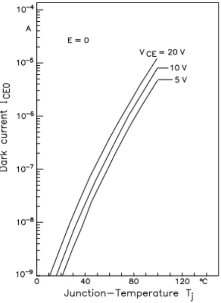
The phototransistor as receiver exhibits a small dark current, ICEO, of a few nA at 25°C. However, it is
dependent on the applied collector-emitter voltage, VCE, and to a much greater extent on the temperature,
T (see figure 16). The crosstalk between the transmitter and detector of the reflex sensor is given with the current, Icx. Icx is the collector current of the
photoelectric transistor measured at normal IR transmitter operating conditions without a reflecting medium.
Figure 16. Temperature-dependence of the collector dark current
It is ensured that no (ambient) light falls onto the photoelectric transistor. This determines how far it is possible to guarantee avoiding a direct optical connection between the transmitter and detector of the sensor.
At IF = 20 mA, the current Icx is approximately 15 nA
for the CNY70, TCRT1000 and TCRT5000.
Icx can also be manifested dynamically. In this case,
the origin of the crosstalk is electrical rather than optical.
For design and optical reasons, the transmitter and detector are mounted very close to each other.
Electrical interference signals can be generated in the detector when the transmitter is operated with a pulsed or modulated signal. The transfer capability of the interference increases strongly with the frequency. Steep pulse edges in the transmitter’s current are particularly effective here since they possess a large portion of high frequencies. For all Vishay Semicon-ductor sensors, the ac crosstalk, Icxac, does not
become effective until frequencies of 4 MHz upwards with a transmission of approximately 3 dB between the transmitter and detector.
The dark current and the dc - and ac crosstalk form the overall collector fault current, Icf. It must be observed
that the dc-crosstalk current, Icxdc, also contains the
dark current, ICEO, of the phototransistor.
Icf = Icxdc + Icxac
This current determines the sensitivity of the reflex sensor. The collector current caused by a reflection change should always be at least twice as high as the fault current so that a processable signal can be reli-ably identified by the sensor.
Ambient Light
Ambient light is another feature that can impair the sensitivity and, in some circumstances, the entire function of the reflex sensor. However, this is not an artifact of the component, but an application specific characteristic.
The effect of ambient light falling directly on the detector is always very troublesome. Weak steady light reduces the sensor’s sensitivity. Strong steady light can, depending on the dimensioning (RL, VC),
saturate the photoelectric transistor. The sensor is ‘blind’ in this condition. It can no longer recognize any reflection change. Chopped ambient light gives rise to incorrect signals and feigns non-existent reflection changes.
If the ambient light has wavelengths for which the ratio of the reflection factors of the object and background is the same or similar, its influence on the sensor’s function is small. Its effect can be ignored for intensities that are not excessively large. On the other hand, the object/ background reflection factors can differ from each other in such a way that, for example, the background reflects the ambient light much more than the object. In this case, the contrast disappears and the object cannot be detected. It is also possible that an uninteresting object or feature is detected by the sensor because it reflects the ambient light much more than its surroundings.
In practice, ambient light stems most frequently from filament, fluorescent or energysaving lamps. Table 2 gives a few approximate values of the irradiance of these sources. The values apply to a distance of approximately 50 cm, the spectral range to a distance of 850 to 1050 nm. The values of table 2 are only intended as guidelines for estimating the expected ambient radiation.
In practical applications, it is generally rather difficult to
determine the ambient light and its effects precisely. Therefore, an attempt to keep its influence to a minimum is made from the outset by using a suitable mechanical design and optical filters. The detectors of the sensors are equipped with optical filters to block such visible light. Furthermore, the mechanical design of these components is such that it is not possible for ambient light to fall directly or sideways onto the detector for object distances of up to 2 mm.
If the ambient light source is known and is relatively weak, in most cases it is enough to estimate the expected power of this light on the irradiated area and to consider the result when dimensioning the circuit.
AC operation of the reflex sensors offers the most effective protection against ambient light. Pulsed operation is also helpful in some cases.
Compared with dc operation, the advantages are greater transmitter power and at the same time significantly greater protection against faults. The only disadvantage is the greater circuit complexity, which is necessary in this case. The circuit in figure 20 is an example of operation with chopped light.
Table 2. Examples for the irradiance of ambient light sources
Light source (at 50 cm distance) Irradiance Ee (µW/cm2)
850 to 1050 nm
Frequency (Hz)
Steady light AC light (peak value)
ÁÁÁÁÁÁÁÁÁÁÁÁÁÁÁ
ÁÁÁÁÁÁÁÁÁÁÁÁÁÁÁ
Filament lamp (60 W)
ÁÁÁÁÁ
ÁÁÁÁÁ
500
ÁÁÁÁÁÁÁÁÁ
ÁÁÁÁÁÁÁÁÁ
ÁÁÁÁÁÁ
ÁÁÁÁÁÁ ÁÁÁÁÁÁÁÁÁÁÁÁÁÁÁ
ÁÁÁÁÁÁÁÁÁÁÁÁÁÁÁ
Fluorescent lamp OSRAM (65 W)
ÁÁÁÁÁ
ÁÁÁÁÁ
25
ÁÁÁÁÁÁÁÁÁ
ÁÁÁÁÁÁÁÁÁ
30
ÁÁÁÁÁÁ
ÁÁÁÁÁÁ
100
ÁÁÁÁÁÁÁÁÁÁÁÁÁÁÁ
ÁÁÁÁÁÁÁÁÁÁÁÁÁÁÁ
Economy lamp OSRAM DULUX (11 W)
ÁÁÁÁÁ
ÁÁÁÁÁ
14
ÁÁÁÁÁÁÁÁÁ
ÁÁÁÁÁÁÁÁÁ
16
ÁÁÁÁÁÁ
ÁÁÁÁÁÁ
Application Examples, Circuits
The most important characteristics of the Vishay Semiconductor reflex sensors are summarized in table 3. The task of this table is to give a quick comparison of data for choosing the right sensor for a given application.Application Example with Dimensioning
With a simple application example, the dimensioning of the reflex sensor can be shown in the basic circuit with the aid of the component data and considering the boundary conditions of the application.
The reflex sensor is used for speed control. An aluminum disk with radial strips as markings fitted to the motor shaft forms the reflecting object and is located approximately 3 mm in front of the sensor. The sensor signal is sent to a logic gate for further processing.
Dimensioning is based on dc operation, due to the simplified circuitry.
The optimum transmitter current. IF, for dc operation is
between 20 and 40 mA. IF = 20 mA is selected in this
case.
As shown in figure 17, the coupling factor is at its maximum. In addition, the degradation (i.e. the reduction of the transmitted IR output with aging) is minimum for currents under 40 mA (< 10% for 10000 h) and the self heating is low due to the power loss (approximately 50 mW at 40 mA).
RS RE
15 k 180 TCRT5000 74HCTXX GND +5 V Q
Figure 17. Reflex sensor - basic circuit
Table 3.
Parameter Symbol Reflex Sensor Type
ÁÁÁÁÁÁÁÁÁÁÁÁ ÁÁÁÁÁÁÁÁÁÁÁÁ ÁÁÁÁÁ ÁÁÁÁÁ ÁÁÁÁÁÁÁ ÁÁÁÁÁÁÁ CNY70 ÁÁÁÁÁÁÁ ÁÁÁÁÁÁÁ TCRT1000 ÁÁÁÁÁÁÁ ÁÁÁÁÁÁÁ TCRT5000 ÁÁÁÁÁÁÁÁÁÁÁÁ ÁÁÁÁÁÁÁÁÁÁÁÁ
Distance of optimum coupling ÁÁÁÁÁ
ÁÁÁÁÁ
A0
ÁÁÁÁÁÁÁ
ÁÁÁÁÁÁÁ
0.3 mm ÁÁÁÁÁÁÁ
ÁÁÁÁÁÁÁ
1 mm ÁÁÁÁÁÁÁ
ÁÁÁÁÁÁÁ
2 mm
ÁÁÁÁÁÁÁÁÁÁÁÁ
ÁÁÁÁÁÁÁÁÁÁÁÁ
Distance of best resolution ÁÁÁÁÁ
ÁÁÁÁÁ
Ar
ÁÁÁÁÁÁÁ
ÁÁÁÁÁÁÁ
0.2 mm ÁÁÁÁÁÁÁ
ÁÁÁÁÁÁÁ
0.8 mm ÁÁÁÁÁÁÁ
ÁÁÁÁÁÁÁ
1.5 mm
ÁÁÁÁÁÁÁÁÁÁÁÁ
ÁÁÁÁÁÁÁÁÁÁÁÁ
Coupling factor ÁÁÁÁÁ
ÁÁÁÁÁ k ÁÁÁÁÁÁÁ ÁÁÁÁÁÁÁ 5% ÁÁÁÁÁÁÁ ÁÁÁÁÁÁÁ 5% ÁÁÁÁÁÁÁ ÁÁÁÁÁÁÁ 6% ÁÁÁÁÁÁÁÁÁÁÁÁ ÁÁÁÁÁÁÁÁÁÁÁÁ
Switching distance (min.) ÁÁÁÁÁ
ÁÁÁÁÁ
xd ÁÁÁÁÁÁÁ
ÁÁÁÁÁÁÁ
1.5 mm ÁÁÁÁÁÁÁ
ÁÁÁÁÁÁÁ
0.7 mm ÁÁÁÁÁÁÁ
ÁÁÁÁÁÁÁ
1.9 mm
ÁÁÁÁÁÁÁÁÁÁÁÁ
ÁÁÁÁÁÁÁÁÁÁÁÁ
Optimum working distance ÁÁÁÁÁ
ÁÁÁÁÁ
XorÁÁÁÁÁÁÁ
ÁÁÁÁÁÁÁ
0.2 to 3 mm ÁÁÁÁÁÁÁ
ÁÁÁÁÁÁÁ
0.4 to 2.2 mm ÁÁÁÁÁÁÁ
ÁÁÁÁÁÁÁ
0.2 to 6.5 mm
ÁÁÁÁÁÁÁÁÁÁÁÁ
ÁÁÁÁÁÁÁÁÁÁÁÁ
Operating range ÁÁÁÁÁ
ÁÁÁÁÁ
AorÁÁÁÁÁÁÁ
ÁÁÁÁÁÁÁ
9 mm ÁÁÁÁÁÁÁ
ÁÁÁÁÁÁÁ
8 mm ÁÁÁÁÁÁÁ
ÁÁÁÁÁÁÁ
> 20 mm
Table 4. Application Data ÁÁÁÁÁÁÁ ÁÁÁÁÁÁÁ Aluminum disk ÁÁÁÁÁÁÁÁÁÁÁÁÁÁÁÁÁÁÁÁÁÁÁÁÁÁ ÁÁÁÁÁÁÁÁÁÁÁÁÁÁÁÁÁÁÁÁÁÁÁÁÁÁ
Diameter 50 mm, distance from the sensor 3 mm, markings printed on the aluminum
ÁÁÁÁÁÁÁ ÁÁÁÁÁÁÁ ÁÁÁÁÁÁÁ Markings ÁÁÁÁÁÁÁÁÁÁÁÁÁÁÁÁÁÁÁÁÁÁÁÁÁÁ ÁÁÁÁÁÁÁÁÁÁÁÁÁÁÁÁÁÁÁÁÁÁÁÁÁÁ ÁÁÁÁÁÁÁÁÁÁÁÁÁÁÁÁÁÁÁÁÁÁÁÁÁÁ
8 radial black stripes and 8 spacings, the width of the stripes and spacings in front of the sensor is approximately = 4 mm (in a diameter of 20 mm)
ÁÁÁÁÁÁÁ
ÁÁÁÁÁÁÁ
Motor speed ÁÁÁÁÁÁÁÁÁÁÁÁÁÁÁÁÁÁÁÁÁÁÁÁÁÁ
ÁÁÁÁÁÁÁÁÁÁÁÁÁÁÁÁÁÁÁÁÁÁÁÁÁÁ
1000 to 3000 rpm
ÁÁÁÁÁÁÁ
Temperature range
ÁÁÁÁÁÁÁÁÁÁÁÁÁÁÁÁÁÁÁÁÁÁÁÁÁÁ
10 to 60°C
ÁÁÁÁÁÁÁ
ÁÁÁÁÁÁÁ
Ambient light
ÁÁÁÁÁÁÁÁÁÁÁÁÁÁÁÁÁÁÁÁÁÁÁÁÁÁ
ÁÁÁÁÁÁÁÁÁÁÁÁÁÁÁÁÁÁÁÁÁÁÁÁÁÁ
60 W fluorescent lamp, approximate distance 2 m
ÁÁÁÁÁÁÁ
ÁÁÁÁÁÁÁ
Power supply
ÁÁÁÁÁÁÁÁÁÁÁÁÁÁÁÁÁÁÁÁÁÁÁÁÁÁ
ÁÁÁÁÁÁÁÁÁÁÁÁÁÁÁÁÁÁÁÁÁÁÁÁÁÁ
5 V ± 5%
ÁÁÁÁÁÁÁ
ÁÁÁÁÁÁÁ
ÁÁÁÁÁÁÁ
Position of the sensor
ÁÁÁÁÁÁÁÁÁÁÁÁÁÁÁÁÁÁÁÁÁÁÁÁÁÁ
ÁÁÁÁÁÁÁÁÁÁÁÁÁÁÁÁÁÁÁÁÁÁÁÁÁÁ
ÁÁÁÁÁÁÁÁÁÁÁÁÁÁÁÁÁÁÁÁÁÁÁÁÁÁ
Special attention must also be made to the downstream logic gate. Only components with a low input offset current may be used. In the case of the TTL gate and the LS-TTL gate, the ILH current can be
applied to the sensor output in the low condition. At –1.6 mA or –400 µA, this is above the signal current of the sensor. A transistor or an operational amplifier should be connected at the output of the sensor when TTL or LS-TTL components are used. A gate from the 74HCTxx family is used.
According to the data sheet, its fault current ILH is
approximately 1 µA.
The expected collector current for the minimum and maximum reflection is now estimated.
According to the working diagram in figure 12a, it follows that when A = 3 mm
Ic = 0.95 Icmax
Icmax is determined from the coupling factor, k,
for IF = 10 mA.
Icmax = k IF
At IF = 10 mA, the typical value
k = 2.8%
is obtained for k from figure 9.
However, this value applies to the Kodak neutral card or the reference surface. The coupling factor has a different value for the surfaces used (typewriting paper and black-fiber tip pen). The valid value for these material surfaces can be found in table 1:
k1 = 94% k = 4.7% for typing paper and
k2 = 10% k = 0.5% for black-tip pen (Edding)
Therefore: Ic1 = 0.95 k1 IF = 446.5 µA
Ic2 = 0.95 k2 IF = 47.5 µA
Temperature and aging reduce the collector current. They are therefore important to Ic1 and are subtracted
from it.
Figure 10 shows a change in the collector current of approximately 10% for 70°C. Another 10% is deducted from Ic1 for aging
Ic1 = 263 µA – (20% 263 µA) = 357.2 µA
The fault current Icf (from crosstalk and collector dark
current) increases the signal current and is added to
Ic2. Crosstalk with only a few nA for the TCRT5000 is
ignored. However, the dark current can increase up to 1 µA at a temperature of 70°C and should be taken into account.
In addition, 1 µA, the fault current of the 74HCTxx gate, is also added
Ic2 = 49.5 µA
The effect of the indirect incident ambient light can most easily be seen by comparing the radiant powers produced by the ambient light and the sensor’s transmitter on 1 mm2 of the reflecting surface. The ambient light is then taken into account as a percentage in accordance with the ratio of the powers.
From table 2:
Ee (0.5 m) = 40 µW/ cm2 (dc + ac/ 2)
Ee (2 m) = Ee(0.5 m) (0.5/ 2)2
(Square of the distance law)
Ee (2 m) = 2.5 µW/ cm2
sf = 0.025 W
The radiant power (Φsf = 0.025 µW)
therefore falls on 1 mm2.
When IF = 10 mA, the sensor’s transmitter has the
radiant intensity:
Ie e
0.25 Wsr
(see figure 7)
The solid angle for 1 mm2 surface at a distance of 3 mm is
(3 mm)1 mm22 1 9sr
It therefore follows for the radiant power that:
e = Ie = ca. 27.8 mW
The power of 0.025 µW produced by the ambient light is therefore negligibly low compared with the corresponding power (approximately 28 µW) of the transmitter.
The currents Ic1, Ic2 would result in full reflecting
The signal can be markedly reduced by the limited resolution of the sensor if the stripes are narrow. The suitable stripe width for a given distance should therefore be selected from figure 15. In this case, the minimum permissible stripe width is approximately 2.5 mm for a distance of 3 mm (position 1, figure 15a). The markings measuring 4 mm in width were expediently selected in this case. For this width, a signal reduction of about 20% can be permitted with relatively great certainty, so that 10% of the difference (Ic1 – Ic2) can be subtracted from Ic1 and added to Ic2.
Ic1 = 357.2 A – 30.8 A = 326.4 A
Ic2 = 49.5 A + 30.8 A = 80.3 A
The suitable load resistance, RE, at the emitter of the
photo-transistor is then determined from the low and high levels 0.8 V and 2.0 V for the 74HCTxx gate.
RE < 0.8 V/ Ic2 and RE > 2.0 V/ Ic1, i.e., 6.1 k < RE < 9.96 k
6.8 k is selected for RE
The corresponding levels for determining RE must be
used if a Schmitt trigger of the 74HCTxx family is employed.
The frequency limit of the reflex sensor is then determined with RE = 6.8 k and compared with the
maximum operating frequency in order to check whether signal damping attributable to the frequency can occur.
Figure 11 shows for Vs = 5 V and RE = 6.8 k
approximately, for the TCRT5000, fc = 3.0 kHz.
Sixteen black/ white stripes appear in front of the sensor in each revolution. This produces a maximum signal frequency of approximately 400 Hz for the maximum speed of 3000 rpm up to 50 rps. This is significantly less than the fc of the sensor, which
means there is no risk of signal damping.
In the circuit in figure 17, a resistor, Rc, can be used on
the collector of the photoelectric transistor instead of RE. In this case, an inverted signal and somewhat
modified dimensioning results. The current Ic1 now
determines the low signal level and the current Ic2 the
high. The voltages (Vs – 2 V) and (Vs – 0.8 V) and not the high level and low level 2 V and 0.8 V, are now decisive for determining the resistance, Rc.
Circuits with Reflex Sensors
The couple factor of the reflex sensors is relatively small. Even in the case of good reflecting surfaces, it is less than 10%. Therefore, the photocurrents are in practice only in the region of a few µA. As this is not enough to process the signals any further, an additional amplifier is necessary at the sensor output.
Figure 18 shows two simple circuits with sensors and follow-up operational amplifiers.
The circuit in figure 18b is a transimpedance which offers in addition to the amplification the advantage of a higher cut-off frequency for the whole layout.
Two similar amplification circuits incorporating transistors are shown in figure 19.
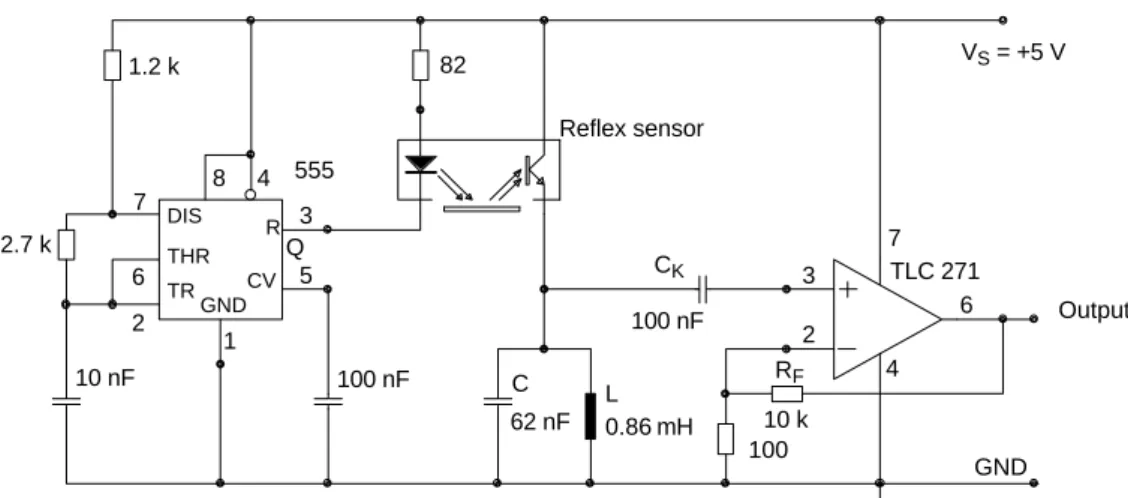
The circuit in figure 20 is a simple example for operating the reflex sensors with chopped light. It uses a pulse generator constructed with a timer IC. This pulse generator operates with the pulse duty factor of approximately 1. The frequency is set to approximately 22 kHz. On the receiver side, a conventional LC resonance circuit (fo = 22 kHz) filters the fundamental wave out of the received pulses and delievers it to an operational amplifier via the capacitor, Ck. The LC resonance circuit simultaneously
represents the photo transistor’s load resistance. For direct current, the photo transistor’s load resistance is very low in this case approximately 0.4, which means that the photo transistor is practically shorted for dc ambient light.
At resonance frequencies below 5 kHz, the necessary coils and capacitors for the oscillator become unwieldy and expensive. Therefore, active filters, made up with operational amplifiers or transistors, are more suitable (figures 21 and 22). It is not possible to obtain the quality characteristics of passive filters. In addition the load resistance on the emitter of the photo transistor has remarkably higher values than the dc resistance of a coil. On the other hand, the construction with active filters is more compact and cheaper. The smaller the resonance frequency becomes, the greater the advantages of active filters compared to LC resonant circuits.
It should be mentioned that such a circuit is only suited to evenly distributed objects and constant movements. If this is not the case, the channels must be close to each other, so that the movement of both sensors are collected successively. The circuit also works perfectly if the last mentioned condition is fulfilled. Figure 24 shows a pulse circuit combining analog with digital components and offering the possibility of temporary storage of the signal delivered by the reflex sensor. A timer IC is used as the pulse generator.
The negative pulse at the timer’s output triggers the clock input of the 74HCT74 flip-flop and, at the same
time, the reflex sensor’s transmitter via a driver transistor. The flip-flop can be positively triggered, so that the condition of the data input at this point can be received as the edge of the pulse rises. This then remains stored until the next rising edge.
The reflex sensor is therefore only active for the duration of the negative pulse and can only detect reflection changes within this time period. During the time of negative impulses, electrical and optical interferences are suppressed. A sample and hold circuit can also be employed instead of the flip-flop. This is switched on via an analog switch at the sensor output as the pulse rises.
+10 V b)
+10 V
Reflex sensor
7 2
3
6 TLC271
Reflex sensor
7
4 2
3
6 TLC271
6
4
GND GND
Output Output
a)
IF = 20 mA
RS RE R F
RI
390 1 k
1 k 220 k
IF = 20 mA RF
220 k
RS
390
RE
1 k RI
1 k
Figure 18. Circuits with operational amplifier
+10 V b)
+10 V a)
BC178B PNP
Reflex sensor
Reflex sensor
GND GND
Output
Output
IF = 20 mA
RS
390
RC
1 k
RE
220
RL
10 k
IF = 20 mA
RS
390
RE
1 k 2.2 F CK
RF
220 k
RL 1 k
BC108B PNP
Reflex sensor
Q 3
2 1 6 5 7
4 8 555
100 nF
TLC 271
4 3
2
6 7
100 62 nF
C 100 nF
10 nF
GND
Output 1.2 k
2.7 k
TR DIS
THR
GND CV
82
L 0.86 mH
RF
10 k CK
R
VS = +5 V
Figure 20. AC operation with oscillating circuit to suppress ambient light
1 nF
4 2
3
6 7 R R Reflex sensor
3
2
1 6
5 7
4 8 Timer
C
100 nF 100 nF
TLC 271 (CA3160)
22 nF
GND GND
Output
Timer dimensions: tp (pulse width) = 0.8 RC = 400 s
T (period) = 0.8 (RA + RB) C = 1 ms
Active filter : C CfCq Q
Cq
Cf
fo1(6.28CR) Vuo2 RR E
Q2
TR DIS
THR
GND CV RQ
555
RA
9.1 k
RB
5.1 k
RS
220
RE
510
+VS (10 V)
CK
1 F
33 k 33 k CF
R1
1 k Cq
NPN R
R Reflex sensor
3
2
1 6
5 7 8 4
Timer
100 nF
GND GND
Output
Timer dimensions: tp (pulse width) = 0.8 RC = 400 ms
T (period) = 0.8 (RA + RB) C = 1 ms
Active filter : C Cf Cq Q
Cq
Cf
fo1(6.28CR) Vuo2 RR E
Q2
TR DIS
THR
GND CV RQ
RB
5.1 k RA
9.1 k
C
100 nF
RV
220
RE
1.8 k
CK
1 F
51 k 51 k CF
1.5 nF CK
1 F
Cq
33 nF
RC
1 k
+VS (10 V)
555
Figure 22. AC operation with transistor amplifier as active filter
CLK
CLR QA QB QC QD
A
A
CLK
CLR QA QB QC QD
B
D CLK
GND
+5 V
D Q
CLK Q
SD
RD GND
CLK
CLR QA QB QC QD
A B
GND
CLK
CLR QA QB QC QD
B A
Q
Q RD
Reflex sensor
RE
15 k RV
100
Reflex sensor
74HCT14 74HCT14 RE
15 k
SD
LS393 B7474 LS393
LS393
LS393 3.3 k
Reset +5 V
+5 V
Left
Display system
or report
Right
Display system
PNP PNP
3
2
1 6
5 7
4
8 100
2 5 3
6 4
1
74HCT74
100 nF C
GND
TR DIS
THR
GND CV RQ
555
Reflex sensor
RA 82 RC R1 3.3k
RB
CK
R2
VS (+5 V)
D CLK
Q
Q RD
SD