Software Product Line Reengineering: A Case
Study on the Geographic Domain
∗
Agustina Buccella
1,2, Alejandra Cechich
1, Matias Pol’la
1,2, and Maximiliano Arias
1,21
GIISCOResearchGroup,Departamentode Ingenier´ıadeSistemas,FacultaddeInform´atica,Universidad NacionaldelComahue,Neuquen,Argentina
{agustina.buccella,alejandra.cechich,matias.polla,maximiliano.arias}@fi.uncoma.edu.ar
2
ConsejoNacionaldeInvestigacionesCientíficasyTécnicas-CONICET
Abstract
The growing adoption of software product lines (SPL) represents perhaps a paradigm shift in soft-ware development aiming at improving cost, qual-ity, time to market, and developer productivity. While the underlying concepts are straightfor-ward enough building a family of related prod-ucts or systems by planned and careful reuse of a base of generalized software development assets the problems can be in the details, as successful product line practice involves domain understand-ing, technology selection, and so forth. Today, there is an important increment on reporting ex-periences and lessons about SPL development by capturing aspects that have been gathered dur-ing daily practice. Followdur-ing this line, in this pa-per we start from our expa-periences of developing a software product line on the Marine Ecology domain highlighting our reasons for reengineer-ing a previous SPL. Then, we explain step-by-step reengineering activities in terms of motiva-tion, solutions, and lessons learned, which sum-marize strengths and limitations of the applied practices. Differently from other cases, here we take advantage of using domain standards as well as open source implementations within the geo-graphic domain.
Keywords: Reengineering, Software Product Lines, Component-Based Software Development, Open Source Development, GIS Standards
1
Introduction
Software Product Line Engineering (SPLE) is a relevant area which is being highly analyzed and studied during the last years. New opments have emerged by following novel devel-opment methodologies ([1, 2, 3, 4, 5]) and many
∗ This work is partially supported by the UNComa
project 04/F001 “Reuso de Software orientado a Dominios” part of the program “Desarrollo de Software Basado en Reuso”
experiences and case studies have been presented with successful results ([3, 6, 7]). These results have showed mainly a reduction of the develop-ment costs, time-to-market, and complexity; and improved some non-functional requirements as maintenance, evolution, and reuse. The apparent success of the SPL approach have also generated that legacy systems are being reanalyzed in order to take advantage of their codes and designs for the construction of this type of systems. Thus, methodologies and experiences on reengineering legacy systems towards SPLs have emerged pro-viding a wide spectrum of possible mechanisms to be applied ([8, 9, 10, 11, 12]). All of them try to show how the change to an SPL approach improves software qualities. At the same time, another aspect intimately related to SPLs is the domain in which they are developed. A correct analysis of the domain will define then the success of the resultant SPL.
Building upon previous work in SPL develop-ment ([13, 14]), in this article we describe a reengi-neering process which faces two important as-pects, the geographic domain and the improve-ment of platform capabilities. With respect to the first one, we take advantage of our previous ex-periences and the standards provided by the ISO Technical Committee 211 (ISO/TC 211)1
and the Open Geospatial Consortium2
(OGC). Thus, we apply two semantic resources, a service taxonomy (based on the ISO 19119 standard 3
) and func-tion datasheets ([15]), in order to design a new SPL which shows clear benefits with respect to its previous version.
With respect to the second aspect, improve-ments of software qualities, we apply a reengineer-ing process which takes the domain particulari-ties and redesign and reimplement the previous SPL. This process is guided by open source de-velopment principles promoting the collaborative and iterative work ([16, 17]). Within the
activ-1http://www.isotc211.org/
2
http://www.opengeospatial.org/ 3
ities, we describe the way software components, included into a three layer architecture, were de-fined, designed, and implemented. At the same time, we provide an exhaustive selection process of geographic tools which are capable of imple-menting our architectural constraints. Finally, we show the refactoring results involving the underly-ing technology and the way to represent the vari-ability within the reusable components. Each ac-tivity of the reengineering process is described in terms of motivation, solution and lessons learned highlighting the main strengths and limitations found on each of them.
This paper is organized as follows. The next section presents related work in the literature re-garding to SPL reengineering. Section 3 presents the background of our previous experiences on SPL development. Section 4 details the activities performed during the reengineering process. Fi-nally, future work and conclusions are discussed afterwards.
2
Related Work
The main benefits generated by the application of new SPL developments and their proved re-sults from different industrial cases4
have moti-vated the creation of novel methodologies in all fields of this engineering, such as, variability mod-eling ([18, 19]), domain engineering ([20, 21, 22]), etc. At the same time, the wide range of exist-ing complex software systems have put the inter-est on the creation of new methodologies for mi-grating to the SPL approach. Pioneered works on reengineering of legacy systems have been pro-posed in [1, 10, 23, 24]. For example, the methods MAP (Mining Architectures for Product Lines) ([24]), and OAR (Options Analysis for Reengi-neering) ([10]), developed by the Software En-gineering Institute5
, are based on mining exist-ing assets of legacy products for reusexist-ing in a product line approach. Both methods can be used together for supporting the reuse of archi-tectures or independent components to be fit in specific architectural constraints6
. At the same time, other two contemporary methodologies, the PuLSE (Product Line Software Engineering) ([1]) and RE-PLACE (Reengineering Enabled Product Line Architecture Creation and Evolution) ([23]), support the reuse of existing assets by proposing specific reengineering activities included in the methodologies. PuLSE is a more general method-ology that can also be used for a completely new
4
http://www.sei.cmu.edu/productlines/ casestudies/catalog/
5
http://www.sei.cmu.edu 6
http://www.sei.cmu.edu/productlines/frame_ report/miningeas.htm
SPL development (without reusing legacy prod-ucts). On the contrary, the RE-PLACE method is specific for product line reengineering address-ing activities to identify, model, design, and make the transition of legacy products to an SPL ap-proach.
During the last few years, new proposals have emerged focusing on different branches of soft-ware product line reengineering. A systematic review of these branches together with particu-larities of recent works was presented by [25]. At the same time, in [26] authors extend this review for generating a taxonomy based on three main di-mensions of the SPL reengineering process – qual-ity, SPL implementation, and legacy migration. From these works, and following the line of the pioneered works on methodological aspects of the reengineering approach, we can cite recent works that propose different views of the whole process. For instance, works presented in [8, 12, 27] com-bine activities for SPL reengineering with incre-ment and iteration practices of agile methodolo-gies7
. The main idea of these works is to gain benefits of agile approaches to be transfered to the SPL development. Thus, for example, in [8] authors show the results of this new approach in which they demonstrated that the process over-head was reduced by means of improving the in-volvement of customer and development teams.
In addition, we can find several works describ-ing experiences on real cases of an SPL reengi-neering process ([9, 11, 12, 27, 28, 29, 30]). For example, in [27], in which a collaborative ap-proach is combined with agile product line plan-ning, authors present the industrial case study of the PROSOL software company. The whole process, consisting mainly of moderated sessions among participants, had the goal of generating the product map of the SPL ([5]). Main results indicated an earning in time and quality. An-other industrial case study is described in [11] by applying an evolutionary approach for WES products8
. Here, authors analyze the possible im-provements generated by a proactive or a reactive evolution and the experiences of applying them in the WES product line. The work presented in [12] describes the Alcatel-Lucent SPL reengi-neering project in which four main practices were involved. Each of them, described in detail in terms of problems, solutions, and results, gives a clear view of the activities performed and the benefits obtained. Other interesting work describ-ing a cost-benefit analysis durdescrib-ing a migration to a software product line approach is presented in [29]. Here, authors show, through the application
7
http://www.agilemanifesto.org/ 8
of federated architectures, the direct cost savings during the deployment of the line. Finally, in [30] authors describe their experiences of reengineer-ing legacy home service robot applications into product line assets. The proposal applies reverse engineering, and by refining feature-oriented mod-els, builds a new architecture and components for the line. The main benefits presented are based on the use of process architecture, planned guide-lines, and feature-oriented principles.
As we have defined in the introduction section and according to [26], our work also includes ac-tivities within the variant-preserving refactoring dimension. Within this dimension, the code is an-alyzed for implementing improvements towards a better and simpler representation ([31]). Sev-eral works in this area are focused on proposing feature-oriented product-line implementations by using feature-oriented programming (FOP) ([32]). For example, in [33] authors propose a catalog of four refactorings for feature-oriented SPL and apply them for removing code clones. However, within the refactoring activity in SPL, there are still few works and real experiences that show the real problems and possible challenges in this area ([26]).
In this work, considering some of these related works on reengineering and the previous experi-ences in this area ([10, 24, 27, 33]) we have defined activities of the domain engineering area that in-clude the particularities of the geographic domain together with refactoring activities. At the same time, these activities were defined by taking into account main problem found in the previous SPL and its particularities (which they are fully de-scribed in the next section). We also considered the semantic resources defined in [15] which were not fully exploited in the previous SPL, in order to generate a better design and implementation.
3
Motivation and Background
We designed the previous SPL by following a methodology ([13, 14]) that combines advantages of several methodologies widely referenced in academy and industry ([2, 5, 34, 35]). Our ap-proach extended basic characteristics to consider complex and generic domains, such as the geo-graphic one that can be split into different sub-domains. We analyzed these domains by con-sidering the geographic standards defined by the ISO/TC 211 and the OGC, and the informa-tion provided by expert users. In particular, we worked with two organizations involved in the ma-rine ecology sub-domain - the Institute of Ma-rine Ecology and Fishery “Almirante Storni”9
9
Instituto de Biolog´ıa Marina y Pesquera - http:// ibmpas.org/
(IBMPAS) and the Patagonian National Center10
(CENPAT-CONICET).
With respect to the standards is important to highlight that we specialized the service tax-onomy, defined in the ISO 19119 standard, by adding specific services belonging to the sub-domain. These specific services were defined to be independent of particular applications, that is, they were defined to be general enough for sup-porting the range of possible systems developed in the sub-domain. At the same time, these ser-vices were classified within a three layer architec-ture proposed as a reference model in the ISO 19119 standard. In addition, in order to take ad-vantage of these standard services, we cataloged them into functional datasheets in order to show their interactions according to the architectural layers. These datasheets describe semantically the way in which the services can be combined for implementing specific domain functionalities. The main goals of creating both service taxonomy and datasheets, were the need of provide semantic resources to promote the communication among stakeholders and increase the traceability of the design decisions during the implementation of the SPL platform.
Examples of the service taxonomy and datasheets are presented in the next sections and further details can be found in [15].
Then, we designed the SPL’s reference architec-ture as composed of three layers aiming at sepa-rating services of the taxonomy. Specifically, we defined the three-layer reference architecture in-volving ahuman interaction layer, responsible for the interaction with the user; a user processing layer, responsible for the functionality required by the user; and a model/information manage-ment layer, responsible for physical data storage and data management. The main goal of imple-menting this design was the need of promoting a separation of the functionality of the system into three independent layers that interact only through their well-defined interfaces. Thus, differ-ent developers would work over each one of these layers without interfering on the others.
Although the first design and implementation of the SPL worked fine and the derived products got a good user’s response, some main goals afore-mentioned were unfulfilled due to several lems. In general, we could classify these prob-lems into two categories: those involving the de-sign phase and those involving the implementa-tion one.
With respect to the first category, one of the problems came from some wrong design decisions, which made some components lowly cohesive and
10
therefore much broader in scope. These deci-sions were made taking into account that the same components could be reused in the future. However, developing them so broadly caused each component implements a great number of services. At the same time, another problem came from constraints of the underlying technology we se-lected for implementing the component structure. It causes some changes on the final architecture increasing dependences among components and therefore making the service identification harder. Thus, the result was a strongly coupled design.
Then, the second category, which is intimately related to the first one, implies implementing the architecture’s components through a supporting technology. Here, it is very important to remark that geographic information processing usually in-cludes a series of tools that must work together to store and visualize information properly, that is, in a correct and friendly way. Properties of these tools are not always well-known and catego-rized, making us to deal with uncertain function-ality. Our previous selection of open-source tools was based mainly on simplicity and understand-ability without considering the constraints they imposed. Thus, although the selected tools al-lowed developers to implement the components of the SPL, they partially complying with the archi-tecture’s requirements. Particularly, benefits of implementing components were hindered because we implemented a pseudo-component structure, which generated coupled code, hard interface sep-aration, etc.
Finally, a last problem of the previous SPL was the lack of integration of the pseudo-component structure with the service taxonomy and datasheets. Less work was made with re-spect to this mapping due to the complexity of this structure. However, integration is impor-tant to determine the specific functionality of each component, the functionality that they are implementing, and their interactions with oth-ers. At the same time, the integration guaran-tees the compliance of the components with the geographic standards.
4
Applying the Reengineering
Pro-cess: Practices
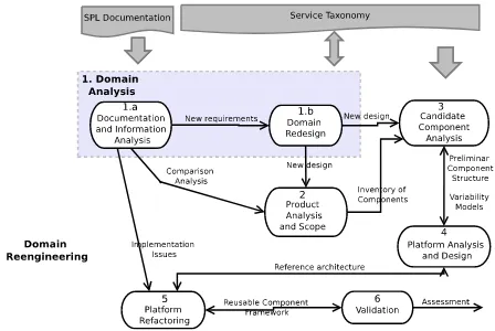
[image:4.595.309.533.69.219.2]In this section we detail the main activities and practices involved in our reengineering process in order to restructure the previous SPL. Figure 1 presents graphically these activities with the two main information sources involved, theSPL Doc-umentation, which involves the analysis and de-sign of the previous SPL; and the Service Tax-onomy, containing the standard services defined in the geographic domain and particularly the
Figure 1: Activities of the Reengineering Process
marine ecology subdomain. The first two activ-ities of the process are part of thedomain anal-ysisphase in which the geographic domain is an-alyzed and designed. Then, the other five activ-ities are specific for the SPL reenginering. It is important to highlight that the activities follow a collaborative approach in which a reengineering team must be involved. This team should be a multi-disciplinary one involving informatics (soft-ware engineers and developers) and domain ex-perts. At the same time, as in the previous SPL implementation we had already applied an open source approach, we faced this reengineering pro-cess based on open source development principles ([16, 17]). Thus, aspects as distribution, iteration and reusability were strongly considered during the execution of the activities.
1) Domain Analysis:
• Motivation: In the previous SPL we had to face some problems during the domain analysis activities. Firstly, as we were dis-tributed in different cities (software engineers and developers live in Neuqu´en and biologists in San Antonio Oeste and Puerto Madryn, which means a distance of 500 kms between both groups) the communication did not work well. Collaborative tools helped us to overcome this problem; however the real problem was having different vocabularies and preconceptions. It made us to misunder-stand requirements and waste precious time during face-to-face meetings.
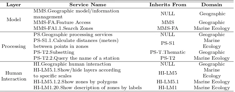
next tasks in the process. At the same time, we implemented specific mechanisms to guar-antee a fluent communication among the par-ties. We defined scheduled on-line and face-to-face meetings and we used shared files to work on a same line. In order to solve the problem of misunderstanding, we took ad-vantage of the service taxonomy and func-tional datasheets defined in [15] and used them as a common language and information structure of the functions required. As we de-scribed in Section 3, we created a service tax-onomy according to the ISO 19119 std. This taxonomy was performed by specializing the abstract services of the ISO and classifying them depending on their particular domain or subdomain. The idea of defining these services was to bridge the gap among the different participant’s skills by reducing the wide spectrum of information sharing. At the same time, services were defined to be as general as possible for supporting the range of possible systems developed in the domains. In Table 1 we can see a set of the specialized services according to the architectural layer and the domain level (geographic, oceano-graphic and marine ecology) in which they are included. Services containing a NULL
value in the “inherits from” column corre-spond to the root services in the service tax-onomy (the main categories of the ISO 19119 std.). Also, in the table we can observe some examples of spatial and thematic services. For instance, the PS-S1.1 service calculates the distance in meters between two points (indicated by a user) within specific zones (represented by a layer) of the map. This service specializes the spatial category and belongs to the marine ecology subdomain.
Therefore, in this analysis, the stakeholders analyzed these services and selected the spe-cific ones they needed. In addition, the new requirements, which had not been found in the taxonomy, were then added as new ser-vices and included in the correct place (by agreement, with the consent of all parties concerned).
• Lessons Learned: One of the main benefits of doing the domain analysis activities was the involvement of a multidisciplinary team, necessary for any domain engineering activity, and the manipulation of a standard structure understood by everyone. How-ever, this structure must be sound as well as dynamic at the same time. It means allowing stakeholders to adapt the structure to specific requirements without losing
its core assets. Obviously, each domain has its own characteristics, but we could take advantage of the many standards the geographic domain provides as a basis to define our structure. It helped us not only build a common vocabulary for requirements today, but also for requirements that may come from different organizations, all over the world, in the future. Therefore, we recommend the use of domain standards whenever they exist. In case world-wide standards are not available, it would be highly recommendable to develop in-house standards and/or taxonomies in order to facilitate domain analysis. Works, as presented in [36, 37, 38, 39], proposing novel methodologies to create taxonomies as semantic resources, could be taken into account in order to assist the development.
2) Product Analysis and Scope:
• Motivation: As a consequence of the commu-nication problems during the domain analy-sis activity, the scope of the previous SPL was vaguely defined. The component struc-ture was designed by supporting only a sub-set of services required by the domain and implemented in a widespread way. Thus, the final structure resulted in a set of pseudo-components providing a set of services hardly identifiable.
Table 1: Part of the Service Taxonomy according to the abstraction levels, architectural layers and domains
Layer Service Name Inherits From Domain
Model
MMS.Geographic model/information
management NULL Geographic
MMS-FA.Feature Access MMS Geographic
MMS-FA1.1.Search Zones MMS-FA Marine Ecology
Processing
PS.Geographic processing services NULL Geographic PS-S1.1.Calculate distances (meters)
between points in zones PS-S1
Marine Ecology
PS-T2.Subsetting PS-T.Thematic Geographic
PS-T2.2.Query the name of a station PS-T2 Marine Ecology
Human Interaction
HI.Geographic human interaction NULL Geographic HI-LM5.1.Show/hide layers according
to specific scales HI-LM5
Marine Ecology HI-LM5.1.2.Show zones by polygons HI-LM5.1 Marine Ecology HI-LM1.20.Show description of zones by labels HI-LM1 Marine Ecology
population, changes on geographical distri-butions of species, etc. This generality on the component implementation undermined the easy modifiability and evolution, mak-ing findmak-ing specific functionalities and bugs within each module really difficult. Obvi-ously, this also affected the independence among components making them highly cou-pled.
All these problems found were reflected in a technical report describing, for each pseudo-component, the specific set of implemented services and their dependences with others.
• Lessons Learned: As this activity was mainly focused on performing an analysis of the previous SPL, the main resource used was again the service taxonomy. The mappings among the pseudo-components and standard services allowed the team to identify the set of services provided by each of them and determine which services (required by the platform) were not satisfied.
At the same time, as the communication in this activity was a main limitation, we recommend to put special effort on doing frequent face-to-face and on-line meetings by sharing documents until all members of the team agree with the platform services. Likewise, it is necessary to define clear objectives and commitments with agreed changes in order to avoid an unnecessary waste of time. Novel techniques and method-ologies to be benefited from meetings can be found in several different areas on the Web11
.
11
http://www.ilo.org/public/english/support/lib/ knowledgesharing/meetings.htm
3) and 4) Candidate Component Analy-sis & Platform AnalyAnaly-sis and Design:
• Motivation: The problems identified in the last activity together with the new require-ments of the domain, and the product/ser-vice matrix, motivated a reengineering of the pseudo-component structure to be applied on the SPL architecture (Section 3). In the two activities here, we had to improve the highly coupled design and define specific services for each new component according to the service taxonomy. At the same, we had to abstract away from the underlying technology which had generated a bad design in the previous SPL.
• Solution: To perform these activities, the pseudo-component structure was completely changed giving more importance to the ser-vices’ interactions of the taxonomy and the functionality required by the domain. Here, only the software engineers and developers participated of the activity without interven-tion of user experts. This decision of exclud-ing user experts was substantiated in the fact that the tasks included software development techniques, such as software artifacts, mod-els, etc. Thus, the new reusable components were designed taking the function datasheets as basis, and adapting them to the platform requirements. For example, Figure 2 shows the design model of thequery zone attributes
Table 2: Component Inventory
Pseudo-Components Implemented Services according the service taxonomy Graphical
Interface
HILM5.Hide/show layers HIMM4.Panning & zoom HILM2.Layer scales -HI-MM2.Refreshing
Geographic Feature Management
HI-LM1.Show layer attributes - HI-LM5.1.Show/hide layers according to specific scales - HI-LM6.Editing attributes
Change Detection PST1.1.Determine changes on population of species in different censuses -PS-T1.3.Determine changes of distribution of species in different censuses
Proximity
Analysis PS-S3.3.Obtain geographic features around an specific area Geographic
Statistics PS-S4.Generate statistics of geographic features Feature Access MMS-FA1.Access to geographic feature
Map Access MMS-MA1.Access to georeferenced maps
Figure 2: Design model item of thequery zone attributes datasheet
by table) or the HI-LM1.19 (code zone by la-bels) service depending on specific platform requirements. The same happens with the PS-T2.6 (query the description of zones) ser-vice which can require, alternatively, to show the attribute by labels or tables. At the same time, the functionality needs the services HI-LM.5.1.2 (show zones by poligons) and MMS-FA1.1 (search zones) for searching the zones’ attributes in the geographic database.
Then, we took these reusable components in order to build the final reference architecture of the new SPL. For example, for the query zone attributes functionality, we added the variant services as variabilities on the show zone attributescomponent.
• Lessons Learned: We have learned several as-pects during this activity which worked fine to us. Firstly, and considering team inte-gration, we suggest involving only the stake-holders who better understand methodolo-gies and techniques to be applied. There must be some of them, who were more
in-volved during taxonomy and/or standard adaptation, so they are more familiar with the common vocabulary and its implications. They are the best candidates to be part of the reduced team. Secondly, analyze service interactions to identify recurrent uses with their particularities. From there, extract in-teractions rules and formalize them through a committed document. In our case, this doc-ument was the function datasheet, which es-tablished a skeleton to start modeling and de-signing common and variable services (trans-lated later into components). Of course, the use of domain standards is valuable at this step too.
Finally, the design of service interactions should be kept independent from any kind of technology. Technology constraints will be analyzed during the next step, when con-crete components are designed according to an implementation platform. So, we should avoid thinking of technology limitations at this point. This is really helpful when look-ing for recurrent interactions that depend on domain requirements.
5) Platform Refactoring:
the variabilities of each functionality. These two tasks were performed towards improv-ing the previous coupled code, hard interface separation, inefficient variability implementa-tion etc.
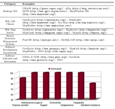
• Solution: The first task was related to the geographic domain and the geographic tools available. As we followed an open source development, we had to analyze the wide set of open source tools available for the domain. At the same time, it was important to understand the nature of GIS and the functions of each open source component in order to guarantee the selection process and then the implementation success ([40]). To do so, we began searching and analyzing literature and documentation of geographic tools to understand their behavior. This task was really hard and complex because there exists a really huge number of geo-graphic tools. Fortunately several works published on the Web agree on a classifica-tion of geographic tools into five categories. Table 3 shows these categories exemplified by open source tools. It is important to highlight that some tools fit in more than one category because they can be used to implement functionalities of either of them. For example, we can see in the table that MapBender can be used as a web client or as a development framework.
Our evaluation was based on several aspects that must be supported by the selected tools. The aspects analyzed were:
– Features provided: Which are the fea-tures the tool is intended to provide? For each layer of our architecture and considering the functionality each com-ponent should implement, we listed the needed features, such as possibility of defining spatial datatypes and opera-tions, support to raster analysis, etc., which were later used to analyze the de-gree of support of each tool.
– Maintenance/Longevity: Is the tool be-ing maintained? Here we evaluated whether the tool was actively main-tained, and that it would be maintained far into the future.
– Support: Does the tool provide a good documentation? Are administra-tor manuals, reference guides, and fo-rums available and clear enough? Here we evaluated the documentation pro-vided by the tool as well as the active
discussion on different forums of partic-ularities about its features.
– Extensibility: Is the tool easy to ex-tend? Here we evaluated whether the tool would be easily customizable and extensible to add new features unsup-ported by its original source.
– Independence: Is the tool independent? Here we analyzed the software depen-dences required by the tool. We eval-uated with a higher score those tools which did not need other tools to work.
– Integrability: Is the tool easily inte-grable with other tools? We analyzed here whether the tool had the ability of working with others. Thus, we mea-sured the possibility of the tools of in-teracting among them according to our architectural levels and the component-based approach. A high value indicated that the tool provided communication mechanisms to be integrated.
– Standard-compliance: Is the tool com-pliant with GIS standards proposed by the OGC and/or ISO 19100? We evalu-ated the tools considering the standards they support, such as WFS and/or WMS services12,13.
To evaluate these aspects we used the docu-mentation provided by each tool including user and administration guides, wikis and forums in which they had been referenced, and projects in which they had been applied. Also, we took advantage of several Web sites with comparisons among open source tools within the geographic domain, such as those provided by the OSGEO Foundation14
. Thus, we scored each tool according to the previous aspects obtaining different results. In Figure 3 we can see the score obtained by OpenLayers according to each aspect evaluated.
It is important to highlight here that the most difficult evaluation was in the inte-grability aspect due to the complexity to determine in this stage the real compatibility among the tools. Before evaluating this aspect, we made a preselection of the tools to make the final selection simpler. Thus, in some cases, some tools that had been selected in the preselection phase, were then discharged due to their incompatibilities
12
http://www.opengeospatial.org/standards/wms 13
http://www.opengeospatial.org/standards/wfs 14
Table 3: Classification and examples of GIS open source software
Category Examples
Desktop GIS
GRASS (http://grass.osgeo.org/) - uDig (http://udig.refractions.net/) -QGIS (http://www.qgis.org/es/site/) - MapWindow GIS
(http://www.mapwindow.org/)
Web GIS Clients
OpenLayers (http://openlayers.org/) - Mapbender
(http://www.mapbender.org/) - Ka-Map (http://ka-map.maptools.org/)
-MapBuilder (http://www.mapbuilder.net/)
Web Map Server
GeoServer (http://geoserver.org/) - MapServer (http://mapserver.org/) -MapGuide (http://mapguide.osgeo.org/) - Mapnik (http://mapnik.org/) Spatial
Database Management
Systems
PostGIS (http://postgis.net/) - MySQL-GIS (http://dev.mysql.com/)
Software Development
Frameworks
GeoMajas (http://www.geomajas.org/) - MapFish (http://mapfish.org/) -MapBender - FDO (http://fdo.osgeo.org/)
Software Libraries and
Extensions
GDAL & OGR (http://www.gdal.org/) -GeoTools
(http://www.geotools.org/) - FDO
Figure 3: Results of the evaluation of the OpenLayer according to our evaluation aspects
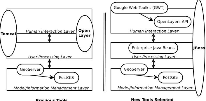
to work with others. To do so, we had to install all the preselected tools and run some test cases in which they had to work together. In addition, the different versions of each tool had to be evaluated because some new versions of the tools did not work well with others, but older versions did. Thus, we finally arrived into a selected set of tools that implement services for each architectural layer. In Figure 4 we show the tools used in the previous SPL against the new set of selected tools.
Based on this new set of tools, we performed the second task within the Platform Refac-toring activity. In this task, we had to refac-tor the old code to adapt it to the new com-ponent approach according to the program-ming technology and tools selected. As we previously described in Section 3, the
previ-ous SPL used PostGIS, GeoServer and Open-Layers to implement services within the lay-ers of the architecture. In Figure 4 we can see that the two first layers (human interaction and user processing) were implemented using OpenLayers in its javascript version running over an Apache Tomcat15
web server. As the interface was coupled to the processing, the services were implemented as javascript libraries and HTML pages. With the new se-lected tools, we could separate the interface of the processing by using the GWT16
frame-work to implement javascript code. The GWT uses OpenLayer as a library to add geographic abilities to the code. Then, we used Enterprise Java Beans ([41]) technology to implement the processing services which interact with the model and interface
ser-15
http://tomcat.apache.org/ 16
Figure 4: Comparison of the previous and the new tools selected
vices to fulfill specific functionalities. Finally, the tools applied for the last architectural layer were the same than in the previous SPL (GeoServer and PostGIS). At the same time, another particularity of the new set of tools is that they run over a JBoss17
application server which allowed us to run EJB compo-nents.
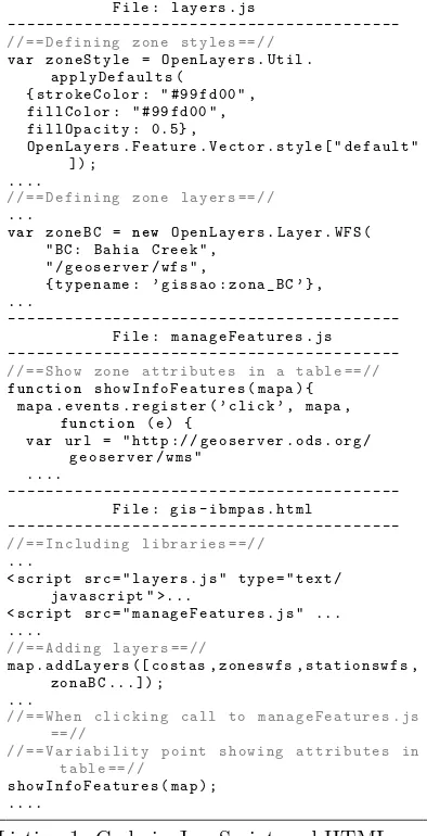
Thus, with these new set of tools and the def-inition of the new underlying technology, we began the refactoring task. In order to show some work made for this activity, we present Listing 1 and 2. In Listing 1 we can see an extract of the set of files in javascript and HTML code to implement thequery zone at-tributes functionality. Then, in Listing 2 we can see how the code was refactored to repre-sent the same functionality but implemented according to our architecture and the tech-nology chosen. As we can see there are many differences between them. First of all, in the previous SPL we can see that all the process-ing and variability management were repre-sented in the html web page. At the same time, the javascript files, one for defining the layers (layers.js) and the other for con-structing the table with the zone attributes (manageFeatures.js) access the database for querying the zone through geoserver services. Each layer of the system (such as zones, stations, etc.), which must be visualized in a product of the SPL, must be coded and called by an HTML web page. Thus, we can see the code is highly coupled making the web pages contain all the processing of dif-ferent functionalities of the platform together with the possible variant points.
In the new SPL (Listing 2), we divided
17
http://www.jboss.org/
the functionality into different components which perform specific services. Therefore, as we have showed in Figure 2a), three com-ponents of the three architectural layers im-plement services to fulfill the functionality required. At the same time, the variability was differently represented adding java anno-tations technology18
. Each java annotation describes a set of features which will be ap-plied at the instantiation time. Thus, the variant points were represented by dummy methodswhich will be fulfilled if the variabil-ity is chosen.
The output of the Platform Refactoring ac-tivity was a set of reusable components im-plemented, which built the SPL platform.
• Lessons Learned: Selecting open source tools and the underlying technology is always a complicated task that depends on many factors. Far from defining here a whole process for selecting software, our lessons are more focused on particular aspects of the process. In our case, the main challenge was to define the appropriate evaluation characteristics that allow developers imple-ment the architectural constraints defined in the new SPL. On one hand, and similarly to other domains, the geographic one offers a huge number of open tools, which can turn the selection into a chaotic unstructured process. To mitigate this fact, we look this as an opportunity to find more appropriate tools by prioritizing characteristics. We put more emphasis on three of them: standard-compliance, extensibility and integrability. The first one is important to design decisions that made us to follow standards whenever
18
it is possible. The second one is important because we prioritized preserving architec-tural constraints and component structure, so we needed the possibility of extending the selected tools in case they were not able to fulfill our expectations. Finally, intregrabil-ity was relevant for achieving an adequate performance when running the selected tools all together. This characteristic was tested twice to be certain of getting the right combination of selected tools.
-File : layers . js
-// == Defining zone styles ==-//
v a r zoneStyle = OpenLayers . Util .
applyDefaults ( { strokeColor : " #99 fd00 " , fillColor : " #99 fd00 " , fillOpacity : 0.5} ,
OpenLayers . Feature . Vector . style [ " default " ]) ;
....
// == Defining zone layers ==//
...
v a r zoneBC = n e w OpenLayers . Layer . WFS ( " BC : Bahia Creek " ,
" / geoserver / wfs " ,
{ typename : ’ gissao : zona_BC ’} , ...
-File : manageFeatures . js
-// == Show zone attributes in a table ==-//
f u n c t i o n showInfoFeatures ( mapa ) { mapa . events . register ( ’ click ’ , mapa ,
f u n c t i o n ( e ) {
v a r url = " http :// geoserver . ods . org / geoserver / wms "
....
-File : gis - ibmpas . html
-// == Including libraries ==-//
...
< script src = " layers . js " type = " text / javascript " >...
< script src = " manageFeatures . js " ... ....
// == Adding layers ==//
map . addLayers ([ costas , zoneswfs , stationswfs , zonaBC ...]) ;
...
// == When clicking call to manageFeatures . js ==//
// == Variability point showing attributes in table ==//
showInfoFeatures ( map ) ; ....
Listing 1: Code in JavaScript and HTML
Therefore, in addition to following a selection process, prioritizing characteristics according to domain and design decisions should drive the screening and evaluation of candidate tools.
On the other hand, code refactoring implied rewriting several lines of code and creating a completely new method for representing variability. To do so, we created templates and transformation guidelines for coding components according to each architectural
level. These templates were annotated to help find and instantiate the component variability. Then, documenting refactoring through standard documentation helped us keep activities under control as well as implement the refactoring itself.
-Show Zone Attribute Component
-// == AsynCall to Show Zone Attribute Component ==//
callback = new AsyncCallback < List < WFSManipulation > >() {
public void onSuccess ( List < WFSManipulation > result ) { âĂę .
public void onClick ( ClickEvent arg0 ) { ...
i f ( check . getValue () ) {
mapaBase . addMapLayer ( map , wfsZona ) ; v a r i a n t P o i n t I n s e r t T a b l e Z o n a ( wfsZona .
getName () ) ; ...}
// == Variant Point to to show attributes in a table format ==//
@Variability ( service ={ " Show attibutes in a Table " } ,
type ={ " optional " } , function = { " call ZoneTable " } )
private void v a r i a n t P o i n t I n s e r t T a b l e Z o n e ( String nameZona ) {
...{
[image:11.595.325.528.147.712.2]public void onSuccess ( List < String > result ) {
table_Zone . AddFile ( result ) ;}
...
// == Call to Query Zones Component ==//
Servicio . QueryZone ( idZone , callback ) ; }
...
}; // == end Asyncall ==//
-Query Zone Component
-public List < String > QueryZone ( String idZone , String BD ) {
...
List < String > zone = new ArrayList < String >() ;
// == Search zone in DB through the Search Zone Component ==//
ResultSet respuesta = SearchZones . Search ( idZone , Zones ) ;
try {
respuesta . next () ;
zone . add ( respuesta . getString ( " codigo " ) ) ;
zone . add ( respuesta . getString ( " descripcion " ) ) ;
...
-Search Zone Component
-public Resultset SearchZones ( String idZona , String BD ) {
// == Real access to DB ==//
BDAcceso datos = new BDAcceso ( BD ) ; datos . conectarse () ;
String select =
" select * from Zonas Where codigo = ’ " + idZona + " ’" ;
....}
Listing 2: New code by following a component-based approach
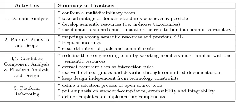
[image:11.595.88.285.231.616.2]Table 4: Summary of good practices within each reengineering activity
Activities Summary of Practices
1. Domain Analysis
* conform a multidisciplinary team
* take advantage of domain standards whenever is possible * develop semantic resources (i.e. in-house taxonomies)
* use domain standards and semantic resources to build a common vocabulary
2. Product Analysis and Scope
* mappings among semantic resources and previous SPL * frequent meetings
* clear definition of goals and commitments
3,4. Candidate Component Analysis & Platform Analysis
and Design
* redefine the reengineering team by selecting members more familiar with the semantic resources
* extract recurrent uses as interaction rules
* use well-defined guides and describe through committed documentation * keep design independent from technology constraints
5. Platform Refactoring
* define a selection process of open source tools
* put emphasis on standard-compliance, extensability and integrability * define templates for implementing components
some regression tests in order to verify the previ-ous functionalities were supported and the new ones run correctly. However, we must still work-ing on this activity in order to fully analyze the functionalities of the new SPL with respect to the service taxonomy and datasheets defined in the design activities.
5
Discussion
Our main goals for a reengineering process were oriented towards reaching highly cohesive and in-dependent designs that minimize coupling among services. To do so, we defined and applied standard resources, domain-services (placed on the service taxonomy) and function datasheets. These resources helped us organize the marine ecology domain (and some of its superdomains) into a set of fine-grained services, which can inter-act in different ways to satisfy the requirements of this domain. At the same time, as the stan-dard services and the datasheets were defined by applying guides and rules proposed by geographic information standards, the reference architecture, created after the reengineering process, imposed well-defined design decisions for future extensions. In addition, this software design enforced special requirements with respect to implementation is-sues constraining the underlying technology.
In a previous work [42], we have focused on the validation process of the new SPL analyzing aspects such as time required for the construction of each product, percentage of bugs that were found in reusable and specific components, and time required in the construction of product-specific components. In the analysis we could see important improvements in time and cost; so we considered that extracting hints from our
[image:12.595.97.495.125.294.2]experiences might result interesting to people involved in similar reengineering efforts. Thus, in Table 4 we summarize the recommendations that might help stakeholders to perform the activities.
6
Conclusion and Future Work
In this article we have described our work on reengineering a software product line within the geographic domain. We have presented an orig-inal SPL that combines the use of domain stan-dards together with open source software; how-ever, this design is deficient with respect to sepa-ration of concerns when designing and implement-ing on a concrete platform. These deficiencies came from an incorrect selection and use of the underlying technology and a non-standardized design and application rules. Thus, we have showed how the application of some good prac-tices, such as the definition of standard services, user’s guides (defined as function datasheets) and well-design structures, have improved the soft-ware design and implementation of the reengi-neered SPL.
In order to summarize our work, we have ex-tracted a set of good practices coming from our experiences performing each activity of the reengi-neering process as well as from the original SPL development.
As a final conclusion, the reengineered SPL has showed how some bad habits, highly promoted sometimes such as fast implementations, coupled code, circular dependences, etc., can be avoided consequently improving reusability capabilities.
Our future work is focused on evaluating the final architecture more formally and improving the mechanisms for variability management of our component-based structures.
References
[1] J. Bayer, O. Flege, P. Knauber, R. Laqua, D. Muthig, K. Schmid, T. Widen, and J. De-Baud, “Pulse: A methodology to develop software product lines,” in Proceedings of the 1999 Symposium on Software Reusability, SSR ’99, (New York, NY, USA), pp. 122–131, ACM, 1999.
[2] J. Bosch, Design and use of software archi-tectures: adopting and evolving a product-line approach. New York, NY, USA: ACM Press/Addison-Wesley Publishing Co., 2000.
[3] P. C. Clements and L. Northrop, Soft-ware Product Lines: Practices and Patterns. Boston, MA, USA: Addison-Wesley Long-man Publishing Co., Inc., 2001.
[4] M. Matinlassi, “Comparison of software product line architecture design methods: Copa, fast, form, kobra and qada,” in Pro-ceedings of the ICSE ’04: 26th International Conference on Software Engineering, (Wash-ington, DC, USA), pp. 127–136, IEEE Com-puter Society, 2004.
[5] K. Pohl, G. B¨ockle, and F. J. v. d. Linden,
Software Product Line Engineering: Founda-tions, Principles and Techniques. Secaucus, NJ, USA: Springer-Verlag New York, Inc., 2005.
[6] M. Fajar, K. Hisazumi, T. Nakanishi, and A. Fukuda, “Introducing software product line development for wireless sensor/actua-tor network based agriculture systems,” in
AFITA 2010 International Conference on Quality Information for Competitive Agri-cultural Based Production System and Com-merce, (Bogor, Indonesia), pp. 83–88, IPB (Bogor Agricultural University), 2010.
[7] F. van der Linden, K. Schmid, and E. Rommes, Software Product Lines in Ac-tion: The Best Industrial Practice in Prod-uct Line Engineering. Secaucus, NJ, USA: Springer-Verlag New York, Inc., 2007.
[8] J. Bosch and P. M.. Bosch-Sijtsema, “Intro-ducing agile customer-centered development in a legacy software product line,” Software Practice & Experience, vol. 41, pp. 871–882, July 2011.
[9] W. Jirapanthong, “Experience on re-engineering applying with software product line,” CoRR, vol. abs/1206.4120, 2012.
[10] D. B.. Smith, L. O’Brien, and J. Bergey, “Using the options analysis for reengineering (oar) method for mining components for a product line,” in Second International Con-ference of Software Product Lines, pp. 316– 327, 2002.
[11] Y. Wu, X. Peng, and W. Zhao, “Architec-ture evolution in software product line: An industrial case study,” in Proceedings of the 12th International Conference on Top Pro-ductivity Through Software Reuse, ICSR’11, (Berlin, Heidelberg), pp. 135–150, Springer-Verlag, 2011.
[12] G. Zhang, L. Shen, X. Peng, Z. Xing, and W. Zhao, “Incremental and iterative reengi-neering towards software product line: An industrial case study,” in Proceedings of the 2011 27th IEEE International Conference on Software Maintenance, ICSM ’11, (Washing-ton, DC, USA), pp. 418–427, IEEE Com-puter Society, 2011.
[13] P. Pernich, A. Buccella, A. Cechich, S. Doldan, and E. Morsan, “Reusing geo-graphic e-services: A case study in the ma-rine ecological domain,” in Software Ser-vices for e-World (W. Cellary and E. Es-tevez, eds.), vol. 341 ofIFIP Advances in In-formation and Communication Technology, pp. 193–204, Springer Boston, 2010.
[14] P. Pernich, A. Buccella, A. Cechich, S. Doldan, E. Morsan, M. Arias, and M. Pol’la, “Product-line instantiation guided by subdomain characterization: A case study,” Journal of Computer Science and Technology, Special Issue 12(3), vol. 12, no. 3, pp. 116–122, 2012.
[15] A. Buccella, A. Cechich, M. Pol’la, M. Arias, S. Doldan, and E. Morsan, “Marine ecol-ogy service reuse through taxonomy-oriented SPL development,” Computers & Geo-sciences, vol. 73, no. 0, pp. 108 – 121, 2014.
[17] M. Sojer and J. Henkel, “Code reuse in open source software development: Quantitative evidence, drivers, and impediments,” Jour-nal of the Association for Information Sys-tems, vol. 11, no. 12, 2010.
[18] L. Chen and M. A.. Babar, “A systematic re-view of evaluation of variability management approaches in software product lines,” In-formation and Software Technology, vol. 53, pp. 344–362, Apr. 2011.
[19] S. Mahdavi-Hezavehi, M. Galster, and P. Avgeriou, “Variability in quality at-tributes of service-based software systems: A systematic literature review,” Informa-tion and Software Technology, vol. 55, no. 2, pp. 320 – 343, 2013. Special Sec-tion: Component-Based Software Engineer-ing (CBSE), 2011.
[20] K. Czarnecki, Domain Engineering, ch. 3. John Wiley & Sons, Inc., 2002.
[21] M. Harsu, “A survey on domain engineering,” Report 31, Tampere University of Technol-ogy, 2002.
[22] L. B. Lisboa, V. C. Garcia, D. Lucr´edio, E. S. de Almeida, S. R. de Lemos Meira, and R. P. de Mattos Fortes, “A systematic review of domain analysis tools,” Information and Software Technology, vol. 52, no. 1, pp. 1–13, 2010.
[23] J. Bayer, , J. Girard, M. W¨urthner, J. De-Baud, and M. Apel, “Transitioning legacy assets to a product line architecture,” SIG-SOFT Softw. Eng. Notes, vol. 24, no. 6, pp. 446–463, 1999.
[24] C. Stoermer and L. O’Brien, “Map - min-ing architectures for product line evalu-ations,” in Proceedings of the Working IEEE/IFIP Conference on Software Archi-tecture, WICSA ’01, (Washington, DC, USA), pp. 35–, IEEE Computer Society, 2001.
[25] M. A.. Laguna and Y. Crespo, “A system-atic mapping study on software product line evolution: From legacy system reengineering to product line refactoring,”Science of Com-puter Programming, vol. 78, no. 8, pp. 1010– 1034, 2013.
[26] W. Fenske, T. Th¨um, and G. Saake, “A taxonomy of software product line reengi-neering,” in Proceedings of the Eighth Inter-national Workshop on Variability Modelling of Software-Intensive Systems, VaMoS ’14,
(New York, NY, USA), pp. 4:1–4:8, ACM, 2013.
[27] M. A.. Noor, R. Rabiser, and P. Gr¨unbacher, “Agile product line planning: A collaborative approach and a case study,”Journal of Sys-tems and Software, vol. 81, no. 6, pp. 868 – 882, 2008. Agile Product Line Engineering.
[28] H. P. Breivold, S. Larsson, and R. Land, “Migrating industrial systems towards soft-ware product lines: Experiences and obser-vations through case studies,” in Proceed-ings of the 2008 34th Euromicro Conference Software Engineering and Advanced Appli-cations, SEAA’08, (Washington, DC, USA), pp. 232–239, IEEE Computer Society, 2008.
[29] D. Faust and C. Verhoef, “Software prod-uct line migration and deployment,” Soft-ware Practice & Experiences, vol. 33, no. 10, pp. 933–955, 2003.
[30] K. Kang, M. Kim, J. Lee, and B. Kim, “Feature-oriented re-engineering of legacy systems into product line assets: A case study,” in Proceedings of the 9th Interna-tional Conference on Software Product Lines, SPLC’05, (Berlin, Heidelberg), pp. 45–56, Springer-Verlag, 2005.
[31] M. Fowler, Refactoring: Improving the De-sign of Existing Code. Boston, MA, USA: Addison-Wesley Longman Publishing Co., Inc., 1999.
[32] S. Apel and C. K¨astner, “An overview of feature-oriented software development,”
Journal of Object Technology, vol. 8, no. 5, pp. 49–84, 2009.
[33] S. Schulze, T. Th¨um, M. Kuhlemann, and G. Saake, “Variant-preserving refactoring in feature-oriented software product lines,” in
Proceedings of the Sixth International Work-shop on Variability Modeling of Software-Intensive Systems, VaMoS ’12, (New York, NY, USA), pp. 73–81, 2012.
[34] K. Czarnecki, S. Helsen, and U. W. Eise-necker, “Formalizing cardinality-based fea-ture models and their specialization,” Soft-ware Process: Improvement and Practice, vol. 10, no. 1, pp. 7–29, 2005.
[36] D. Bruno and H. Richmond, “The truth about taxonomies,” Information Manage-ment Journal, vol. 37, no. 2, 2003.
[37] C. E. B. Choksy, “8 steps to develop a tax-onomy,” Information Management Journal, vol. 40, no. 6, pp. 30–41, 2006.
[38] I. Hunink, E. Rene, S. Jansen, and S. Brinkkemper, “Industry taxonomy engi-neering: the case of the european software ecosystem,” inProceedings of the Fourth Eu-ropean Conference on Software Architecture: Companion Volume, ECSA ’10, (New York, NY, USA), pp. 111–118, ACM, 2010.
[39] R. C. Nickerson, U. Varshney, J. Munter-mann, and H. Isaac, “Taxonomy develop-ment in information systems: Developing a taxonomy of mobile applications,” in 17th
European Conference on Information Sys-tems, ECIS 2009, (Italy), pp. 1138–1149, 2009.
[40] D. A.. Garbin and J. L.. Fisher, “Open source for enterprise geographic information systems,” IT Professional, vol. 12, no. 6, pp. 38–45, 2010.
[41] B. Burke and R. Monson-Haefel,Enterprise JavaBeans 3.0 (5th Edition). O’Reilly Media, Inc., 2006.