Design of a Compact Dual-band Microstrip RFID Reader
Antenna
Hafid TIZYI1,*, Fatima RIOUCH1, Abdellah NAJID1, Abdelwahed TRIBAK1, Angel Mediavilla2
1STRS Lab., National Institute of Posts and Telecommunications – INPT. Rabat – Morocco 2DICOM, University of Cantabria Santander, Spain
E-mail: [email protected] Abstract- In this paper, we propose a dual band
Radio Frequency Identification (RFID) reader antenna. The reader antenna operates at 2.45GHz and 5.8GHz. It has two resonances, the first one in the radiation patch, and the second one in the protruding stub located at the ground plane. The radiating patch of the present compact antenna has the dimensions of 15.6mm x 8.8mm. The matching techniques using stub tuning are adopted in this work. A good impedance bandwidth of 148.48MHz and 204.85MHz has been achieved for 2.45GHz and 5.8GHz respectively while the return loss 𝐒𝟏𝟏< −10dB. The proposed antenna is simple and compact in size, providing broadband impedance matching and an appropriate gain, 1.92dBi and 3.385dBi for the lower and upper bands respectively. The comparison between measured and simulated results shows a good agreement, which validates the proposed concept.
Index Terms- RFID reader antenna, dual band antenna, WLAN, stub tuning, compact micro-strip antenna.
I. INTRODUCTION
The concept of RFID (Radio Frequency Identification) appeared the first time during the Second World War. It was related to radio and radar development to determine whether planes arriving in the British airspace were friends or foes. This system was called IFF (Identify Friend or Foe) [1]. The first idea of RFID of objects and remote control of the device was introduced in late 1948 by Harry Stockman [2]. RFID became the universal technology and its applications have been found in more advanced areas such as distribution, logistics, homeland and personal security, distributed sensor networks [3] and bio-engineering [1]. Compared to the barcode and
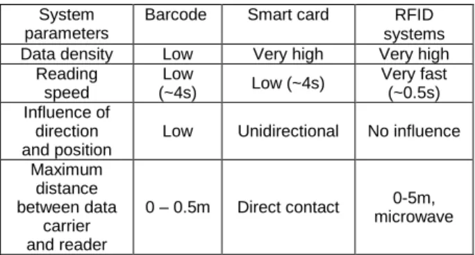
smart card technologies, RFID systems have the advantages of rapid identification, flexible method and high intelligent degree as shown in Table 1. Furthermore, it can operate under a variety of environmental conditions [4].
Table 1: Comparison between RFID and other identification systems
System parameters
Barcode Smart card RFID systems Data density Low Very high Very high
Reading speed Low (~4s) Low (~4s) Very fast (~0.5s) Influence of direction and position
Low Unidirectional No influence Maximum
distance between data
carrier and reader
0 – 0.5m Direct contact microwave 0-5m,
A basic RFID system is composed of two components, an RFID transponder (tag) and an interrogator or reader. The RFID interrogator transmits a radio frequency interrogation signal through the reader antenna and receives the backscattered signal from the transponder in the field of the antenna. The block diagram of an RFID system is shown in Figure 1.
As shown in Fig.2, several frequency bands have been standardized for RFID applications. Some advantages and disadvantages are associated with using each frequency band [5]:
RFID systems operating at low frequencies (LF) provide a low data rate and short reading ranges, compared to RFID systems operating at high
frequency (HF) and UHF band, which offer high data rate and high reading ranges.
Fig.1. Block Diagram of an RFID System
Fig.2. RFID frequencies
Furthermore, as the RFID applications rise in the microwave frequency, the reader antenna design becomes critical. In this case, micro-strip antennas are an attractive choice due to their advantages of low profile, light weight, and low manufacturing costs.
Various applications of RFID systems demand different frequencies. Therefore, designing a reader antenna that operates at many bands can solve the problem of using various applications with a single antenna. For this reason, many dual band antennas of 2.45 and 5.8GHz have been developed and discussed in the literature. A single layered, dual band micro-strip reader antenna composed of a single patch on the top layer and slots on the radiating edges is presented in [5] with a dimension of 19×29mm for the radiating patch. A dual-band bidirectional dipole array antenna
with a dimension of 80×80mm is proposed [6]. In [7], a modified annular ring slot antenna with a size of 50×50mm is reported. As can be seen in the works cited above, many of these antennas are not compact and in some cases may be difficult to fabricate.
In this paper, we present a simple and compact micro-strip antenna using a rectangular shape with two resonance paths, one on the radiating element and the other in the ground plane. For the proposed antenna, a low cost of mass production is achieved by using a compact single layered antenna with an FR4 substrate.
II. ANTENNA DESIGN
Fig.3 shows the geometry of the proposed antenna. It is composed of a single patch at the top of a rectangular shape and two stubs. The first stub is in the partial ground plane and the second, called Stub Tuning, is perpendicular to the micro-strip feedline. The antenna is fabricated on an FR4 substrate with relative permittivity εr=4.4 and
thickness h=1. 6mm. The antenna is fed with a micro-strip line of 50Ω.
Fig.3. Geometry and dimensions of the proposed antenna (a) back view, (b) top view, (c) side view
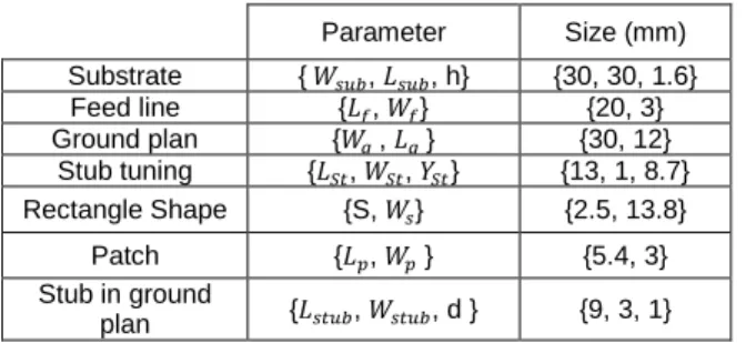
Table 2: Parameters of the proposed antenna Parameter Size (mm) Substrate { 𝑊𝑠𝑢𝑏, 𝐿𝑠𝑢𝑏, h} {30, 30, 1.6} Feed line {𝐿𝑓, 𝑊𝑓} {20, 3} Ground plan {𝑊𝑔 , 𝐿𝑔 } {30, 12} Stub tuning {𝐿𝑆𝑡, 𝑊𝑆𝑡, 𝑌𝑆𝑡} {13, 1, 8.7} Rectangle Shape {S, 𝑊𝑠} {2.5, 13.8} Patch {𝐿𝑝, 𝑊𝑝 } {5.4, 3} Stub in ground plan {𝐿𝑠𝑡𝑢𝑏, 𝑊𝑠𝑡𝑢𝑏, d } {9, 3, 1}
Two resonance paths are clearly visible in the antenna, the first one in the rectangular shape and the patch of the radiating element, and the second in the protruding stub of the ground plane. We also use stub tuning in the feedline for matching. The dimensions of our proposed antenna according to the Fig. 3 are shown in Table 2.
The initial geometry of the proposed antenna as illustrated in Fig. 5, was firstly designed using the following classical equations [8].
𝑤 =
2𝑓𝑐 0√
𝜀𝑟+1 2(1)
𝐿 =
2𝑓𝑐 0√𝜀𝑟− 2∆𝑙
(2)
Ɛ
eff=
Ɛr+1 2+
Ɛr+1 2√1 +
10h w(3)
∆𝑙 = 0.412ℎ
(𝜀𝑟+0.3)( 𝑤 ℎ+0.264) (𝜀𝑟−0.258)(𝑤ℎ+0.8)(4)
W is the width of the patch, L is the length of the patch, εr is the dielectric constant of the substrate, Ɛeff is the effective dielectric constant, f0 is the target frequency and h is the thickness of the substrate. The width Wf of feedline is calculated
using equation (5), where Z0 is the impedance of the feedline (Z0= 50Ω).
𝑍
0=
120π√Ɛeff∗[Wfh+1.393+0.667 ln(Wfh+1.444)
(5)
The matching techniques using a single short-circuited length of transmission line or stub tuning connected in series with the feedline are applied in this work. In the single stub tuning, the two adjustable parameters are the distance 𝑑 and the reactance provided by the series stub as described in Fig. 4. The admittance Y at the distance d from the load ZL is [9]:
Y = 1
Z With
Z = R + jX = Z0ZL+jZ0t
Z0+jZLt , t=tan βd (6) (−jX) is the reactance of the stub tuning and ZLis
the load impedance with: ZL =Y1 L and YL= GL+ jBL So R = GL(1+t 2) GL2+(BL+Y0t2) (7a) And X =GL 2t−(Y 0−tBL)(BL−tY0) Y0[GL2+(BL−tY0)2] (7b) d is chosen such that R = Z0=Y1
0 Equation (7a) gives:
𝑌0(𝐺𝐿− 𝑌0)𝑡2− 2𝐵𝐿𝑌0𝑡 + (𝐺𝐿𝑌0− 𝐺𝐿2− 𝐵𝐿2) = 0 Solving for t gives:
t =BL √GL[((Y0−GL) 2+B L2]/Y0 − + GL−Y0 for GL≠ Y0 t = −BL/2Y0 for GL= Y0
d λ= 1 2πtan −1t for t≥0 (8a) d λ= 1 2π(π + tan −1t) for t<0 (8b)
When t is determined, the length L of the short circuit stub is calculated as follows:
L =−12πtan−1(X
Z0) (9) If the length given by equation (9) is negative, we can add λ2 to obtain a positive result.
Fig.4. Single series stub tuning
The ZL of the radiating element in the proposed
antenna can be calculated using this equation: 𝑍𝑙 = (𝑍𝑟− 𝑍𝑠) + 𝑍𝑝 (10) With: 𝑍𝑟 = 90 𝜀𝑟2 𝜀𝑟−1( 𝐿 𝑟 𝑊𝑟) 2
is the impedance of the rectangle element. 𝑍𝑠 = 90 𝜀𝑟 2 𝜀𝑟−1( 𝑆 𝑊𝑠) 2
is the impedance of the slot element. 𝑍𝑝= 90 𝜀𝑟2 𝜀𝑟−1( 𝐿𝑝 𝑊𝑝) 2
is the impedance of the patch element.
Fig.5. The initial geometry of the proposed antenna
III. RESULTS AND DISCUSSION The antenna performance was studied by using the computer simulation technology (CST) microwave studio. To validate our use of design software CST, we designed and simulated the same structure as high-frequency structural simulator HFSS software whose numerical analysis is based on the finite element method. Fig. 5 illustrates the reflection coefficient obtained from both simulation tools.
Fig.6. Simulated return loss for the proposed antenna
The reflection coefficient curve shows that the designed antenna resonates at 2.45 GHz with a bandwidth of 148.48 MHz (2.372–2.521 GHz) and at 5.8 GHz with an impedance bandwidth of
204.65MHz (5.7136–5.921GHz). The maximum return loss of -30dB and -41.225dB is obtained at the resonant frequencies of 2.45GHz and 5.8GHz respectively. Moreover, we note a good agreement between both simulation results.
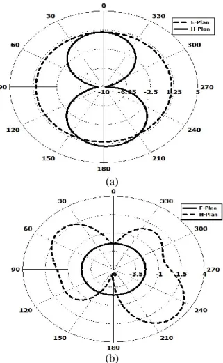
Fig.7 shows the radiation patterns of the proposed antenna at 2.45GHz and 5.8GHz. We can see that the antenna offers an omnidirectional radiation pattern at 𝑓1=2.45GHz, with a maximum gain of
1.92dBi. At 𝑓2=5.8GHz, the radiation pattern is
directional along 230°, with a maximum gain of 3.385dBi.
(a)
(b)
Fig.7. Simulation of E and H plane radiation pattern of the proposed antenna at a) 2.45GHz, and b) 5.8GHz
IV. PARAMATRIC STUDY
The purpose of this study is to show the effects of different elements of the antenna on return loss. The parametric study of the proposed antenna is performed by using computer simulation technology (CST) microwave studio.
Fig. 8 shows the return loss of successive values of the patch’s length ( 𝐿𝑝) when the other parameters remain constant. From this figure, it can be seen that when ( 𝐿𝑝) increases the performance of the first resonant frequency 𝑓1=
2.45 GHz degrades but remains nearly constant at 2.45GHz. On the other hand, the second resonant frequency 𝑓2=5.8 GHz moves to the left, which means that the second resonance decreases when 𝐿𝑝 increases.
Fig.8. The effects on return loss for different lengths of the Patch
Similarly, Fig. 9 shows the return loss for different values of stub’s length ( 𝐿𝑠𝑡𝑢𝑏) when other parameters remain constant. It can be seen that when 𝐿𝑠𝑡𝑢𝑏 increases the first resonant 𝑓1 moves to the left, which means that the resonant frequency 𝑓1 decreases with the increase of the 𝐿𝑠𝑡𝑢𝑏. Furthermore, the second resonant frequency 𝑓2 remains nearly constant at 5.8 GHz,
but the performance degrades. So the second resonant frequency is almost independent of the variation of the stub’s length ( 𝐿𝑠𝑡𝑢𝑏) in the ground
Fig.9. The effects on return loss for different lengths of the stub in the ground plane
Fig. 10 shows the relationship between the resonant frequency and the length of the stub tuning. It can be seen that when 𝐿𝑠𝑡 decreases the return loss in two resonant frequencies also decreases with minimal shifting of the first resonant frequency. Hence, the stub tuning is used to improve the matching of the antenna.
Fig.10. The return loss versus frequency for different stub tuning length
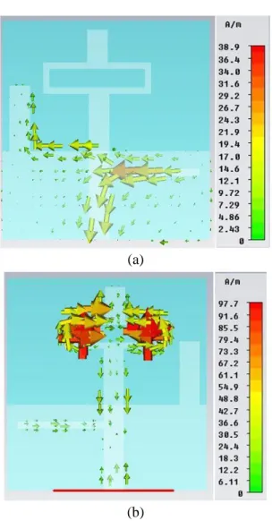
In order to elaborate on excited resonant modes of the proposed antenna, the simulated surface current distribution at resonant frequencies 2.4 GHz and 5.8 GHz are shown in Fig. 11.
(a)
(b)
Fig.11. Simulated surface current distribution at the resonant frequency (a) 2.45 GHz, and (b) 5.8 GHz
We can remark that at the resonance frequency 2.45GHz, a large surface current distribution is observed mainly on the stub in the ground plane and the stub tuning as shown in Fig. 11(a). This current distribution indicates that the first resonance mode is excited at 2.45GHz. This is due to the effective length of the surface current which has increased. Besides, the bandwidth of 2.45 GHz is principally controllable by the length of the stub in the ground plane as illustrated in Fig. 9. Furthermore, at the resonance frequency of
5.8GHz, a large surface current distribution is observed, mainly on the radiating patch as shown in Fig. 11(b). This distribution indicates that the resonance mode is excited at 5.8 GHz of this antenna because the effective length of the surface current is increased in view of radiating patch. In addition, the bandwidth of 5.8 GHz is principally controllable by the length of the radiating patch as depicted in Fig. 10.
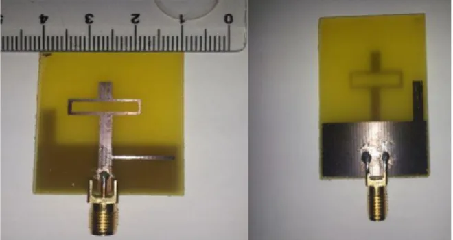
V. FABRICATION AND MEASUREMENT After completing the simulation step, the proposed antenna was fabricated on FR4 substrate. SMA connectors, soldered to the antenna edge, were used as a feeding port. The prototype of the proposed antenna is shown in Fig. 12.
Fig.12. Photograph of the fabricated prototypes of reader antenna
Fig. 13 shows the comparison between the simulated and measured results of the reflection coefficient of the reader antenna. The reflection coefficient was measured using the Anritsu Vector Network Analyzer. From the graph of Fig. 13, it can be seen that there is a good agreement between the measured and simulated results. With the measurement, the value of reflection coefficient of the first and the second resonance is -18.2 dB and -37.11 dB respectively.
Fig.13. Simulated and measured S11 versus frequency of the reader antenna
Table 3 gives the comparison between simulation and measurement of the proposed antenna. The measured level 𝑆11 is -18.2 dB and -37.11 dB for 2.45GHz and 5.8 GHz respectively. According to Table 3, it can be seen that the impedance matching has slightly decreased in the measurement. This might be due to the different environment parameters that are provided by the simulator software, or to some errors in the fabrication process. However, the measured bandwidth is higher than the simulated value in the second resonance (5.8GHz).
Table 3: Comparison between measurement and simulation results Measure Simulation Resonance frequency (GHz) 2.5 5.77 2.45 5.8 Bandwidth(MHz) 9 910 148.48 204.85 Level S11(dB) -18.2 -37.11 -30.1 -41.75
The following table sums up the advantages of the proposed antenna compared to other antennas proposed in the literature. It can be seen that the proposed antenna is significantly smaller, offers an important bandwidth and a good gain compared to its dimensions.
Table 4: Comparison between the proposed antenna and other research papers using the same FR4 substrate S11 (dB) Gain/Size (%) Size (mm2) 2.45GH z 5.8GHz 2.45GHz 5.8GHz Ref [6] 17.69 11.72 0.09 0.13 80 x 80 Ref [7] 30 22 0.12 0.2 50 x 50 Ref [10] 40 20.21 0.12 0.16 50 x 35 This work 30.1 41.75 0.21 0.376 30 x 30 VI. CONCLUSION
This paper presents a simple and low-cost dual band micro-strip antenna with two resonate paths. The first one, in the radiating element and the second in the protruding stub of the ground plane. The antenna comprises two resonances at 2.45GHz with an impedance bandwidth of 148.48MHz and at 5.8GHz with an impedance bandwidth of 204.85MHz. The proposed antenna has been studied, numerically analyzed, simulated using the CST and HFSS software, fabricated with FR4 substrate and measured using Anritsu VNA. It is compact in size, provides an appropriate gain, consistent radiation patterns, good impedance matching, and an excellent agreement between the simulated and measured results. These advantages qualify this antenna for dual-band operations in handheld RFID and WLAN applications.
REFERENCES
[1] K. Finkenzeller, “RFID Handbook” Wiley & Sons,
second edition, 2003
[2] H. Stockman “Communication by Means of
Reflected Power”, proceedings of the IRE, 36, pp 1196-1204, October 1948
[3] S. Nambi, S.Nyalamadugu, S.M. Wentworth and B.A Chin, “Radio Frequency Identification
Sensors” 7th World Multiconf. Systemic,
Cybernetics and Informatics, Orlando, FL.
pp.386-390, June 2003.
[4] Y.K. Jung and B. Lee “Dual-Band Circularly Polarized Microstrip RFID Reader Antenna Using
Metamaterial Branch-Line Coupler” IEEE
Transactions on Antennas and Propagation, Vol.
60, No. 2, pp.786-791, February 2012.
[5] A. T. Mobashsher, N. Misran, M. T. Islam “Design Analysis of Compact Dual-Band Microstrip RFID Reader Antenna”. International Conference on
Space Science and Communication, pp83-88,
October 26-27, 2009.
[6] J. Zhang, X.-M. Zhang, J.-S. Liu, Q.-F. Wu, T. Ying and H. Jin, “Dual-band Bidirectional High Gain Antenna for WLAN 2.4 and 5.8 GHz applications,” Electronics Letters, Vol. 45(1), pp. 6-7, January 1, 2009
[7] T. Lee, J. Jung, H. Lee, Y. Lim, “Modified annular ring slot antenna for dual WLAN band application." Microwave and Millimeter Wave
Technology, 2008. ICMMT 2008. International Conference on. Vol. 1. IEEE, pp. 410-412, April
21-24, 2008.
[8] N. Misran, M. T. Islam, N. M. Yusob and A. T. Mobashsher, “Design of a compact dual band microstrip antenna for ku-band application”
Electrical Engineering and Informatics, 2009. ICEEI'09. International Conference on. Vol. 2. IEEE, Aug 5-7, 2009.
[9] David M. Pozar Microwave Engineering, John
Wiley & Sons, Inc. Third Edition, 2005.
[10] Panda, Jyoti Ranjan, and Rakhesh Singh
Kshetrimayum. “A printed 2.4 GHz/5.8 GHz dual-band monopole antenna with a protruding stub in the ground plane for WLAN and RFID applications” Progress In Electromagnetics Research 117, pp. 425-434, June 16, 2011.
![Table 4: Comparison between the proposed antenna and other research papers using the same FR4 substrate S11 (dB) Gain/Size (%) Size (mm 2 ) 2.45GH z 5.8GHz 2.45GHz 5.8GHz Ref [6] 17.69 11.72 0.09 0.13 80 x 80 Ref [7] 30 22 0.12 0.2 50 x 50 Re](https://thumb-us.123doks.com/thumbv2/123dok_es/6886155.290498/8.918.108.441.270.439/table-comparison-proposed-antenna-research-papers-substrate-gain.webp)
