EVALUACIÓN FINAL
PRUEBA DE HABILIDADES PRÁCTICAS CISCO CCNP
HECTOR FABIO ACEVEDO ORTEGA
UNIVERSIDAD NACIONAL ABIERTA Y A DISTANCIA INGENIERÍA DE TELECOMUNICACIONES
DIPLOMADO CISCO CCNP PALMIRA
EVALUACIÓN PRUEBA DE HABILIDADES PRACTICAS CCNP
HECTOR FABIO ACEVEDO ORTEGA
Diplomado de profundización cisco CCNP prueba de Habilidades prácticas
Director:
MSc. Gerardo Granados Acuña
UNIVERSIDAD NACIONAL ABIERTA Y A DISTANCIA - UNAD INGENIERIA DE TELECOMUNICACIONES
DIPLOMADO CISCO CCNP PALMIRA
3
TABLA DE CONTENIDO
LISTA DE ILUSTRACIONES ... 4
LISTA DE TABLAS ... 5
GLOSARIO ... 6
RESUMEN ... 7
ABSTRACT ... 7
INTRODUCCIÓN ... 8
DESARROLLO DEL TRABAJO ... 9
1. Escenario 1 ... 9
1.1. Parte 1: Configuración del escenario propuesto ... 11
1.2. Parte 2: Verificar conectividad de red y control de la trayectoria. ... 18
2. Escenario 2 ... 21
2.1. Parte 1: Configurar la red de acuerdo con las especificaciones. ... 23
2.2. Parte 2: conectividad de red de prueba y las opciones configuradas. 35 CONCLUSIONES ... 45
BIBLIOGRAFÍA ... 46
4
LISTA DE ILUSTRACIONES
Ilustración 1. Escenario 1 ... 9
Ilustración 2. Diseño de escenario 1 en GNS3 ... 10
Ilustración 3. Tabla de enrutamiento de R1 – Bogotá ... 18
Ilustración 4. Tabla de enrutamiento de R2 – Bucaramanga ... 18
Ilustración 5. Tabla de enrutamiento de R3 – Medellín ... 19
Ilustración 6. Ping y traceroute R1 a R2 IPv4 ... 19
Ilustración 7. Ping y traceroute R1 a R2 IPv6 ... 19
Ilustración 8. Ping y traceroute R2 a R3 IPv4 ... 20
Ilustración 9. Ping y traceroute R2 a R3 IPv6 ... 20
Ilustración 10. Ping R1 a R3 IPv4 ... 20
Ilustración 11. Ping y traceroute R1 a R3 IPv6 ... 21
Ilustración 12. Verificando rutas filtradas en R1 ... 21
Ilustración 13. Escenario 2 ... 22
Ilustración 14. Diseño de escenario 2 en GNS3 ... 22
Ilustración 15. Verificando existencia de VLAN en DLS1 ... 36
Ilustración 16. Asignación de puertos troncales en DLS1 ... 36
Ilustración 17. Verificando el estado de todas las interfaces en DLS1 ... 37
Ilustración 18. Verificando existencia de VLAN en DLS2 ... 37
Ilustración 19. Asignación de puertos troncales en DLS2 ... 38
Ilustración 20. Verificando el estado de todas las interfaces en DLS2 ... 38
Ilustración 21. Verificando existencia de VLAN en ALS1 ... 39
Ilustración 22. Asignación de puertos troncales en ALS1 ... 39
Ilustración 23. Verificando el estado de todas las interfaces en ALS1 ... 40
Ilustración 24. Verificando existencia de VLAN en ALS2 ... 40
Ilustración 25. Asignación de puertos troncales en ALS2 ... 41
Ilustración 26. Verificando el estado de todas las interfaces en ALS2 ... 42
Ilustración 27. Verificando Ether-channel en DLS1 ... 42
Ilustración 28. Verificando Ether-channel en ALS1 ... 43
Ilustración 29. Verificando instancias en DLS1 ... 43
Ilustración 30. Verificando VLAN mapeadas en DLS1 ... 43
Ilustración 31. Verificando instancias en DLS2 ... 44
5
LISTA DE TABLAS
Tabla 1. Direccionamiento escenario 1 ... 10 Tabla 2. VLAN a configurar ... 28 Tabla 3. Asignamiento de interfaces a VLAN ... 34
6 GLOSARIO
CCNP: Cisco Certified Network Professional (CCNP) valida la capacidad de planificar, implementar, verificar y solucionar problemas de redes empresariales locales y de área amplia y trabajar en colaboración con especialistas en soluciones avanzadas de seguridad, voz, inalámbrica y video.
EIGRP: EIGRP se desarrolló como una versión mejorada del antiguo protocolo de enrutamiento de puerta de enlace interior (IGRP) y tiene muchas de las mismas características de un avanzado protocolo de puerta de enlace interior, como convergencia de alta velocidad, actualizaciones parciales y la posibilidad de admitir múltiples protocolos de capa de red.
EtherChannel: es una técnica que se usa cuando tienes múltiples conexiones al mismo dispositivo. En lugar de que cada enlace funcione de forma independiente, los canales de puertos se agrupan para trabajar como una sola unidad ayudando aumentar el ancho de banda.
GNS3: GNS3 es un simulador usado para emular, configurar, probar y solucionar problemas de redes virtuales y reales.
IOS: Internetwork Operating System, es el Sistema operativo que integran los dispositivos desarrollados por la empresa CISCO Networks como routers, switch, accesspoint, etc. Es un paquete específico para cada dispositivo que define sus funcionalidades y características.
LACP: es una versión estándar abierta de EtherChannel, LACP es compatible con la mayoría de los principales proveedores de equipos de red y proporciona interoperabilidad en entornos de múltiples proveedores.
OSPF: OSPF es un protocolo de enrutamiento de puerta de enlace interior que utiliza estados de enlace en lugar de distancia vectores para la selección de ruta. PAgP: es un protocolo propietario de Cisco aplicado a EtherChannel. Los paquetes son intercambiados entre switch a través de los enlaces configurados para ello.
VLAN: Red de Área Local Virtual, este método permite crear redes de área local independientes dentro de una misma red física, ayudan a reducir el dominio de difusión, facilitar la administración y seguridad.
7 RESUMEN
El diplomado de Cisco CCNP (Cisco Certified Networking Professional), está diseñado para permitir al profesional desarrollar la capacidad de planificar, implementar, verificar y solucionar problemas de redes empresariales locales y de área amplia y trabajar en colaboración con especialistas en soluciones avanzadas de seguridad, voz, redes inalámbricas y video. Consta de dos módulos CCNP router y CCNP switch que permiten abordar el núcleo problemico de gestión de sistemas y servicios de telecomunicaciones.
Se presenta a continuación el desarrollo de dos escenarios, uno para CCNP router y otro para CCNP switch, estos escenarios integraran gran parte del contenido realizado durante el diplomado. Se desarrolló utilizando el simulador GNS3 que permite emular IOS de cisco e integrar máquinas virtuales para integrar switch de capa 2 y capa 3.
Al final se mostrarán capturas de los resultados obtenidos después de haber desarrollado cada escenario, estos permiten verificar que todos los pasos se realizaron correctamente.
Palabras Clave: BGP, CCNP, EIGRP, Protocolos de Red, OSPF, Routing, Switching.
ABSTRACT
The Cisco CCNP (Cisco Certified Networking Professional), diplomat is designed to allow the professional to develop the ability to plan, implement, verify and solve problems of local and wide-area business networks and work in collaboration with specialists in advanced security solutions, Voice, wireless networks and video. It consists of two CCNP router and CCNP switch modules that allow addressing the problematic core of telecommunications systems and services management.
The development of two scenarios is presented below, one for CCNP router and one for CCNP switch, these scenarios will integrate much of the content made during the diplomat. It was developed using the GNS3 simulator that allows you to emulate Cisco IOS and integrate virtual machines to integrate Layer 2 and Layer 3 switches.
8
INTRODUCCIÓN
El presente informe hace referencia a la prueba de habilidades prácticas del diplomado Cisco CCNP. Se desarrollarán dos escenarios planteados para el módulo CCNP router y CCNP switch, que permitirán poner a prueba todos los conocimientos obtenidos a través del diplomado.
En el escenario 1 de CCNP router se pondrán a prueba habilidades como configuración de enrutamiento multi área con OSPF, configuración del protocolo EIGRP y redistribución entre ambos protocolos, así como todas las configuraciones básicas y avanzadas necesarias para lograr configurar exitosamente la topología de red.
En el escenario 2 de CCNP switch se pondrán a prueba habilidades con el planteamiento de una estructura Core de switch’s, que utilizan EtherChannel con la finalidad de brindar mayor velocidad en los enlaces troncales, hacer la red redundante y que esté preparada ante posibles fallos logrando evitar interrupciones en las conexiones, adicional de hacer uso de VLAN.
9
DESARROLLO DEL TRABAJO
1. Escenario 1
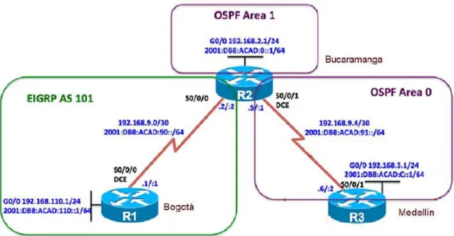
Una empresa de confecciones posee tres sucursales distribuidas en las ciudades de Bogotá, Medellín y Bucaramanga, en donde el estudiante será el administrador de la red, el cual deberá configurar e interconectar entre sí cada uno de los dispositivos que forman parte del escenario, acorde con los lineamientos establecidos para el direccionamiento IP, protocolos de enrutamiento y demás aspectos que forman parte de la topología de red.
Ilustración 1. Escenario 1
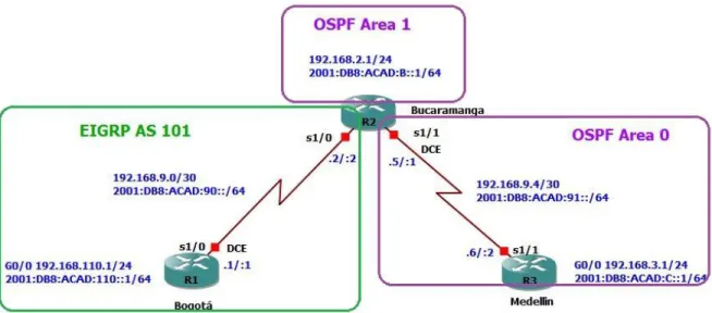
10 Ilustración 2. Diseño de escenario 1 en GNS3
Tabla 1. Direccionamiento escenario 1
Dis posi
tivo
Interfaz Dirección IPv4 / Máscara
Red Dirección IPv6 / Máscara
Red
R1 S1/0 192.168.9.1/30 192.168.9.0/30 2001:DB8:AC AD:90::1/64
2001:DB8: ACAD:90::/
64 G0/0 192.168.110.1/24 192.168.110.0/
24 2001:DB8:AC AD:110::1/64 2001:DB8: ACAD:110: :/64 R2 S1/0 192.168.9.2/30 192.168.9.0/30 2001:DB8:AC
AD:90::2/64
2001:DB8: ACAD:90::/
64 S1/1 192.168.9.5/30 192.168.9.4/30 2001:DB8:AC
AD:91::1/64
2001:DB8: ACAD:91::/
64 G0/0 192.168.2.1/24 192.168.2.0/24 2001:DB8:AC
AD:B::1/64
2001:DB8: ACAD:B::/
64 R3 S1/1 192.168.9.6/30 192.168.9.4/30 2001:DB8:AC
AD:91::2/64
2001:DB8: ACAD:91::/
64 G0/0 192.168.3.1/24 192.168.3.0/24 2001:DB8:AC
AD:C::1/64
2001:DB8: ACAD:C::/
11 Link-local Address de todas las interfaces:
R1 – FE80::1 R2 – FE80::2 R3 – FE80::3
Configurar la topología de red, de acuerdo con las siguientes especificaciones. 1.1. Parte 1: Configuración del escenario propuesto
1.1.1. Configurar las interfaces con las direcciones IPv4 e IPv6 que se muestran en la topología de red.
Solución:
Configuramos las interfaces de R1, R2 y R3 con las respectivas direcciones IPv4 e IPv6.
R1: R1#conf t
Enter configuration commands, one per line. End with CNTL/Z. R1(config)#hostname BOGOTA
BOGOTA(config)#no ip domain-lookup BOGOTA(config)#line con 0
BOGOTA(config-line)#logging synchronous BOGOTA(config-line)#exec-timeout 0 0 BOGOTA(config-line)#exit
BOGOTA(config)#int g0/0
BOGOTA(config-if)#ip address 192.168.110.1 255.255.255.0 BOGOTA(config-if)#ipv6 address FE80::1 link-local
BOGOTA(config-if)#ipv6 address 2001:DB8:ACAD:110::1/64 BOGOTA(config-if)#no shut
BOGOTA(config-if)#exit
BOGOTA#conf t
Enter configuration commands, one per line. End with CNTL/Z. BOGOTA(config)#int se1/0
BOGOTA(config-if)#ip address 192.168.9.1 255.255.255.252 BOGOTA(config-if)#ipv6 address FE80::1 link-local
BOGOTA(config-if)#ipv6 address 2001:DB8:ACAD:90::1/64 BOGOTA(config-if)#clock rate 64000
12 R2:
R2#conf t
Enter configuration commands, one per line. End with CNTL/Z. R2(config)#hostname BUCARAMANGA
BUCARAMANGA(config)#no ip domain-lookup BUCARAMANGA(config)#line con 0
BUCARAMANGA(config-line)#logging synchronous BUCARAMANGA(config-line)#exec-timeout 0 0 BUCARAMANGA(config-line)#exit
BUCARAMANGA(config)#int g0/0
BUCARAMANGA(config-if)#ip address 192.168.2.1 255.255.255.0 BUCARAMANGA(config-if)#ipv6 address FE80::2 link-local
BUCARAMANGA(config-if)#ipv6 address 2001:DB8:ACAD:B::1/64 BUCARAMANGA(config-if)#no shut
BUCARAMANGA(config-if)#exit
BUCARAMANGA#conf t
Enter configuration commands, one per line. End with CNTL/Z. BUCARAMANGA(config)#int se1/0
BUCARAMANGA(config-if)#ip address 192.168.9.2 255.255.255.252 BUCARAMANGA(config-if)#ipv6 address FE80::2 link-local
BUCARAMANGA(config-if)#ipv6 address 2001:DB8:ACAD:90::2/64 BUCARAMANGA(config-if)#no shut
BUCARAMANGA(config-if)#exit
BUCARAMANGA(config)#int se1/1
BUCARAMANGA(config-if)#ip address 192.168.9.5 255.255.255.252 BUCARAMANGA(config-if)#ipv6 address FE80::2 link-local
BUCARAMANGA(config-if)#ipv6 address 2001:DB8:ACAD:91::1/64 BUCARAMANGA(config-if)#clock rate 64000
BUCARAMANGA(config-if)#no shut BUCARAMANGA(config-if)#exit
R3:
R3#conf t
Enter configuration commands, one per line. End with CNTL/Z. R3(config)#hostname MEDELLIN
MEDELLIN(config)#no ip domain-lookup MEDELLIN(config)#line con 0
13 MEDELLIN(config)#int g0/0
MEDELLIN(config-if)#ip address 192.168.3.1 255.255.255.0 MEDELLIN(config-if)#ipv6 address FE80::3 link-local
MEDELLIN(config-if)#ipv6 address 2001:DB8:ACAD:C::1/64 MEDELLIN(config-if)#no shut
MEDELLIN(config-if)#exit
MEDELLIN(config)#int se1/1
MEDELLIN(config-if)#ip address 192.168.9.6 255.255.255.252 MEDELLIN(config-if)#ipv6 address FE80::3 link-local
MEDELLIN(config-if)#ipv6 address 2001:DB8:ACAD:91::2/64 MEDELLIN(config-if)#no shut
1.1.2. Ajustar el ancho de banda a 128 kbps sobre cada uno de los enlaces seriales ubicados en R1, R2, y R3 y ajustar la velocidad de reloj de las conexiones de DCE según sea apropiado.
Solución: BOGOTA(config)#int se1/0 BOGOTA(config-if)#bandwidth 128 BUCARAMANGA(config)#int s1/0 BUCARAMANGA(config-if)#bandwidth 128 BUCARAMANGA(config-if)#exit BUCARAMANGA(config)#int s1/1 BUCARAMANGA(config-if)#bandwidth 128 MEDELLIN(config)#int s1/1 MEDELLIN(config-if)#bandwidth 128
Nota: El reloj de las conexiones seriales se configuró ítem 1.
1.1.3. En R2 y R3 configurar las familias de direcciones OSPFv3 para IPv4 e IPv6. Utilice el identificador de enrutamiento 2.2.2.2 en R2 y 3.3.3.3 en R3 para ambas familias de direcciones.
Solución:
Configuración de las familias de direcciones IPv4 e IPv6 en R2: BUCARAMANGA#conf t
Enter configuration commands, one per line. End with CNTL/Z. BUCARAMANGA(config)#ipv6 unicast-routing
BUCARAMANGA(config)#router ospfv3 1
14
BUCARAMANGA(config-router-af)#router-id 2.2.2.2
BUCARAMANGA(config-router-af)#passive-interface gigabitethernet 0/0 BUCARAMANGA(config-router-af)#exit-address-family
BUCARAMANGA(config-router)#address-family ipv6 unicast BUCARAMANGA(config-router-af)#router-id 2.2.2.6
BUCARAMANGA(config-router-af)#passive-interface gigabitethernet 0/0 BUCARAMANGA(config-router-af)#exit-address-family
BUCARAMANGA(config-router)#exit
Configuración de las familias de direcciones IPv4 e IPv6 en R3: MEDELLIN(config)#ipv6 unicast-routing
MEDELLIN(config)#router ospfv3 1
MEDELLIN(config-router)#address-family ipv4 unicast MEDELLIN(config-router-af)#router-id 3.3.3.3
MEDELLIN(config-router-af)#passive-interface gigabitethernet 0/0 MEDELLIN(config-router-af)#exit-address-family
MEDELLIN(config-router)#address-family ipv6 unicast MEDELLIN(config-router-af)#router-id 3.3.3.6
MEDELLIN(config-router-af)#passive-interface gigabitethernet 0/0 MEDELLIN(config-router-af)#exit-address-family
MEDELLIN(config-router-af)#exit
1.1.4. En R2, configurar la interfaz G0/0 en el área 1 de OSPF y la conexión serial entre R2 y R3 en OSPF área 0.
Solución:
BUCARAMANGA(config)#int g0/0
BUCARAMANGA(config-if)#ospfv3 1 ipv4 area 1 BUCARAMANGA(config-if)#ospfv3 1 ipv6 area 1 BUCARAMANGA(config-if)#exit
BUCARAMANGA(config)#interface s1/1
BUCARAMANGA(config-if)#ospfv3 1 ipv4 area 0 BUCARAMANGA(config-if)#ospfv3 1 ipv6 area 0
1.1.5. En R3, configurar la interfaz G0/0 y la conexión serial entre R2 y R3 en OSPF área 0.
Solución:
MEDELLIN(config)#int g0/0
MEDELLIN(config-if)#ospfv3 1 ipv4 area 0 MEDELLIN(config-if)#ospfv3 1 ipv6 area 0 MEDELLIN(config-if)#exit
15 MEDELLIN(config-if)#ospfv3 1 ipv4 area 0 MEDELLIN(config-if)#
*Dec 3 21:17:09.367: %OSPFv3-5-ADJCHG: Process 1, IPv4, Nbr 2.2.2.2 on Serial1/1 from LOADING to FULL, Loading Done
MEDELLIN(config-if)#ospfv3 1 ipv6 area 0 MEDELLIN(config-if)#
*Dec 3 21:17:15.111: %OSPFv3-5-ADJCHG: Process 1, IPv6, Nbr 2.2.2.6 on Serial1/1 from LOADING to FULL, Loading Done
1.1.6. Configurar el área 1 como un área totalmente Stubby. Solución:
Configuramos un área totalmente Stubby para que no acepte sumarización, esto con el fin de que utilice una única ruta desde la troncal.
BUCARAMANGA(config)#router ospfv3 1
BUCARAMANGA(config-router)#address-family ipv4 unicast BUCARAMANGA(config-router-af)#area 1 stub no-summary BUCARAMANGA(config-router-af)#exit-address-family BUCARAMANGA(config-router)#address-family ipv6 unicast BUCARAMANGA(config-router-af)#area 1 stub no-summary
1.1.7. Propagar rutas por defecto de IPv4 y IPv6 en R3 al interior del dominio OSPFv3. Nota: Es importante tener en cuenta que una ruta por defecto es diferente a la definición de rutas estáticas.
Solución:
Propagación de rutas por defecto IPv4:
MEDELLIN(config)#ip route 0.0.0.0 0.0.0.0 192.168.9.5 MEDELLIN(config)#router ospf 1
MEDELLIN(config-router)#default-information originate
Propagación de rutas por defecto IPv6:
MEDELLIN(config)#ipv6 route ::/0 2001:db8:acad:91::1 MEDELLIN(config)#ipv6 router ospf 2
MEDELLIN(config-rtr)#default-information originate
16 Solución:
Configuración EIGRP en R1 - Bogotá: IPv4
BOGOTA(config)#router eigrp 1
BOGOTA(config-router)#no auto-summary
BOGOTA(config-router)# network 192.168.0.0 0.0.255.255
IPv6
BOGOTA(config)#ipv6 unicast-routing BOGOTA(config)#ipv6 router eigrp 1 BOGOTA(config-rtr)#eigrp router-id 1.1.1.1 BOGOTA(config-rtr)#no shut
BOGOTA(config-rtr)#exit BOGOTA(config)#int g0/0 BOGOTA(config-if)#ipv6 eigrp 1 BOGOTA(config-if)#exit
BOGOTA(config)#int s1/0 BOGOTA(config-if)#ipv6 eigrp 1
Configuración EIGRP en R2 - Bucaramanga: IPv4
BUCARAMANGA(config)#router eigrp 1
BUCARAMANGA(config-router)#no auto-summary
BUCARAMANGA(config-router)# network 192.168.0.0 0.0.255.255
IPv6
BUCARAMANGA(config)#ipv6 unicast-routing BUCARAMANGA(config)#ipv6 router eigrp 1 BUCARAMANGA(config-rtr)#eigrp router-id 2.2.2.2 BUCARAMANGA(config-rtr)#no shut
BUCARAMANGA(config-rtr)#exit BUCARAMANGA(config)#int s1/0 BUCARAMANGA(config-if)#ipv6 eigrp 1
1.1.9. Configurar las interfaces pasivas para EIGRP según sea apropiado. Solución:
BOGOTA(config)#router eigrp 1
17
1.1.10. En R2, configurar la redistribución mutua entre OSPF y EIGRP para IPv4 e IPv6. Asignar métricas apropiadas cuando sea necesario.
Solución:
Configuración de redistribución mutua entre OSPF y EIGRP para IPv4: BUCARAMANGA(config)#router ospf 1
BUCARAMANGA(config-router)#redistribute eigrp 1 subnets BUCARAMANGA(config-router)#exit
BUCARAMANGA(config)#router eigrp 1
BUCARAMANGA(config-router)#redistribute ospf 1 metric 10000 100 255 1 1500 BUCARAMANGA(config-router)#exit
BUCARAMANGA(config)#router eigrp 1
BUCARAMANGA(config-router)#default-metric 10000 100 255 1 1500 BUCARAMANGA(config-router)#redistribute ospf 1
Configuración de redistribución mutua entre OSPF y EIGRP para IPv6: BUCARAMANGA(config)#router ospfv3 1
BUCARAMANGA(config-router)#address-family ipv6 unicast
BUCARAMANGA(config-router-af)#redistribute eigrp 1 include-connected BUCARAMANGA(config-router-af)#exit
BUCARAMANGA(config-router)#exit
BUCARAMANGA(config)#ipv6 router eigrp 1
BUCARAMANGA(config-rtr)#$etric 1500 100 255 1 1500 include-connected BUCARAMANGA(config-rtr)#exit
1.1.11. En R2, deje de hacer publicidad de la ruta 192.168.3.0/24 a R1 mediante una lista de distribución y ACL.
Solución:
Teniendo en cuenta que R2 es quien redistribuye las rutas de R3 a R1 es a este router el que se le debe aplicar la lista de acceso.
BUCARAMANGA(config)#ip access-list standard OSPF20-FILTER
BUCARAMANGA(config-std-nacl)#remark Used with DList to filter OSPF 20 routes BUCARAMANGA(config-std-nacl)#deny 192.168.3.0 0.0.3.255
BUCARAMANGA(config-std-nacl)#permit any BUCARAMANGA(config-std-nacl)#exit
18
BUCARAMANGA(config-router)#distribute-list OSPF20-FILTER out ospf 1 BUCARAMANGA(config-router)#exit
1.2. Parte 2: Verificar conectividad de red y control de la trayectoria. 1.2.1. Registrar las tablas de enrutamiento en cada uno de los routers, acorde
con los parámetros de configuración establecidos en el escenario propuesto.
Solución:
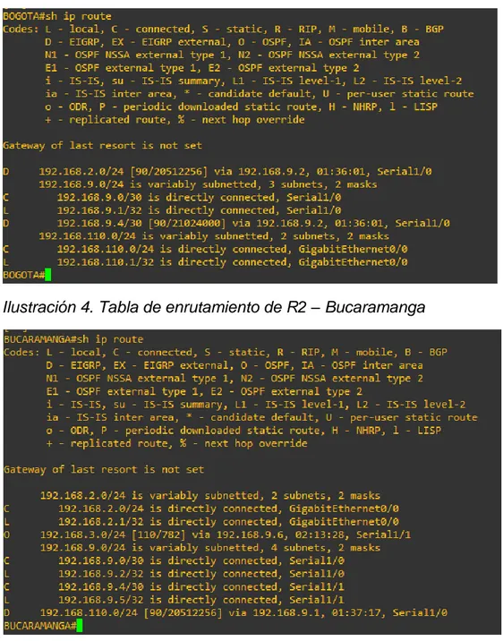
Ilustración 3. Tabla de enrutamiento de R1 – Bogotá
19
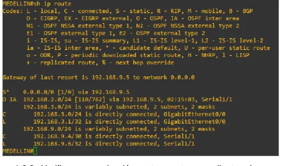
Ilustración 5. Tabla de enrutamiento de R3 – Medellín
1.2.2. Verificar comunicación entre routers mediante el comando ping y traceroute.
Solución:
Prueba comunicación R1 a R2:
Ilustración 6. Ping y traceroute R1 a R2 IPv4
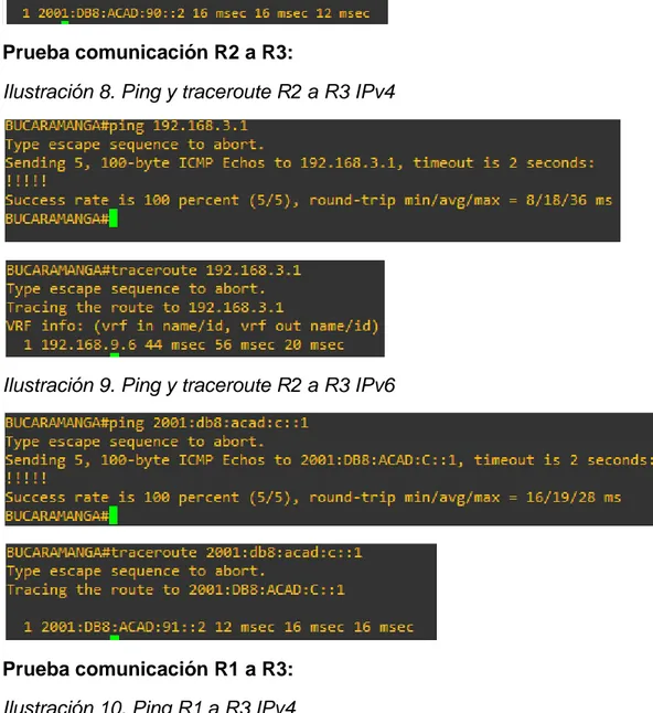
20 Prueba comunicación R2 a R3:
Ilustración 8. Ping y traceroute R2 a R3 IPv4
Ilustración 9. Ping y traceroute R2 a R3 IPv6
Prueba comunicación R1 a R3: Ilustración 10. Ping R1 a R3 IPv4
21 Ilustración 11. Ping y traceroute R1 a R3 IPv6
1.2.3. Verificar que las rutas filtradas no están presentes en las tablas de enrutamiento de los routers correctas.
Solución:
Ilustración 12. Verificando rutas filtradas en R1
Efectivamente comprobamos que dentro de la tabla de enrutamiento de R1 no existe ninguna ruta hacia R3, específicamente hacia la red 192.168.3.0 y también comprobamos que en R3 tampoco existe la ruta hacia la red local de R1 192.168.110.0.
2. Escenario 2
22 Ilustración 13. Escenario 2
Para la puesta en práctica del escenario 2 se hace uso del simulador GNS3 en sistema operativo Windows 7 64 Bits, usando dos switch de capa 3 con IOS adventerprisek9-15.2c.bin y dos switch LanBase con IOS i86bi-linux-l2-ipbasek9-15.1g.bin, por tal motivo las interfaces cambian en cuanto a su numeración, a continuación, se muestra topología realizada en GNS3:
23
2.1. Parte 1: Configurar la red de acuerdo con las especificaciones. 2.1.1. Apagar todas las interfaces en cada switch.
Solución: DLS1: DLS1#conf t
DLS1(config)#int range e0/0-3 DLS1(config-if-range)#shut DLS1(config-if-range)#exit DLS1(config)#int range e1/0-1 DLS1(config-if-range)#shut DLS1(config-if-range)#exit DLS1(config)#int e3/3 DLS1(config-if)#shut DLS2: DLS2#conf t
DLS2(config)#int range e0/0-3 DLS2(config-if-range)#shut DLS2(config-if-range)#exit DLS2(config)#int range e1/0-1 DLS2(config-if-range)#shut DLS2(config-if-range)#exit DLS2(config)#int e3/3 DLS2(config-if)#shut ALS1: ALS1#conf t
ALS1(config)#int range e0/0-3 ALS1(config-if-range)#shut ALS1(config-if-range)#exit ALS1(config)#int e3/3 ALS1(config-if)#shut ALS2: ALS2#conf t
24
2.1.2. Asignar un nombre a cada switch acorde al escenario establecido. Solución:
DLS1: DLS1#conf t
Enter configuration commands, one per line. End with CNTL/Z. DLS1(config)#hostname DLS1
DLS2: DLS2#conf t
Enter configuration commands, one per line. End with CNTL/Z. DLS2(config)#hostname DLS2
ALS1: ALS1#conf t
Enter configuration commands, one per line. End with CNTL/Z. ALS1(config)#hostname ALS1
ALS2: ALS2#conf t
Enter configuration commands, one per line. End with CNTL/Z. ALS2(config)#hostname ALS2
2.1.3. Configurar los puertos troncales y Port-channels tal como se muestra en el diagrama.
a. La conexión entre DLS1 y DLS2 será un EtherChannel capa-3 utilizando LACP. Para DLS1 se utilizará la dirección IP 10.12.12.1/30 y para DLS2 utilizará 10.12.12.2/30.
b. Los Port-channels en las interfaces e0/0 y e0/1 utilizarán LACP. c. Los Port-channels en las interfaces e0/2 y e0/3 utilizará PAgP. d. Todos los puertos troncales serán asignados a la VLAN 800 como la
VLAN nativa. Solución:
Configuramos una Vlan de administración para DLS1 y DLS2: DLS1(config)#interface vlan 99
25 DLS2(config)#interface vlan 99
DLS2(config-if)#ip address 10.12.12.2 255.255.255.252 DLS2(config-if)#no shut
Configuramos los puertos troncales: DLS1:
DLS1(config)#interface range e0/0-3
DLS1(config-if-range)#switchport trunk encapsulation dot1q DLS1(config-if-range)#switchport trunk native vlan 800 DLS1(config-if-range)#switchport mode trunk
DLS1(config-if-range)#switchport nonegotiate DLS1(config-if-range)#no shut
DLS1(config-if-range)# switchport trunk allowed vlan except 1,999 DLS1(config-if-range)#exit
DLS1(config)#interface range e1/0-1
DLS1(config-if-range)#switchport trunk encapsulation dot1q DLS1(config-if-range)#switchport trunk native vlan 800 DLS1(config-if-range)#switchport mode trunk
DLS1(config-if-range)#switchport nonegotiate DLS1(config-if-range)#no shut
DLS1(config-if-range)# switchport trunk allowed vlan except 1,999 DLS2:
DLS2(config)#interface range e0/0-3
DLS2(config-if-range)#switchport trunk encapsulation dot1q DLS2(config-if-range)#switchport trunk native vlan 800 DLS2(config-if-range)#switchport mode trunk
DLS2(config-if-range)#switchport nonegotiate DLS2(config-if-range)#no shut
DLS2(config-if-range)# switchport trunk allowed vlan except 1,999 DLS2(config-if-range)#exit
DLS2(config)#interface range e1/0-1
DLS2(config-if-range)#switchport trunk encapsulation dot1q DLS2(config-if-range)#switchport trunk native vlan 800 DLS2(config-if-range)#switchport mode trunk
DLS2(config-if-range)#switchport nonegotiate DLS2(config-if-range)#no shut
DLS2(config-if-range)# switchport trunk allowed vlan except 1,999
ALS1:
ALS1(config)#interface range e0/0-3
26
ALS1(config-if-range)#switchport trunk native vlan 800 ALS1(config-if-range)#switchport mode trunk
ALS1(config-if-range)#no shut
ALS1(config-if-range)# switchport trunk allowed vlan except 1,999 ALS1(config-if-range)#exit
ALS2:
ALS2(config)#interface range e0/0-3
ALS2(config-if-range)#switchport trunk encapsulation dot1q ALS2(config-if-range)#switchport trunk native vlan 800 ALS2(config-if-range)#switchport mode trunk
ALS2(config-if-range)#no shut
ALS2(config-if-range)# switchport trunk allowed vlan except 1,999 ALS2(config-if-range)#exit
Configuramos la conexión entre DLS1 y DLS2 para usar EtherChannel con LACP:
El primer paso es desactivar las interfaces en ambos switch para que Misconfig Guard no las coloque en estado error disabled.
DLS1:
DLS1(config)# interface range E1/0-1 DLS1(config-if-range)# shutdown
DLS1(config-if-range)# channel-group 2 mode active DLS1(config-if-range)# no shutdown
DLS2:
DLS2(config)# interface range E1/0-1 DLS2(config-if-range)# shutdown
DLS2(config-if-range)# channel-group 2 mode active DLS2(config-if-range)# no shutdown
Configuramos Port-channel para la conexión entre DLS1 y ALS1 con LACP: DLS1:
DLS1(config)# interface range E0/0-1 DLS1(config-if-range)# shutdown
27 ALS1:
ALS1(config)# interface range E0/0-1 ALS1(config-if-range)# shutdown
ALS1(config-if-range)# channel-group 1 mode active ALS1(config-if-range)# no shutdown
Configuramos Port-channel para la conexión entre DLS1 y ALS1 con LACP:
DLS2:
DLS2(config)# interface range E0/0-1 DLS2(config-if-range)# shutdown
DLS2(config-if-range)# channel-group 3 mode active DLS2(config-if-range)# no shutdown
ALS2:
ALS2(config)# interface range E0/0-1 ALS2(config-if-range)# shutdown
ALS2(config-if-range)# channel-group 3 mode active ALS2(config-if-range)# no shutdown
Configuramos Port-channel para la conexión entre DLS1 y ALS2 con PAgP: DLS1:
DLS1(config)# interface range E0/2-3 DLS1(config-if-range)# shutdown
DLS1(config-if-range)# channel-group 4 mode desirable DLS1(config-if-range)# no shutdown
ALS2:
ALS2(config)# interface range E0/2-3 ALS2(config-if-range)# shutdown
ALS2(config-if-range)# channel-group 4 mode desirable ALS2(config-if-range)# no shutdown
Configuramos Port-channel para la conexión entre DLS2 y ALS1 con PAgP: DLS2:
28
DLS2(config-if-range)# channel-group 5 mode desirable DLS2(config-if-range)# no shutdown
ALS1:
ALS1(config)# interface range E0/2-3 ALS1(config-if-range)# shutdown
ALS1(config-if-range)# channel-group 5 mode desirable ALS1(config-if-range)# no shutdown
2.1.4. Configurar DLS1, ALS1, y ALS2 para utilizar VTP versión 3. a. Utilizar el nombre de dominio UNAD con la contraseña cisco123 b. Configurar DLS1 como servidor principal para las VLAN.
c. Configurar ALS1 y ALS2 como clientes VTP. Solución:
DLS1:
DLS1(config)# vtp domain UNAD DLS1(config)# vtp version 3 DLS1(config)# vtp mode server
DLS1(config)# vtp password cisco123 ALS1:
ALS1(config)# vtp domain UNAD ALS1(config)# vtp version 3 ALS1(config)# vtp mode client
ALS1(config)# vtp password cisco123 ALS1(config)# end
ALS2:
ALS2(config)# vtp domain UNAD ALS2(config)# vtp version 3 ALS2(config)# vtp mode client
ALS2(config)# vtp password cisco123 ALS2(config)# end
29 Solución:
DLS1(config)# vlan 99
DLS1(config-vlan)# name MANAGMENT DLS1(config-vlan)# vlan 800
DLS1(config-vlan)# name NATIVA DLS1(config-vlan)# vlan 12
DLS1(config-vlan)# name EJECUTIVOS DLS1(config-vlan)# vlan 234
DLS1(config-vlan)# name HUESPEDES DLS1(config-vlan)# vlan 1111
DLS1(config-vlan)# name VIDEONET DLS1(config-vlan)# vlan 434
DLS1(config-vlan)# name ESTACIONAMIENTO DLS1(config-vlan)# vlan 123
DLS1(config-vlan)# name MANTENIMIENTO DLS1(config-vlan)# vlan 1010
DLS1(config-vlan)# name VOZ DLS1(config-vlan)# vlan 3456
DLS1(config-vlan)# name ADMINISTRACION DLS1(config-vlan)# exit
2.1.6. En DLS1, suspender la VLAN 434. Solución:
DLS1(config-vlan)# vlan 434 DLS1(config-vlan)# state suspend
2.1.7. Configurar DLS2 en modo VTP transparente VTP utilizando VTP versión 2, y configurar en DLS2 las mismas VLAN que en DLS1.
Solución:
Habilitamos VTP v2 en modo transparente en DLS2: DLS2#conf t
30 DLS2(config)#vtp version 2
DLS2(config)#vtp mode transparent
Setting device to VTP Transparent mode for VLANS. DLS2(config)#
Configuramos todas las vlan en DLS2:
DLS2(config)# vlan 99
DLS2(config-vlan)# name MANAGMENT DLS2(config-vlan)# vlan 800
DLS2(config-vlan)# name NATIVA DLS2(config-vlan)# vlan 12
DLS2(config-vlan)# name EJECUTIVOS DLS2(config-vlan)# vlan 234
DLS2(config-vlan)# name HUESPEDES DLS2(config-vlan)# vlan 1111
DLS2(config-vlan)# name VIDEONET DLS2(config-vlan)# vlan 434
DLS2(config-vlan)# name ESTACIONAMIENTO DLS2(config-vlan)# vlan 123
DLS2(config-vlan)# name MANTENIMIENTO DLS2(config-vlan)# vlan 1010
DLS2(config-vlan)# name VOZ DLS2(config-vlan)# vlan 3456
DLS2(config-vlan)# name ADMINISTRACION DLS2(config-vlan)# exit
2.1.8. Suspender VLAN 434 en DLS2. Solución:
DLS2(config-vlan)# vlan 434 DLS2(config-vlan)# state suspend
2.1.9. En DLS2, crear VLAN 567 con el nombre de CONTABILIDAD. La VLAN de CONTABILIDAD no podrá estar disponible en cualquier otro Switch de la red.
Solución:
En este punto creamos en DLS2 una Vlan que será privada, es decir que solo estará disponible para el switch DLS2 y creara una restricción de la comunicación de la capa 2 para las interfaces configuradas con esta Vlan.
31 DLS2(config-vlan)# private-vlan primary DLS2(config-vlan)# name CONTABILIDAD DLS2(config-vlan)# exit
2.1.10. Configurar DLS1 como Spanning tree root para las VLAN 1, 12, 434, 800, 1010, 1111 y 3456 y como raíz secundaria para las VLAN 123 y 234.
Solución:
Para configurar en DLS1 VLANs en modo root (primario) o secundarias, es necesario configurar MST (árbol de expansión múltiple) y propagarlo dentro de VTP para que los demás Switches que estén en el dominio UNAD reciban las actualizaciones y todo el árbol de expansión.
Implementamos MST: DLS1#conf t
Enter configuration commands, one per line. End with CNTL/Z. DLS1(config)# spanning-tree mode mst
DLS1(config)#exit
DLS1# clear spanning-tree detected-protocols
Con ayuda de VTP v3 propagamos mst:
DLS1# conf t
DLS1(config)# vtp mode server mst DLS1(config)# end
DLS1# vtp primary mst
Agregamos las dos instancias para los dos grupos de VLAN, primaria y secundaria:
Root primaria DLS1# conf t
Enter configuration commands, one per line. End with CNTL/Z. DLS1(config)# spanning-tree mst config
DLS1(config-mst)# instance 2 vlan 1, 12, 434, 800, 1010, 1111,3456
Root secundaria DLS1# conf t
Enter configuration commands, one per line. End with CNTL/Z. DLS1(config)# spanning-tree mst config
32
Definimos root primario y root secundario en DLS1:
DLS1# conf t
Enter configuration commands, one per line. End with CNTL/Z. DLS1(config)# spanning-tree mst 0-2 root primary
DLS1(config)# spanning-tree mst 3 root secondary DLS1(config)# end
2.1.11. Configurar DLS2 como Spanning tree root para las VLAN 123 y 234 y como una raíz secundaria para las VLAN 12, 434, 800, 1010, 1111 y 3456.
Solución:
Implementamos MST: DLS2#conf t
Enter configuration commands, one per line. End with CNTL/Z. DLS2(config)# spanning-tree mode mst
DLS2(config)#exit
DLS2# clear spanning-tree detected-protocols DLS2# conf t
DLS2(config)# vtp mode server mst
Root primaria
DLS2# conf t
Enter configuration commands, one per line. End with CNTL/Z. DLS2(config)# spanning-tree mst config
DLS2(config-mst)# instance 1 vlan 123, 234
Root secundaria DLS2# conf t
Enter configuration commands, one per line. End with CNTL/Z. DLS2(config)# spanning-tree mst config
DLS2(config-mst)# instance 2 vlan 12, 434, 800, 1010, 1111,3456
Definimos root primario y root secundario en DLS2:
DLS2# conf t
Enter configuration commands, one per line. End with CNTL/Z. DLS2(config)# spanning-tree mst 0-1 root primary
33
2.1.12. Configurar todos los puertos como troncales de tal forma que
solamente las VLAN que se han creado se les permitirá circular a través de éstos puertos.
Solución:
Configuramos los demás puertos de los cuatro switches en modo troncal para permitir el paso en cada uno de las VLAN.
DLS1:
DLS1(config)#interface range e1/2-3, e2/0-3, e3/0-3
DLS1(config-if-range)#switchport trunk encapsulation dot1q DLS1(config-if-range)#switchport trunk native vlan 800 DLS1(config-if-range)#switchport mode trunk
DLS1(config-if-range)#switchport nonegotiate DLS1(config-if-range)#no shut
DLS1(config-if-range)# switchport trunk allowed vlan except 1,999 DLS1(config-if-range)#exit
DLS2:
DLS2(config)#interface range e1/2-3, e2/0-3, e3/0-3
DLS2(config-if-range)#switchport trunk encapsulation dot1q DLS2(config-if-range)#switchport trunk native vlan 800 DLS2(config-if-range)#switchport mode trunk
DLS2(config-if-range)#switchport nonegotiate DLS2(config-if-range)#no shut
DLS2(config-if-range)# switchport trunk allowed vlan except 1,999 DLS2(config-if-range)#exit
ALS1:
ALS1(config)#interface range e1/0-3, e2/0-3, e3/0-3
ALS1(config-if-range)#switchport trunk encapsulation dot1q ALS1(config-if-range)#switchport trunk native vlan 800 ALS1(config-if-range)#switchport mode trunk
ALS1(config-if-range)#no shut
ALS1(config-if-range)# switchport trunk allowed vlan except 1,999 ALS1(config-if-range)#exit
ALS2:
ALS2(config)#interface range e1/0-3, e2/0-3, e3/0-3
34
ALS2(config-if-range)#switchport trunk native vlan 800 ALS2(config-if-range)#switchport mode trunk
ALS2(config-if-range)#no shut
ALS2(config-if-range)# switchport trunk allowed vlan except 1,999 ALS2(config-if-range)#exit
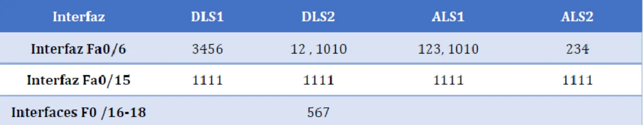
2.1.13. Configurar las siguientes interfaces como puertos de acceso, asignados a las VLAN de la siguiente manera:
Tabla 3. Asignamiento de interfaces a VLAN
Solución: DLS1: DLS1#conf t
Enter configuration commands, one per line. End with CNTL/Z. DLS1(config)#int e3/3
DLS1(config-if)#switchport mode access DLS1(config-if)#switchport access vlan 3456 DLS1(config-if)#exit
DLS1(config)#int e2/1
DLS1(config-if)#switchport mode access DLS1(config-if)#switchport access vlan 1111 DLS1(config-if)#exit
DLS2: DLS2#conf t
Enter configuration commands, one per line. End with CNTL/Z. DLS2(config)#int e3/3
DLS2(config-if)#switchport mode access DLS2(config-if)#switchport access vlan 12 DLS2(config-if)#switchport access vlan 1010 DLS2(config-if)#exit
35 DLS2(config-if)#switchport mode access DLS2(config-if)#switchport access vlan 1111 DLS2(config-if)#exit
DLS2(config)#int range e2/2-3, e3/0-3 DLS2(config-if)#switchport mode access DLS2(config-if)#switchport access vlan 567 DLS2(config-if)#exit
ALS1: ALS1#conf t
Enter configuration commands, one per line. End with CNTL/Z. ALS1(config)#int e3/3
ALS1(config-if)#switchport mode access ALS1(config-if)#switchport access vlan 123 ALS1(config-if)#switchport access vlan 1010 ALS1(config-if)#exit
ALS1(config)#int e2/1
ALS1(config-if)#switchport mode access ALS1(config-if)#switchport access vlan 1111 ALS1(config-if)#exit
ALS2: ALS2#conf t
Enter configuration commands, one per line. End with CNTL/Z. ALS2(config)#int e3/3
ALS2(config-if)#switchport mode access ALS2(config-if)#switchport access vlan 234 ALS2(config-if)#exit
ALS2(config)#int e2/1
ALS2(config-if)#switchport mode access ALS2(config-if)#switchport access vlan 1111 ALS2(config-if)#exit
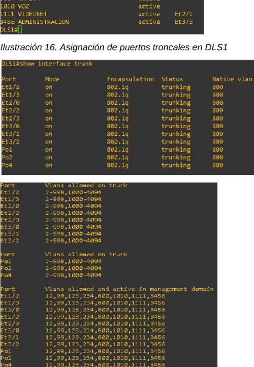
2.2. Parte 2: conectividad de red de prueba y las opciones configuradas. 2.2.1. Verificar la existencia de las VLAN correctas en todos los switches y la
36 DLS1:
Ilustración 15. Verificando existencia de VLAN en DLS1
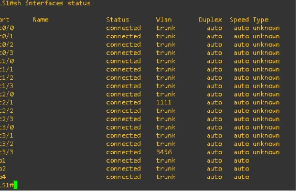
37
Ilustración 17. Verificando el estado de todas las interfaces en DLS1
DLS2:
38
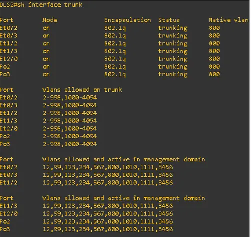
Ilustración 19. Asignación de puertos troncales en DLS2
39 ALS1:
Ilustración 21. Verificando existencia de VLAN en ALS1
40
Ilustración 23. Verificando el estado de todas las interfaces en ALS1
ALS2:
41
42
Ilustración 26. Verificando el estado de todas las interfaces en ALS2
2.2.2. Verificar que el EtherChannel entre DLS1 y ALS1 está configurado correctamente.
Solución: DLS1
DLS1#show etherchannel summary
Ilustración 27. Verificando Ether-channel en DLS1
Nota: El EtherChannel entre DLS1 y ALS1 está identificado como Po1 utilizando LACP.
43 ALS1#show EtherChannel summary
Ilustración 28. Verificando Ether-channel en ALS1
2.2.3. Verificar la configuración de Spanning tree entre DLS1 o DLS2 para cada VLAN.
Solución: DLS1:
Ilustración 29. Verificando instancias en DLS1
44 DLS2:
Ilustración 31. Verificando instancias en DLS2
45
CONCLUSIONES
Con el desarrollo de la prueba de habilidades prácticas CCNP, se logró obtener capacidades para administrar dispositivos de red como routers y switches, mediante el estudio de la arquitectura TCP/IP y el uso de recursos y herramientas necesarias para establecer conectividad de red y solucionar los inconvenientes presentados.
Se fortalecieron los fundamentos básicos para la implementación de plataformas de red escalables mediante el uso del modelo jerárquico de tres niveles, para mejorar el rendimiento de la red e incorporar eficientemente los protocolos de conmutación mejorados como: VLAN, VTP, RSTP, PVSTP y el encapsulamiento mediante 802.1q.
46
BIBLIOGRAFÍA
Froom, R., Frahim, E. (2015). CISCO Press (Ed). InterVLAN Routing. Implementing Cisco IP Switched Networks (SWITCH) Foundation Learning Guide CCNP SWITCH 300-115. Recuperado de https://1drv.ms/b/s!AmIJYei-NT1IlnWR0hoMxgBNv1CJ
Froom, R., Frahim, E. (2015). CISCO Press (Ed). Spanning Tree Implementation. Implementing Cisco IP Switched Networks (SWITCH) Foundation Learning Guide CCNP SWITCH 300-115. Recuperado de https://1drv.ms/b/s!AmIJYei-NT1IlnWR0hoMxgBNv1CJ
Froom, R., Frahim, E. (2015). CISCO Press (Ed). Switch Fundamentals Review. Implementing Cisco IP Switched Networks (SWITCH) Foundation Learning Guide CCNP SWITCH 300-115. Recuperado de https://1drv.ms/b/s!AmIJYei-NT1IlnWR0hoMxgBNv1CJ
Teare, D., Vachon B., Graziani, R. (2015). CISCO Press (Ed). Basic Network and Routing Concepts. Implementing Cisco IP Routing (ROUTE) Foundation Learning Guide CCNP ROUTE 300-101. Recuperado de https://1drv.ms/b/s!AmIJYei-NT1IlnMfy2rhPZHwEoWx
Teare, D., Vachon B., Graziani, R. (2015). CISCO Press (Ed). EIGRP Implementation. Implementing Cisco IP Routing (ROUTE) Foundation Learning Guide CCNP ROUTE 300-101. Recuperado de https://1drv.ms/b/s!AmIJYei-NT1IlnMfy2rhPZHwEoWx