EVALUACIÓN FINAL
PRUEBA DE HABILIDADES PRÁCTICAS CISCO CCNP
LUZ ADRIANA YÉPEZ RAMOS.
UNIVERSIDAD NACIONAL ABIERTA Y A DISTANCIA INGENIERÍA DE TELECOMUNICACIONES
DIPLOMADO CISCO CCNP MEDELLIN
EVALUACIÓN PRUEBA DE HABILIDADES PRACTICAS CCNP
LUZ ADRIANA YÉPEZ RAMOS
Diplomado de profundización cisco CCNP prueba de Habilidades prácticas
Director(a):
Gerardo Granados Acuña
Magíster en Telemática e Ingeniero de Sistemas
UNIVERSIDAD NACIONAL ABIERTA Y A DISTANCIA - UNAD INGENIERIA DE TELECOMUNICACIONES
DIPLOMADO CISCO CCNP MEDELLIN
3
NOTA DE ACEPTACIÓN:
Presidente del Jurado
Jurado
Jurado
4
AGRADECIMIENTOS
Los resultados de este proyecto están dedicados a todas aquellas personas que, de alguna forma, contribuyeron en su consolidación. Los más sinceros agradecimientos están dirigidos hacia el director del diplomado cisco CCNP, Gerardo Granados Acuña, quien con su ayuda brindó información relevante, precisa y de calidad para resolver todas las inquietudes presentadas durante de la ejecución de este proyecto. A los compañeros de estudio, que contribuyeron a la construcción de continuo conocimiento. A la familia por siempre brindar su apoyo incondicional y emocional y principalmente los agradecimientos están dirigidos a todos los instructores que aportaron en la construcción de continuo conocimiento y que sin el cual no hubiese podido salir adelante.
Gracias Dios, gracias hermanos, gracias familiares y en especial, gracias madre.
5
TABLA DE CONTENIDO
LISTA DE ILUSTRACIONES ... 6
LISTA DE TABLAS ... 8
GLOSARIO ... 9
RESUMEN ... 11
ABSTRACT ... 12
INTRODUCCIÓN ... 13
ESCENARIO 1. ... 14
Parte 1: Configuración del escenario propuesto. ... 15
Parte 2: Configuración del escenario propuesto. ... 26
ESCENARIO 2. ... 34
Parte 1: Configuración del escenario propuesto. ... 34
Parte 2: Conectividad de red de prueba y las opciones configuradas. ... 48
CONCLUSIONES ... 57
6
LISTA DE ILUSTRACIONES
Ilustración 1. Escenario 1. ... 14
Ilustración 2. Escenario 1. ... 15
Ilustración 3. Tabla de enrutamiento router Bogotá. ... 26
Ilustración 4. Tabla de enrutamiento router Bucaramanga. ... 26
Ilustración 5. Tabla de enrutamiento router Medellín. ... 27
Ilustración 6. Prueba de conectividad con PING hacia la LAN del enrutador de Bucaramanga. ... 27
Ilustración 7. Prueba de conectividad con PING hacia interfaz serial del enrutador de Bucaramanga. ... 27
Ilustración 8. Prueba de conectividad con PING hacia LAN del enrutador de Medellín. ... 28
Ilustración 9. Prueba de conectividad con PING hacia interfaz serial del enrutador de Medellín. ... 28
Ilustración 10. Prueba de conectividad con TRACEROUTE hacia la LAN del enrutador de Bucaramanga. ... 28
Ilustración 11. Prueba de conectividad con TRACEROUTE hacia interfaz serial del enrutador de Bucaramanga. ... 28
Ilustración 12. Prueba de conectividad con TRACEROUTE hacia LAN del enrutador de Medellín. ... 29
Ilustración 13. Prueba de conectividad con TRACEROUTE hacia interfaz serial del enrutador de Medellín. ... 29
Ilustración 14. Prueba de conectividad con PING hacia LAN del enrutador de Bogotá. ... 29
Ilustración 15. Prueba de conectividad con PING hacia LAN del enrutador de Medellín. ... 29
Ilustración 16. Prueba de conectividad con TRACEROUTE hacia LAN del enrutador de Bogotá. ... 30
Ilustración 17. Prueba de conectividad con TRACEROUTE hacia LAN del enrutador de Medellín. ... 30
Ilustración 18. Prueba de conectividad con PING hacia la LAN del enrutador de Bucaramanga. ... 30
Ilustración 19. Prueba de conectividad con PING hacia interfaz serial del enrutador de Bucaramanga. ... 30
Ilustración 20. Prueba de conectividad con PING hacia la LAN del enrutador de Bogotá. ... 31
7
Ilustración 22. Prueba de conectividad con TRACEROUTE hacia LAN del
enrutador de Bucaramanga. ... 31 Ilustración 23. Prueba de conectividad con TRACEROUTE hacia interfaz serial del enrutador de Bucaramanga. ... 31 Ilustración 24. Prueba de conectividad con TRACEROUTE hacia LAN del
enrutador de Bogotá. ... 32 Ilustración 25. Prueba de conectividad con TRACEROUTE hacia interfaz serial del enrutador de Bogotá. ... 32 Ilustración 26. Verificación de rutas filtradas en la tabla de enrutamiento en el router de Bogotá... 32 Ilustración 27. Verificación de rutas filtradas en la tabla de enrutamiento en el router de Bogotá... 34 Ilustración 28. Verificación de VLAN en el switch de distribución DLS1. ... 48 Ilustración 29. Verificación de interfaces troncales en el switch de distribución DLS1... 49 Ilustración 30. Verificación de VLAN en el switch de acceso ALS1. ... 49
Ilustración 31. Verificación de interfaces troncales en el switch de acceso ALS1. 50
Ilustración 32. Verificación de VLAN en el switch de distribución DLS2. ... 50 Ilustración 33. Verificación de interfaces troncales en el switch de distribución DLS1... 51 Ilustración 34. Verificación de VLAN en el switch de acceso ALS2... 51
Ilustración 35. Verificación de interfaces troncales en el switch de acceso ALS2. 52
Ilustración 36. Verificación de interfaces etherchannel en el switch de distribución DLS1... 52 Ilustración 37. Verificación de interfaces etherchannel en el switch de acceso ALS1. ... 53 Ilustración 38. Verificación de spanning-tree bridge para instancia de VLAN creada en switch de distribución DLS1. ... 53 Ilustración 39. Verificación de spanning-tree summary para el switch de
distribución DLS1. ... 54 Ilustración 40. Verificación de spanning-tree root para instancia de VLAN creada en switch de distribución DLS1. ... 54 Ilustración 41. Verificación de spanning-tree bridge para instancia de VLAN
creada en switch de distribución DLS2. ... 55 Ilustración 42. Verificación de spanning-tree summary para el switch de
8
LISTA DE TABLAS
9 GLOSARIO
CCNP: es una certificación de nivel medio ofrecida por Cisco Systems para los candidatos que desean desarrollar su carrera en el campo de las redes. La certificación consiste en aprobar 3 exámenes, a saber, CCNP Route, CCNP Switch y CCNP TShoot. Esta certificación permite validar la capacidad de planificar, implementar, verificar y solucionar problemas de redes empresariales locales y de área amplia y trabajar en colaboración con especialistas en soluciones avanzadas de seguridad, voz, inalámbrica y video.
Gns3: es un software de código abierto que simula redes complejas mientras está lo más cerca posible del rendimiento de las redes reales. Todo esto sin tener hardware de red dedicado, como enrutadores y conmutadores.
Este software proporciona una interfaz gráfica de usuario intuitiva para diseñar y configurar redes virtuales, se ejecuta en hardware de PC tradicional y puede usarse en múltiples sistemas operativos, incluidos Windows, Linux y MacOS X.
Networking: también conocida como redes de computadoras, es la práctica de transportar e intercambiar datos entre dispositivos a través de un medio compartido en un sistema de información. La creación de redes comprende no solo el diseño, construcción y uso de una red, sino también la gestión, mantenimiento y operación de la infraestructura de red, software y políticas.
Protocolos de red: son estándares y políticas formales formados por reglas, procedimientos y formatos que definen la comunicación entre dos o más dispositivos a través de una red. Éstos conducen la acción, las políticas y los asuntos del proceso integral de datos o comunicaciones de red seguras, administradas y oportunas. Definen reglas y convenciones para la comunicación. Incorporan todos los requisitos de proceso y las limitaciones de iniciar y lograr la comunicación entre computadoras, enrutadores, servidores y otros dispositivos habilitados para la red.
10
11 RESUMEN
En este trabajo se desarrolla la prueba de habilidades prácticas del diplomado de profundización Cisco CCNP, el cual permite evidenciar las habilidades y competencias adquiridas en tecnologías de conmutación y enrutamiento a lo largo del diplomado.
Las actividades desarrolladas para cada objetivo propuesto por el diplomado de profundización CCNP, se relacionan de la siguiente forma: el primer escenario, se basa en la implementación de una empresa de confecciones que posee 3 sucursales, de la cual se deben apropiar dichas tecnologías avanzadas de enrutamiento para lograr la comunicación exitosa entre ellas. En las configuraciones realizadas, se hace uso de los dominios de enrutamiento OSPFv3 y EIGRP Named, protocolos enrutados como IPv4 e IPv6, mecanismos de redistribución y filtrado de rutas, entre otras cosas conceptos cómo áreas OSPF y la implementación de address-family para el soporte de instancia virtuales de enrutamiento en el dominio de enrutamiento EIGRP.
En el segundo escenario, una empresa de comunicaciones presenta un diseño de red basado en bloques de distribución y acceso donde se deben apropiar tecnologías avanzadas de conmutación para lograr la comunicación entre redes LAN virtuales. En las configuraciones realizadas, se hace uso tecnologías de capa 2 como VLAN, VTPv3, EtherChannel con protocolos de agregación como LACP/PAgP y spanning-tree.
12 ABSTRACT
In this work the practical skills test of the Cisco CCNP deepening diploma is developed, which allows to demonstrate the skills and competences acquired in switching and routing technologies throughout the diploma.
The activities developed for each objective proposed by the CCNP deepening diploma are related as follows: the first scenario is based on the implementation of a clothing company that has 3 branches, from which these advanced technologies of routing to achieve successful communication between them. In the configurations made, use of the routing domains OSPFv3 and EIGRP Named, routed protocols such as IPv4 and IPv6, mechanisms for redistribution and filtering of routes, among other things concepts such as OSPF areas and the implementation of address family for the support of virtual routing instance in the EIGRP routing domain.
In the second scenario, a communications company presents a network design based on distribution and access blocks where advanced switching technologies must be appropriated to achieve communication between virtual LAN networks. In the configurations made, layer 2 technologies such as VLAN, VTPv3, EtherChannel with aggregation protocols such as LACP / PAgP and spanning-tree are used.
13
INTRODUCCIÓN
Las redes actualmente están teniendo cambios radicales y los ingenieros deben estar preparados para la implementación y soporte de nuevas tecnologías. Servicios como redes definidas en software en el acceso, en la WAN y en el datacenter exigen una preparación continua del profesional en redes y para lograrlo, debe contar con una fundamentación técnica en conceptos y protocolos bastante sólida en tecnologías de conmutación y enrutamiento. El diplomado de profundización de Cisco CCNP, brinda una completa descripción de los conceptos de redes de nivel empresarial, cómo también, da un amplio alcance de cómo implementarlas y resolver sus problemas. Además, se ofrece un estudio avanzado de tecnologías de enrutamiento y conmutación para redes empresariales de datos, voz y video convergentes.
14 Desarrollo del trabajo
ESCENARIO 1.
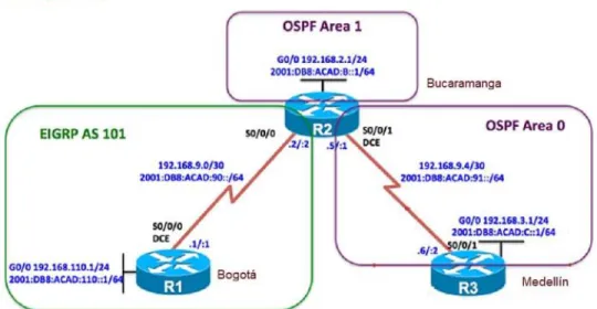
Una empresa de confecciones posee tres sucursales distribuidas en las ciudades de Bogotá, Medellín y Bucaramanga, en donde el estudiante será el administrador de la red, el cual deberá configurar e interconectar entre sí cada uno de los dispositivos que forman parte del escenario, acorde con los lineamientos establecidos para el direccionamiento IP, protocolos de enrutamiento y demás aspectos que forman parte de la topología de red.
Ilustración 1. Escenario 1.
15
Ilustración 2. Escenario 1.
Fuente 2 (creado por: Luz Adriana Yépez).
Parte 1: Configuración del escenario propuesto.
1. Configurar las interfaces con las direcciones IPv4 e IPv6 que se muestran en la
topología de red.
RESPUESTA: a continuación, se muestran las configuraciones iniciales de los 3 enrutadores del escenario 1, nombrados cada uno con su respetivo nombre según el ejercicio:
ROUTER BOGOTA.
Router> enable
Router# configure terminal
Router(config)# hostname Bogota
16
Bogota(config-if)# ip address 192.168.9.1 255.255.255.252
Bogota(config-if)# ipv6 address 2001:db8:acad:90::1/64 Bogota(config-if)# no shutdown
Bogota(config-if)# interface GigabitEthernet 0/0 Bogota(config-if)# description LAN R1
Bogota(config-if)# ip address 192.168.110.1 255.255.255.0
Bogota(config-if)# ipv6 address 2001:db8:acad:110::1/64 Bogota(config-if)# no shutdown
ROUTER BUCARAMANGA.
Router> enable
Router# configure terminal
Router(config)# hostname Bucaramanga
Bucaramanga(config)# ipv6 unicast-routing Bucaramanga(config)# interface Serial 1/0 Bucaramanga(config-if)# description TO R1
Bucaramanga(config-if)# ip address 192.168.9.2 255.255.255.252 Bucaramanga(config-if)# ipv6 address 2001:db8:acad:90::2/64 Bucaramanga(config-if)# no shutdown
Bucaramanga(config-if)# interface Serial 1/1 Bucaramanga(config-if)# description TO R3 Bucaramanga(config-if)# clock rate 56000
Bucaramanga(config-if)# ip address 192.168.9.5 255.255.255.252 Bucaramanga(config-if)# ipv6 address 2001:db8:acad:91::1/64 Bucaramanga(config-if)# no shutdown
17 Bucaramanga(config-if)# description LAN R2
Bucaramanga(config-if)# ip address 192.168.2.1 255.255.255.0 Bucaramanga(config-if)# ipv6 address 2001:db8:acad:b::1/64
Bucaramanga(config-if)# no shutdown
ROUTER MEDELLIN.
Router> enable
Router# configure terminal
Router(config)# hostname Medellin Medellin(config)# ipv6 unicast-routing
Medellin(config-if)# interface Serial 1/1 Medellin(config-if)# description TO R2
Medellin(config-if)# ip address 192.168.9.6 255.255.255.252
Medellin(config-if)# ipv6 address 2001:db8:acad:91::2/64 Medellin(config-if)# no shutdown
Medellin(config-if)# interface GigabitEthernet 0/0
Medellin(config-if)# description LAN R1
Medellin(config-if)# ip address 192.168.3.1 255.255.255.0 Medellin(config-if)# ipv6 address 2001:db8:acad:c::1/64
Medellin(config-if)# no shutdown
2. Ajustar el ancho de banda a 128 kbps sobre cada uno de los enlaces seriales
ubicados en R1, R2 y R3 y ajustar la velocidad de reloj de las conexiones de DCE según sea apropiado.
18 ROUTER BOGOTA.
Bogota(config-if)# interface Serial 1/0
Bogota(config-if)# clock rate 56000 Bogota(config-if)# bandwidth 128
ROUTER BUCARAMANGA.
Bucaramanga(config-if)# interface Serial 1/0
Bucaramanga(config-if)# bandwidth 128 Bucaramanga(config-if)# interface Serial 1/1
Bucaramanga(config-if)# clock rate 56000 Bucaramanga(config-if)# bandwidth 128
ROUTER MEDELLIN.
Medellin(config-if)# interface Serial 1/1
Medellin(config-if)# bandwidth 128
3. En R2 y R3 configurar las familias de direcciones OSPFv3 para IPv4 e IPv6. Utilice el identificador de enrutamiento 2.2.2.2 en R2 y 3.3.3.3 en R3 para ambas familias de direcciones.
19 ROUTER BUCARAMANGA.
Bucaramanga(config-if)# interface Serial 1/1
Bucaramanga(config-if)# ospfv3 1 ipv6 area 0 Bucaramanga(config-if)# ospfv3 1 ipv4 area 0 Bucaramanga(config-if)# router ospfv3 1
Bucaramanga(config-router)# router-id 2.2.2.2
ROUTER MEDELLIN.
Medellin(config-if)# interface Serial 1/1
Medellin(config-if)# ospfv3 1 ipv6 area 0 Medellin(config-if)# ospfv3 1 ipv4 area 0 Medellin(config-if)# router ospfv3 1
Medellin(config-router)# router-id 3.3.3.3
4. En R2, configurar la interfaz F0/0 en el área 1 de OSPF y la conexión serial entre
R2 y R3 en OSPF área 0.
RESPUESTA: a continuación, se muestran las configuraciones de áreas sobre el protocolo de enrutamiento OSPFv3 para el enrutador de la ciudad de Bucaramanga.
ROUTER BUCARAMANGA.
Bucaramanga(config-if)# interface GigabitEthernet0/0 Bucaramanga(config-if)# ospfv3 1 ipv6 area 1
20 Bucaramanga(config-if)# ospfv3 1 ipv6 area 0
Bucaramanga(config-if)# ospfv3 1 ipv4 area 0
5. En R3, configurar la interfaz F0/0 y la conexión serial entre R2 y R3 en OSPF
área 0.
RESPUESTA: a continuación, se muestran las configuraciones de áreas sobre el protocolo de enrutamiento OSPFv3 para el enrutador de la ciudad de Medellín.
ROUTER MEDELLIN.
Medellin(config-if)# interface GigabitEthernet0/0 Medellin(config-if)# ospfv3 1 ipv6 area 0
Medellin(config-if)# ospfv3 1 ipv4 area 0
Medellin(config-if)# interface Serial 1/1 Medellin(config-if)# ospfv3 1 ipv6 area 0 Medellin(config-if)# ospfv3 1 ipv4 area 0
6. Configurar el área 1 como un área totalmente Stubby.
RESPUESTA: a continuación, se muestran las configuraciones de área totally stubby sobre el protocolo de enrutamiento OSPFv3 para el enrutador de la ciudad de Bucaramanga, la cual permite anunciar la ruta default con LSA tipo 3.
ROUTER BUCARAMANGA.
Bucaramanga(config-if)# router ospfv3 1
21
7. Propagar rutas por defecto de IPv4 y IPv6 en R3 al interior del dominio OSPFv3.
Nota: Es importante tener en cuenta que una ruta por defecto es diferente a la definición de rutas estáticas.
RESPUESTA: a continuación, se muestran las configuraciones de propagación de la ruta por defecto desde el enrutador de la ciudad de Medellín, el cual le permitirá enseñar en el dominio OSPF la ruta de último recurso.
ROUTER MEDELLIN.
Medellin(config-if)# router ospfv3 1
Medellin(config-router)# address-family ipv4 unicast
Medellin(config-router)# default-information originate always Medellin(config-router)# exit-address-family
Medellin(config-router)# address-family ipv6 unicast
Medellin(config-router)# default-information originate always Medellin(config-router)# exit-address-family
8. Realizar la configuración del protocolo EIGRP para IPv4 como IPv6. Configurar
la interfaz F0/0 de R1 y la conexión entre R1 y R2 para EIGRP con el sistema autónomo 101. Asegúrese de que el resumen automático está desactivado.
RESPUESTA: a continuación, se muestran las configuraciones del protocolo de enrutamiento EIGRP named para IPv4 e IPV6 el cual permite tener sobre una instancia virtual los 2 protocolos ip funcionando con el sistema autónomo 101.
ROUTER BOGOTA.
Bogota(config-if)# router eigrp DUAL
22
Bogota(config-router-af)# network 192.168.9.0 0.0.0.3
Bogota(config-router-af)# address-family ipv6 unicast autonomous-system 101
ROUTER BUCARAMANGA.
Bucaramanga(config-if)# router eigrp DUAL
Bucaramanga(config-router)# address-family ipv4 unicast autonomous-system 101 Bucaramanga(config-router-af)# network 192.168.2.0 0.0.0.255
Bucaramanga(config-router-af)# network 192.168.9.0 0.0.0.3
Bucaramanga(config-router-af)# address-family ipv6 unicast autonomous-system 101
9. Configurar las interfaces pasivas para EIGRP según sea apropiado.
RESPUESTA: a continuación, se muestran las configuraciones de interfaces pasivas sobre la instancia de enrutamiento virtual de eigrp named DUAL, la cual evita la participación de vecinos indeseados sobre el protocolo de enrutamiento.
ROUTER BOGOTA.
Bogota(config-if)# router eigrp DUAL
Bogota(config-router)# address-family ipv4 unicast autonomous-system 101 Bogota(config-router-af)# af-interface GigabitEthernet0/0
Bogota(config-router-af-interface)# passive-interface Bogota(config-router-af-interface)# exit-af-interface
Bogota(config-router-af)# address-family ipv6 unicast autonomous-system 101
23
Bogota(config-router-af-interface)# exit-af-interface
ROUTER BUCARAMANGA.
Bucaramanga(config-if)# router eigrp DUAL
Bucaramanga(config-router)# address-family ipv4 unicast autonomous-system 101
Bucaramanga(config-router-af)# af-interface GigabitEthernet0/0 Bucaramanga(config-router-af-interface)# passive-interface Bucaramanga(config-router-af-interface)# af-interface Serial1/1
Bucaramanga(config-router-af-interface)# exit-af-interface
Bucaramanga(config-router-af)# address-family ipv6 unicast autonomous-system 101
Bucaramanga(config-router-af-interface)# af-interface GigabitEthernet0/0 Bucaramanga(config-router-af-interface)# passive-interface
Bucaramanga(config-router-af-interface)# af-interface Serial1/1
Bucaramanga(config-router-af-interface)# exit-af-interface
10. En R2, configurar la redistribución mutua entre OSPF y EIGRP para IPv4 e IPv6.
Asignar métricas apropiadas cuando sea necesario.
RESPUESTA: a continuación, se muestran las configuraciones de redistribución de rutas para los protocolos ip en los dominios OSPF y EIGRP con el fin de que exista completo conocimiento de las rutas en todos los enrutadores de la red.
ROUTER BUCARAMANGA.
Bucaramanga(config-if)# router eigrp DUAL
24
Bucaramanga(config-router-af-topology)# redistribute ospfv3 1 metric 1000 10 255 1 1500
Bucaramanga(config-router-af-topology)# exit-af-topology
Bucaramanga(config-router-af)# address-family ipv6 unicast autonomous-system 101
Bucaramanga(config-router-af)# topology base
Bucaramanga(config-router-af-topology)# redistribute ospf 1 metric 1000 10 255 1 1500
Bucaramanga(config-router-af-topology)# exit-af-topology
Bucaramanga(config-router)# router ospfv3 1
Bucaramanga(config-router)# address-family ipv4 unicast Bucaramanga(config-router-af)# redistribute eigrp 101 Bucaramanga(config-router-af)# exit-address-family
Bucaramanga(config-router)# address-family ipv6 unicast Bucaramanga(config-router-af)# redistribute eigrp 101
11. En R2, de hacer publicidad de la ruta 192.168.3.0/24 a R1 mediante una lista
de distribución y ACL.
RESPUESTA: a continuación, se muestran las configuraciones de una lista de distribución que permitirá el filtrado del prefijo de red 192.168.3.0/24 en el dominio de enrutamiento EIGRP 101.
ROUTER BUCARAMANGA.
Bucaramanga(config) ip access-list standard FILTRO_EIGRP Bucaramanga(config-std-nacl)# deny 192.168.3.0 0.0.0.255 Bucaramanga(config-std-nacl)# permit any
25
Bucaramanga(config-router)# address-family ipv4 unicast autonomous-system 101
Bucaramanga(config-router-af)# topology base
Bucaramanga(config-router-af-topology)# distribute-list FILTRO_EIGRP out
26
Parte 2: Configuración del escenario propuesto.
a. Registrar las tablas de enrutamiento en cada uno de los routers, acorde con
los parámetros de configuración establecidos en el escenario propuesto.
ROUTER BOGOTA.
Ilustración 3. Tabla de enrutamiento router Bogotá.
Fuente 3 (creado por: Luz Adriana Yépez).
ROUTER BUCARAMANGA.
Ilustración 4. Tabla de enrutamiento router Bucaramanga.
27 ROUTER MEDELLIN.
Ilustración 5. Tabla de enrutamiento router Medellín.
Fuente 5 (creado por: Luz Adriana Yépez).
b. Verificar comunicación entre routers mediante el comando ping y traceroute.
Ilustración 6. Prueba de conectividad con PING hacia la LAN del enrutador de Bucaramanga.
Fuente 6 (creado por: Luz Adriana Yépez).
Ilustración 7. Prueba de conectividad con PING hacia interfaz serial del enrutador de Bucaramanga.
28
Ilustración 8. Prueba de conectividad con PING hacia LAN del enrutador de Medellín.
Fuente 8 (creado por: Luz Adriana Yépez).
Ilustración 9. Prueba de conectividad con PING hacia interfaz serial del enrutador de Medellín.
Fuente 9 (creado por: Luz Adriana Yépez).
Ilustración 10. Prueba de conectividad con TRACEROUTE hacia la LAN del enrutador de Bucaramanga.
Fuente 10 (creado por: Luz Adriana Yépez).
Ilustración 11. Prueba de conectividad con TRACEROUTE hacia interfaz serial del enrutador de Bucaramanga.
29
Ilustración 12. Prueba de conectividad con TRACEROUTE hacia LAN del enrutador de Medellín.
Fuente 12 (creado por: Luz Adriana Yépez).
Ilustración 13. Prueba de conectividad con TRACEROUTE hacia interfaz serial del enrutador de Medellín.
Fuente 13 (creado por: Luz Adriana Yépez).
Ilustración 14. Prueba de conectividad con PING hacia LAN del enrutador de Bogotá.
Fuente 14 (creado por: Luz Adriana Yépez).
Ilustración 15. Prueba de conectividad con PING hacia LAN del enrutador de Medellín.
30
Ilustración 16. Prueba de conectividad con TRACEROUTE hacia LAN del enrutador de Bogotá.
Fuente 16 (creado por: Luz Adriana Yépez).
Ilustración 17. Prueba de conectividad con TRACEROUTE hacia LAN del enrutador de Medellín.
Fuente 17 (creado por: Luz Adriana Yépez).
Ilustración 18. Prueba de conectividad con PING hacia la LAN del enrutador de Bucaramanga.
Fuente 18 (creado por: Luz Adriana Yépez).
Ilustración 19. Prueba de conectividad con PING hacia interfaz serial del enrutador de Bucaramanga.
31
Ilustración 20. Prueba de conectividad con PING hacia la LAN del enrutador de Bogotá.
Fuente 20 (creado por: Luz Adriana Yépez).
Ilustración 21. Prueba de conectividad con PING hacia interfaz serial del enrutador de Bogotá.
Fuente 21 (creado por: Luz Adriana Yépez).
Ilustración 22. Prueba de conectividad con TRACEROUTE hacia LAN del enrutador de Bucaramanga.
Fuente 22 (creado por: Luz Adriana Yépez).
Ilustración 23. Prueba de conectividad con TRACEROUTE hacia interfaz serial del enrutador de Bucaramanga.
32
Ilustración 24. Prueba de conectividad con TRACEROUTE hacia LAN del enrutador de Bogotá.
Fuente 24 (creado por: Luz Adriana Yépez).
Ilustración 25. Prueba de conectividad con TRACEROUTE hacia interfaz serial del enrutador de Bogotá.
Fuente 25 (creado por: Luz Adriana Yépez).
c. Verificar que las rutas filtradas no están presentes en las tablas de enrutamiento de los routers correctas.
Ilustración 26. Verificación de rutas filtradas en la tabla de enrutamiento en el router de Bogotá.
33
34
ESCENARIO 2.
Una empresa de comunicaciones presenta una estructura Core acorde a la topología de red, en donde el estudiante será el administrador de la red, el cual deberá configurar e interconectar entre sí cada uno de los dispositivos que forman parte del escenario, acorde con los lineamientos establecidos para el direccionamiento IP, etherchannels, VLANs y demás aspectos que forman parte del escenario propuesto.
Ilustración 27. Verificación de rutas filtradas en la tabla de enrutamiento en el router de Bogotá.
Fuente 27 (Universidad Nacional Abierta y a Distancia).
Parte 1: Configuración del escenario propuesto.
a. Apagar todas las interfaces en cada switch.
35 Switch> enable
Switch# configure terminal
Switch(config)# interface range FastEthernet 0/1-24
Switch(config)# shutdown
b. Asignar un nombre a cada switch acorde al escenario establecido.
RESPUESTA: a continuación, se muestran cómo se asignan los hostname a cada uno de los switches de la topología de red.
Switch> enable
Switch# configure terminal Switch(config)# hostname ALS1
Switch> enable
Switch# configure terminal
Switch(config)# hostname ALS2
Switch> enable
Switch# configure terminal Switch(config)# hostname DLS1
Switch> enable
Switch# configure terminal
Switch(config)# hostname DLS2
c. Configurar los puertos troncales y Port-channels tal como se muestra en el
36
1) La conexión entre DLS1 y DLS2 será un EtherChannel capa-3
utilizando LACP. Para DLS1 se utilizará la dirección IP 10.12.12.1/30 y para DLS2 utilizará 10.12.12.2/30.
RESPUESTA: a continuación, se muestran cómo se configuran 2 port-channel de capa 3 en modo LACP para los switches de distribución DLS1 y DLS2.
DLS1(config)# interface range FastEthernet 0/11-12 DLS1(config-if-range)# no switchport
DLS1(config-if-range)# channel-group 12 mode active
DLS1(config-if-range)# no shutdown
DLS1(config-if-range)# interface port-channel 12
DLS1(config-if-range)# ip address 10.12.12.1 255.255.255.252
DLS2(config)# interface range FastEthernet 0/11-12 DLS2(config-if-range)# no switchport
DLS2(config-if-range)# channel-group 12 mode active DLS2(config-if-range)# no shutdown
DLS2(config-if-range)# interface port-channel 12
DLS2(config-if-range)# ip address 10.12.12.2 255.255.255.252
2) Los Port-channels en las interfaces Fa0/7 y Fa0/8 utilizarán LACP.
RESPUESTA: a continuación, se muestran cómo se configuran un etherchannel en capa 2 en modo LACP desde los switches de distribución DLS1 y ALS1 y DLS2 y ALS2.
37
DLS1(config-if-range)# channel-group 1 mode active
DLS1(config-if-range)# no shutdown
ALS1(config)# interface range FastEthernet 0/7-8 ALS1(config-if-range)# channel-group 1 mode active ALS1(config-if-range)# no shutdown
DLS2(config-if-range)# interface range FastEthernet 0/7-8 DLS2(config-if-range)# channel-group 2 mode active
DLS2(config-if-range)# no shutdown
ALS2(config)# interface range FastEthernet 0/7-8 ALS2(config-if-range)# channel-group 2 mode active ALS2(config-if-range)# no shutdown
3) Los Port-channels en las interfaces F0/9 y fa0/10 utilizará PAgP.
RESPUESTA: a continuación, se muestran cómo se configuran un etherchannel en capa 2 en modo PAgP desde los switches de distribución DLS1 y ALS2 y DLS2 y ALS1.
DLS1(config-if-range)# interface range FastEthernet 0/9-10 DLS1(config-if-range)# channel-group 4 mode desirable DLS1(config-if-range)# no shutdown
ALS2(config-if-range)# interface range FastEthernet 0/9-10
38
DLS2(config-if-range)# interface range FastEthernet 0/9-10 DLS2(config-if-range)# channel-group 3 mode desirable
DLS2(config-if-range)# no shutdown
ALS1(config-if-range)# interface range FastEthernet 0/9-10
ALS1(config-if-range)# channel-group 3 mode desirable ALS1(config-if-range)# no shutdown
4) Todos los puertos troncales serán asignados a la VLAN 800 como la
VLAN nativa.
RESPUESTA: a continuación, se muestran como los puertos troncales son configurados en modo troncal con la vlan nativa 800 en sus configuraciones.
DLS1(config)# vlan 800
DLS1(config-vlan)# name VLAN_NATIVA DLS1(config-vlan)# interface Port-Channel1
DLS1(config-if)# switchport trunk encapsulation dot1q DLS1(config-if)# switchport mode trunk
DLS1(config-if)# switchport trunk native vlan 800
DLS1(config-if)# interface Port-Channel4
DLS1(config-if)# switchport trunk encapsulation dot1q DLS1(config-if)# switchport mode trunk
DLS1(config-if)# switchport trunk native vlan 800
ALS1(config)# vlan 800
39 ALS1(config-vlan)# interface Port-Channel1
ALS1(config-if)# switchport trunk encapsulation dot1q ALS1(config-if)# switchport mode trunk
ALS1(config-if)# switchport trunk native vlan 800 ALS1(config-if)# interface Port-Channel3
ALS1(config-if)# switchport trunk encapsulation dot1q
ALS1(config-if)# switchport mode trunk
ALS1(config-if)# switchport trunk native vlan 800
DLS2(config)# vlan 800
DLS2(config-vlan)# name VLAN_NATIVA
DLS2(config-vlan)# interface Port-Channel2
DLS2(config-if)# switchport trunk encapsulation dot1q DLS2(config-if)# switchport mode trunk
DLS2(config-if)# switchport trunk native vlan 800 DLS2(config-if)# interface Port-Channel3
DLS2(config-if)# switchport trunk encapsulation dot1q
DLS2(config-if)# switchport mode trunk
DLS2(config-if)# switchport trunk native vlan 800
ALS2(config)# vlan 800
ALS2(config-vlan)# name VLAN_NATIVA ALS2(config-vlan)# interface Port-Channel2
ALS2(config-if)# switchport trunk encapsulation dot1q ALS2(config-if)# switchport mode trunk
ALS2(config-if)# switchport trunk native vlan 800
40
ALS2(config-if)# switchport trunk encapsulation dot1q
ALS2(config-if)# switchport mode trunk
ALS2(config-if)# switchport trunk native vlan 800
d. Configurar DLS1, ALS1, y ALS2 para utilizar VTP versión 3.
1) Utilizar el nombre de dominio UNAD con la contraseña cisco123.
RESPUESTA: a continuación, se muestra como se configuración VTP en cada uno de los switches topología.
DLS1(config)# vtp domain UNAD
DLS1(config)# vtp password cisco123 DLS1(config)# vtp version 3
ALS1(config)# vtp domain UNAD ALS1(config)# vtp password cisco123
ALS1(config)# vtp version 3
DLS2(config)# vtp domain UNAD
DLS2(config)# vtp password cisco123 DLS2(config)# vtp version 3
41
2) Configurar DLS1 como servidor principal para las VLAN.
RESPUESTA: a continuación, se muestra cómo se configuración VTP en cada uno de los switches topología.
DLS1> enable
DLS1# vtp primary
3) Configurar ALS1 y ALS2 como clientes VTP.
RESPUESTA: a continuación, se muestra cómo se configuran los switches ALS1 y ALS2 en modo vtp client.
ALS1# configure terminal ALS1(config)# vtp mode client
ALS2# configure terminal ALS2(config)# vtp mode client
e. Configurar en el servidor principal las siguientes VLAN:
Tabla 1. Configuración de VLAN.
Número
de VLAN Nombre de VLAN
Número de
VLAN Nombre de VLAN
800 NATIVA 434 ESTACIONAMIENTO
12 EJECUTIVOS 123 MANTENIMIENTO
234 HUESPEDES 1010 VOZ
1111 VIDEONET 3456 ADMINISTRACIÓN
42
RESPUESTA: a continuación, se muestra cómo se realiza la configuración de VLAN en el switch de distribución DLS1.
DLS1> enable
DLS1# configure terminal
DLS1(config)# vlan 12
DLS1(config-vlan)# name EJECUTIVOS DLS1(config-vlan)# vlan 234
DLS1(config-vlan)# name HUESPEDES DLS1(config-vlan)# vlan 1111
DLS1(config-vlan)# name VIDEONET
DLS1(config-vlan)# vlan 434
DLS1(config-vlan)# name ESTACIONAMIENTO DLS1(config-vlan)# vlan 123
DLS1(config-vlan)# name MANTENIMIENTO DLS1(config-vlan)# vlan 1010
DLS1(config-vlan)# name VOZ
DLS1(config-vlan)# vlan 3456
DLS1(config-vlan)# name ADMINISTRACION
f. En DLS1, suspender la VLAN 434.
RESPUESTA: a continuación, se suspende la VLAN 434 en el switch de distribución DLS1 el cual es el VTP primary del protocolo troncal de VLAN.
DLS1(config)# vlan 434
43
g. Configurar DLS2 en modo VTP transparente VTP utilizando VTP versión 2, y
configurar en DLS2 las mismas VLAN que en DLS1.
RESPUESTA: a continuación, se realiza la configuración de VTP en modo transparente y en versión 2 con las respectivas vlans.
DLS2(config)# vtp mode transparent DLS2(config)# vtp version 2
DLS2(config-vlan)# vlan 12
DLS2(config-vlan)# name EJECUTIVOS DLS2(config-vlan)# vlan 234
DLS2(config-vlan)# name HUESPEDES
DLS2(config-vlan)# vlan 1111
DLS2(config-vlan)# name VIDEONET DLS2(config-vlan)# vlan 434
DLS2(config-vlan)# name ESTACIONAMIENTO DLS2(config-vlan)# vlan 123
DLS2(config-vlan)# name MANTENIMIENTO
DLS2(config-vlan)# vlan 1010 DLS2(config-vlan)# name VOZ DLS2(config-vlan)# vlan 3456
DLS2(config-vlan)# name ADMINISTRACION
h. Suspender VLAN 434 en DLS2.
44 DLS2(config)# vlan 434
DLS2(config-vlan)# state suspend
i. En DLS2, crear VLAN 567 con el nombre de CONTABILIDAD. La VLAN de
CONTABILIDAD no podrá estar disponible en cualquier otro Switch de la red.
RESPUESTA: a continuación, se realiza la configuración de VTP en modo transparente y en versión 2 con las respectivas vlans.
DLS2(config-vlan)# vlan 567
DLS2(config-vlan)# name CONTABILIDAD
j. Configurar DLS1 como Spanning tree root para las VLAN 1, 12, 434, 800, 1010, 1111 y 3456 y como raíz secundaria para las VLAN 123 y 234.
RESPUESTA: a continuación, se realiza la configuración root primario en el switch DLS1 para un rango de vlan en spanning-tree y root secundario para otro rango más cerrado de vlans.
DLS1(config)# spanning-tree vlan 1,12,434,800,1010,1111,3456 root primary
DLS1(config)# spanning-tree vlan 123,234 root secondary
k. Configurar DLS2 como Spanning tree root para las VLAN 123 y 234 y como
una raíz secundaria para las VLAN 12, 434, 800, 1010, 1111 y 3456.
45
DLS2(config)# spanning-tree vlan 123,234 root primary
DLS2(config)# spanning-tree vlan 1,12,434,800,1010,1111,3456 root secondary
l. Configurar todos los puertos como troncales de tal forma que solamente las
VLAN que se han creado se les permitirá circular a través de estos puertos.
RESPUESTA: a continuación, se realiza la configuración de etiquetas de VLAN sobre las interfaces port-channel de cada switch.
DLS1(config)# interface Port-Channel1
DLS1(config-if)# switchport trunk allowed vlan
1,12,123,234,434,800,1010,1111,3456 DLS1(config)# interface Port-Channel4
DLS1(config-if)# switchport trunk allowed vlan
1,12,123,234,434,800,1010,1111,3456
ALS1(config)# interface Port-Channel1
ALS1(config-if)# switchport trunk allowed vlan
1,12,123,234,434,800,1010,1111,3456 ALS1(config)# interface Port-Channel3
ALS1(config-if)# switchport trunk allowed vlan
1,12,123,234,434,800,1010,1111,3456
DLS2(config)# interface Port-Channel2
DLS2(config-if)# switchport trunk allowed vlan
1,12,123,234,434,800,1010,1111,3456 DLS2(config)# interface Port-Channel3
DLS2(config-if)# switchport trunk allowed vlan
46 ALS2(config)# interface Port-Channel2
ALS2(config-if)# switchport trunk allowed vlan
1,12,123,234,434,800,1010,1111,3456 ALS2(config)# interface Port-Channel4
ALS2(config-if)# switchport trunk allowed vlan
1,12,123,234,434,800,1010,1111,3456
m. Configurar las siguientes interfaces como puertos de acceso, asignados a las
VLAN de la siguiente manera:
Tabla 2. Configuración de interfaces.
Interfaz DLS1 DLS2 ALS1 ALS2
Interfaz Fa0/6 3456 12, 1010 123, 1010 234
Interfaz Fa0/15 1111 1111 1111 1111
Interfaces F0 /16-18 567
Fuente 29 (Universidad Nacional Abierta y a Distancia).
RESPUESTA: a continuación, se realiza la configuración de VLAN sobre las interfaces de cada switch como puertos de acceso.
DLS1(config)# interface FastEthernet0/6 DLS1(config-if)# switchport mode access DLS1(config-if)# switchport access vlan 3456
DLS1(config-if)# interface FastEthernet0/15 DLS1(config-if)# switchport mode access DLS1(config-if)# switchport access vlan 1111
47
DLS2(config-if)# switchport trunk encapsulation dot1q
DLS2(config-if)# switchport mode trunk
DLS2(config-if)# switchport trunk allowed vlan 12,1010
DLS2(config-if)# interface FastEthernet0/15 DLS2(config-if)# switchport mode access DLS2(config-if)# switchport access vlan 1111
DLS2(config-if)# interface range FastEthernet0/16-18 DLS2(config-if)# switchport mode access
DLS2(config-if)# switchport access vlan 567
ALS1(config)# interface FastEthernet0/6
ALS1(config-if)# switchport trunk encapsulation dot1q ALS1(config-if)# switchport mode trunk
ALS1(config-if)# switchport trunk allowed vlan 123,1010
ALS1(config)# interface FastEthernet0/15 ALS1(config-if)# switchport mode access ALS1(config-if)# switchport access vlan 1111
ALS2(config)# interface FastEthernet0/6 ALS2(config-if)# switchport mode access
ALS2(config-if)# switchport access vlan 234 ALS2(config-if)# )# interface FastEthernet0/15 ALS2(config-if)# switchport mode access
48
Parte 2: Conectividad de red de prueba y las opciones configuradas. a. Verificar la existencia de las VLAN correctas en todos los switches y la
asignación de puertos troncales y de acceso.
RESPUESTA: a continuación, se realiza la verificación de las VLANs creadas con el comando show vlan brief en el dominio de capa 2.
Ilustración 28. Verificación de VLAN en el switch de distribución DLS1.
49
Ilustración 29. Verificación de interfaces troncales en el switch de distribución DLS1.
Fuente 29 (creado por: Luz Adriana Yépez).
Ilustración 30. Verificación de VLAN en el switch de acceso ALS1.
50
Ilustración 31. Verificación de interfaces troncales en el switch de acceso ALS1.
Fuente 31 (creado por: Luz Adriana Yépez).
Ilustración 32. Verificación de VLAN en el switch de distribución DLS2.
51
Ilustración 33. Verificación de interfaces troncales en el switch de distribución DLS1.
Fuente 33 (creado por: Luz Adriana Yépez).
Ilustración 34. Verificación de VLAN en el switch de acceso ALS2.
52
Ilustración 35. Verificación de interfaces troncales en el switch de acceso ALS2.
Fuente 35 (creado por: Luz Adriana Yépez).
b. Verificar que el EtherChannel entre DLS1 y ALS1 está configurado
correctamente.
RESPUESTA: a continuación, se realiza la verificación de los EtherChannel creados entre el switch de distribución DLS1 y el switch de acceso ALS1.
Ilustración 36. Verificación de interfaces EtherChannel en el switch de distribución DLS1.
53
Ilustración 37. Verificación de interfaces etherchannel en el switch de acceso ALS1.
Fuente 37 (creado por: Luz Adriana Yépez).
a. Verificar la configuración de Spanning tree entre DLS1 o DLS2 para cada VLAN.
RESPUESTA: a continuación, se realiza la verificación de spanning tree entre los switches de distribución DLS1 o DLS2 para cada VLAN.
Ilustración 38. Verificación de spanning-tree bridge para instancia de VLAN creada en switch de distribución DLS1.
54
Ilustración 39. Verificación de spanning-tree summary para el switch de distribución DLS1.
Fuente 39 (creado por: Luz Adriana Yépez).
Ilustración 40. Verificación de spanning-tree root para instancia de VLAN creada en switch de distribución DLS1.
55
Ilustración 41. Verificación de spanning-tree bridge para instancia de VLAN creada en switch de distribución DLS2.
Fuente 41 (creado por: Luz Adriana Yépez).
Ilustración 42. Verificación de spanning-tree summary para el switch de distribución DLS2.
56
Ilustración 43. Verificación de spanning-tree root para instancia de VLAN creada en switch de distribución DLS2.
57
CONCLUSIONES
Se pudo comprender los conceptos fundamentales de enrutamiento y conmutación como características de protocolos de enrutamiento y conceptos de conectividad de sitio remoto, diseño de redes de campus, enlaces redundantes entre otros conceptos.
Se adquirieron conocimientos básicos y avanzados para entender los protocolos de enrutamiento como RIP, EIGRP, OSPF y comprender tecnologías de capa 2 como lo son VTP, STP, DTP, HSRP, VRRP y GLBP entre otros.
Se comprendieron conceptos para realizar la redistribución y selección de rutas de protocolos de enrutamiento de vector distancia y estado enlace y a nivel de capa 2 se logró comprender el funcionamiento de tecnologías para proporcionar redundancia y alta disponibilidad como agregación de enlace.
58
BIBLIOGRAFÍA
“Búsqueda Básica: EBSCOhost.” Accessed {En línea}. {Diciembre 5, 2018} disponible
en:(https://bibliotecavirtual.unad.edu.co:2968/ehost/search/basic?vid=0&sid=f0f022 46-d16c-48fc-bf3b-4165ed399aa2%40pdc-v-sessmgr06).
“Búsqueda Básica: EBSCOhost.” Accessed {En línea}. {Diciembre 5, 2018}
disponible en:(
https://bibliotecavirtual.unad.edu.co:2968/ehost/search/basic?vid=0&sid=1eaf5e18-a9e6-41c5-b547-bfbc3ac5930d%40sessionmgr104).
“CCNA Electronic Book 6th Edition.Pdf.” Accessed {En línea}. {Diciembre 5, 2018} disponible
en:(http://www.birminghamcharter.com/ourpages/auto/2012/3/22/41980164/CCNA %20Electronic%20Book%206th%20edition.pdf).
“CCNP R&S ROUTE 300-101 Foundation Learning Guide.Pdf - OneDrive.”
Accessed {En línea}. {Diciembre 5, 2018} disponible en:(
https://onedrive.live.com/?authkey=%21AB%5FLauE9kfAShbE&cid=483D35BEE8 610962&id=483D35BEE8610962%212931&parId=483D35BEE8610962%212930& o=OneUp).
“CCNP R&S SWITCH 300-115 Foundation Learning Guide.Pdf - OneDrive.”
Accessed {En línea}. {Diciembre 5, 2018} disponible en:(
https://onedrive.live.com/?authkey=%21AJHSGgzGAE2%5FUIk&cid=483D35BEE 8610962&id=483D35BEE8610962%212933&parId=483D35BEE8610962%212932 &o=OneUp).
“CCNP R&S SWITCH 300-115 Foundation Learning Guide.Pdf - OneDrive.”
Accessed {En línea}. {Diciembre 5, 2018} disponible
59
“Lammle - 2007 - CCNA Cisco Certified Network Associate Study Guide.Pdf.”
Accessed {En línea}. {Diciembre 5, 2018} disponible en:(
http://www.birminghamcharter.com/ourpages/auto/2012/3/22/41980164/CCNA%20 Electronic%20Book%206th%20edition.pdf).
“Lammle - 2007 - CCNA Cisco Certified Network Associate Study Guide.Pdf.”
Accessed {En línea}. {Diciembre 5, 2018} disponible en:(
http://www.birminghamcharter.com/ourpages/auto/2012/3/22/41980164/CCNA%20 Electronic%20Book%206th%20edition.pdf).
“Network Routing Basics : Understanding IP Routing in Cisco Systems: EBSCOhost.” Accessed {En línea}. {Diciembre 5, 2018} disponible en:( https://bibliotecavirtual.unad.edu.co:2968/ehost/detail/detail?vid=0&sid=9fcff32c-
981d-42d0-9ab0-62eb4274388d%40sessionmgr120&bdata=Jmxhbmc9ZXMmc2l0ZT1laG9zdC1saX Zl).
“Odom - 2008 - CCNA ICND2 Official Exam Certification Guide.Pdf.” Accessed {En
línea}. {Diciembre 5, 2018} disponible en:(
http://een.iust.ac.ir/profs/Beheshti/Computer%20networking/Auxilary%20materials/ Cisco-ICND2.pdf).
“Odom - 2008 - CCNA ICND2 Official Exam Certification Guide.Pdf.” Accessed {En
línea}. {Diciembre 5, 2018} disponible en:(
http://een.iust.ac.ir/profs/Beheshti/Computer%20networking/Auxilary%20materials/ Cisco-ICND2.pdf).
“Odom - 2016 - CCENTCCNA ICND1 100-105 Official Cert Guide.Pdf.” Accessed
{En línea}. {Diciembre 5, 2018} disponible
en:(http://ptgmedia.pearsoncmg.com/images/9781587205804/samplepages/97815 87205804.pdf).
“Odom - 2016 - CCENTCCNA ICND1 100-105 Official Cert Guide.Pdf.” Accessed
60
en:(http://ptgmedia.pearsoncmg.com/images/9781587205804/samplepages/97815 87205804.pdf).
“OneDrive.” Accessed {En línea}. {Diciembre 5, 2018} disponible
en:(https://onedrive.live.com/?cid=483d35bee8610962&id=483D35BEE8610962% 21770&authkey=!AP1AKEPWb0S4aoI.
“VIDEO5.Enrutamiento_Basico.Flv - OneDrive.” Accessed {En línea}. {Diciembre 5,
2018} disponible
en:(https://onedrive.live.com/?authkey=%21ALKNZ6Hq2KaL9OY&cid=483D35BE E8610962&id=483D35BEE8610962%21771&parId=483D35BEE8610962%21767 &action=defaultclick).