SOLUCIÓN DE ESTUDIOS DE CASO BAJO EL USO DE TECNOLOGÍA CISCO
NELSON ARMANDO MENESES HOYOS
UNIVERSIDAD NACIONAL ABIERTA Y A DISTANCIA UNAD ESCUELA DE CIENCIAS BÁSICAS, TECNOLOGÍA E INGENIERÍA ECBTI
SOLUCIÓN DE ESTUDIOS DE CASO BAJO EL USO DE TECNOLOGÍA CISCO
NELSON ARMANDO MENESES HOYOS
Diplomado de profundización Cisco como opción de grado
Director Juan Carlos Vesga
UNIVERSIDAD NACIONAL ABIERTA Y A DISTANCIA UNAD ESCUELA DE CIENCIAS BÁSICAS, TECNOLOGÍA E INGENIERÍA ECBTI
DIPLOMADO DE PROFUNDIZACIÓN EN CISCO LA MESA PATÍA
NOTA DE ACEPTACION:
______________________________ ______________________________ ______________________________ ______________________________ ______________________________ ______________________________ ______________________________
______________________________ Presidente del jurado
______________________________ Jurado
______________________________ Jurado (En caso de ser solo uno,
borrar este o agregar de ser necesario).
Dedicatoria
Dedico este trabajo a mi familia, especialmente a mis padres y esposa quienes me apoyaron en el transcurso de mi carrera y hacer que esto fuera posible.
AGRADECIMIENTOS
Agradezco a Dios por darme la vida, por sus bendiciones y orientaciones a lo largo
de nuestra existencia.
A mi familia quienes fueron participes de cada uno de los objetivos planteados a lo largo de mi carrera, especialmente a mis padres y esposa: Livio, Luz Elba y Cristina, que con una voz de apoyo y fortaleza en aquellos momentos difíciles me hicieron levantar para seguir adelante.
Agradezco a mis hermanas: Marisel y Angela quienes aportaron su granito de arena para que esto fuera posible.
TABLA DE CONTENIDO
Pag
RESUMEN ……… 10
INTRODUCCIÓN ... 11
OBJETIVOS ... 12
Objetivo General ... 12
Objetivos Específicos ... 12
DESARROLLO DE LOS ESCENARIOS ... 13
Escenario 1 ... 13
Escenario 2 ... 44
CONCLUSIONES ... 70
LISTAS DE TABLAS
Pag
Tabla 1. Direccionamiento ... 13
Tabla 2. De asignación de VLAN y de puertos ... 15
Tabla 3. Enlaces troncales ... 15
Tabla 4. OSPFv2 área 0 ... 50
LISTA DE IMÁGENES
Pag
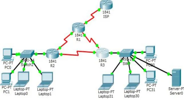
Imagen 1. Topología de red ... 13
Imagen 2. Ping de la Laptop30 al Server0 ... 34
Imagen 3. DHCP y DHCPv6 en PC30 ... 34
Imagen 4. DHCP y DHCPv6 en PC31 ... 35
Imagen 5. DHCP y DHCPv6 en Laptop30 ... 35
Imagen 6. DHCP y DHCPv6 en Laptop31 ... 35
Imagen 7. Ping del Server0 al R3 ... 38
Imagen 8. Ping del Server0 a la Laptop31 ... 40
Imagen 9. Ping del Servidor0 al R1) ... 40
Imagen 10. Ping del Servidor0 al ISP ... 40
Imagen 11. Ping de la PC30 al ISP ... 41
Imagen 12. Ping de R3 a R2 ... 41
Imagen 13. Ping de R3 a R1 ... 41
Imagen 14. Ping de la Laptop21 a R2... 41
Imagen 15. Ping de la PC30 a la dirección ipv6 de el Server0 ... 42
Imagen 16. Ping de la Laptop31 a la dirección IPV6 de el Server0 ... 42
Imagen 17. Ping de la PC30 a la dirección IPV6 de el Server0 ... 43
Imagen 18. Ping de la PC31 a la dirección IPV6 de el Server0 ... 43
Imagen 19. Topología de red ... 44
Imagen 20. Topología de red ... 45
Imagen 21. Ping de R1 a R2 ... 68
Imagen 22. Ping de R2 A R3 ... 68
Imagen 23. Web Server ... 68
Imagen 24. Ping de Web Server al R2... 69
GLOSARIO
Router: un router es un dispositivo de hardware que permite la interconexión de ordenadores en red.
OSPF: es un protocolo de direccionamiento de tipo enlace-estado, desarrollado para las redes IP y basado en el algoritmo de primera vía más corta (SPF).
Switch: es un dispositivo que permite que la conexión de computadoras y periféricos a la red para que puedan comunicarse entre sí y con otras redes.
IPv6: es la versión 6 del Protocolo de Internet (IP por sus siglas en inglés, Internet Protocol), es el encargado de dirigir y encaminar los paquetes en la red, fue diseñado en los años 70 con el objetivo de interconectar redes.
RESUMEN
11
INTRODUCCIÓN
La implementación de Packet Tracer complementa equipo físico en el aula, al permitir a los estudiantes a crear una red con un número casi ilimitado de dispositivos, fomentar la práctica, el descubrimiento y solución de problemas. El ambiente de aprendizaje basado en la simulación ayuda a los estudiantes a desarrollar habilidades del siglo 21, tales como la toma de decisiones, el pensamiento creativo y crítico y resolución de problemas. Packet Tracer complementa los planes de estudios de Networking Academy, permite a los instructores para enseñar y demostrar fácilmente complejos conceptos técnicos y diseño de sistemas de redes.
12 OBJETIVOS
Objetivo General:
✓ Aplicar los conocimientos adquiridos en el transcurso del diplomado de CCNA, desarrollando cada uno de los escenarios prácticos propuestos.
Objetivos Específicos:
✓ Configurar los parámetros básicos de los dispositivos de red
✓ Deshabilitar los puertos que no se usan en los diferentes dispositivos ✓ Implementar dirección IP en cada uno de los routers
✓ Implementar el direccionamiento IPv4 del servidor DHCP. ✓ Configurar el enrutamiento OSPF
✓ Realizar NAT con sobrecarga sobre una dirección IPV4 publica ✓ Implementar rutas estáticas en algunos dispositivos
✓ Configuración de seguridad en cada uno de los terminales ✓ Configurar IPv6 y verificar la conectividad
✓ Configurar switches con VLAN y enlaces troncales
✓ Configurar routing entre VLAN basado en enlaces troncales
13
DESARROLLO DE LOS ESCENARIOS
Escenario 1
Imagen 1. Topología de red
Tabla 1. Direccionamiento
El administra dor
Interfaces Dirección IP
Máscara de subre d
Gateway predeterminad o
ISP S0/0/0 200.123.211.1 255.255.255.0 N/D
R1
Se0/0/0 200.123.211.2 255.255.255.0 N/D
Se0/1/0 10.0.0.1 255.255.255.25
2
14
Se0/1/1 10.0.0.5 255.255.255.25
2
N/D
R2
Fa0/0,100 192.168.20.1 255.255.255.0 N/D Fa0/0,200 192.168.21.1 255.255.255.0 N/D
Se0/0/0 10.0.0.2 255.255.255.25
2
N/D
Se0/0/1 10.0.0.9 255.255.255.25
2
N/D
R3
Fa0/0
192.168.30.1 255.255.255.0 N/D 2001:db8:130::9C0:8
0F:301
/64 N/D
Se0/0/0 10.0.0.6 255.255.255.25
2
N/D
Se0/0/1 10.0.0.10 255.255.255.25 2
N/D
SW2 VLAN 100 N/D N/D N/D
VLAN 200 N/D N/D N/D
SW3 VLAN1 N/D N/D N/D
PC20 NIC DHCP DHCP DHCP
PC21 NIC DHCP DHCP DHCP
PC30 NIC DHCP DHCP DHCP
PC31 NIC DHCP DHCP DHCP
Laptop20 NIC DHCP DHCP DHCP
Laptop21 NIC DHCP DHCP DHCP
15
Laptop31 NIC DHCP DHCP DHCP
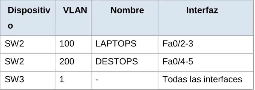
Tabla 2. De asignación de VLAN y de puertos
Dispositiv o
VLAN Nombre Interfaz
SW2 100 LAPTOPS Fa0/2-3
SW2 200 DESTOPS Fa0/4-5
SW3 1 - Todas las interfaces
Tabla 3. Enlaces troncales
Dispositivo local Interfaz local Dispositivo remoto
SW2 Fa0/2-3 100
Situación
16 Descripción de las actividades.
• SW1 VLAN y las asignaciones de puertos de VLAN deben cumplir con la tabla 1.
Configuración de puertos vlan en S2 Switch>enable
Switch#configure terminal
Enter configuration commands, one per line. End with CNTL/Z. Switch(config)#hostname S2
S2(config)#vlan 100
S2(config-vlan)#name LAPTOPS S2(config-vlan)#exit
S2(config)#vlan 200
S2(config-vlan)#name DESTOPS S2(config-vlan)#exit
S2(config)#end S2#
%SYS-5-CONFIG_I: Configured from console by console S2#wr
Building configuration... [OK]
Verificación con el commando show vlan S2#show vlan
VLAN Name Status Ports
1 default active Fa0/1, Fa0/2, Fa0/3, Fa0/4 Fa0/5, Fa0/6, Fa0/7, Fa0/8
17 Fa0/17, Fa0/18, Fa0/19, Fa0/20
Fa0/21, Fa0/22, Fa0/23, Fa0/24 Gig0/1, Gig0/2
100 LAPTOPS active 200 DESTOPS active 1002 fddi-default act/unsup
1003 token-ring-default act/unsup 1004 fddinet-default act/unsup 1005 trnet-default act/unsup
VLAN Type SAID MTU Parent RingNo BridgeNo Stp BrdgMode Trans1 Trans2 ---- --- --- --- --- --- --- ---- --- --- ---
1 enet 100001 1500 - - - 0 0 100 enet 100100 1500 - - - 0 0 200 enet 100200 1500 - - - 0 0 1002 fddi 101002 1500 - - - 0 0 1003 tr 101003 1500 - - - 0 0
1004 fdnet 101004 1500 - - - ieee - 0 0 1005 trnet 101005 1500 - - - ibm - 0 0 Remote SPAN VLANs
--- Primary Secondary Type Ports
--- --- --- ---
Configuración de los puertos Fa0/2-3 y Fa0/4-5 S2#configure terminal
Enter configuration commands, one per line. End with CNTL/Z. S2(config)#int range f0/2-3
18 S2(config-if-range)#switchport mode access S2(config-if-range)#switchport access vlan 200 S2(config-if-range)#exit
S2(config)#end S2#
%SYS-5-CONFIG_I: Configured from console by console S2#wr
Building configuration... [OK]
Verificamos que estén asignadas las vlan a los puertos con el comando show vlan.
S2#show vlan
VLAN Name Status Ports
---- --- --- --- 1 default active Fa0/1, Fa0/6, Fa0/7, Fa0/8
Fa0/9, Fa0/10, Fa0/11, Fa0/12 Fa0/13, Fa0/14, Fa0/15, Fa0/16 Fa0/17, Fa0/18, Fa0/19, Fa0/20 Fa0/21, Fa0/22, Fa0/23, Fa0/24 Gig0/1, Gig0/2
100 LAPTOPS active Fa0/2, Fa0/3 200 DESTOPS active Fa0/4, Fa0/5 1002 fddi-default act/unsup
1003 token-ring-default act/unsup 1004 fddinet-default act/unsup 1005 trnet-default act/unsup
19 1 enet 100001 1500 - - - 0 0
100 enet 100100 1500 - - - 0 0 200 enet 100200 1500 - - - 0 0 1002 fddi 101002 1500 - - - 0 0 1003 tr 101003 1500 - - - 0 0
1004 fdnet 101004 1500 - - - ieee - 0 0 1005 trnet 101005 1500 - - - ibm - 0 0 Remote SPAN VLANs
--- Primary Secondary Type Ports
Configuraciòn de vlan en S3 Switch>enable
Switch#configure terminal
Enter configuration commands, one per line. End with CNTL/Z. Switch(config)#hostname S3
S3(config)#vlan 1 S3(config-vlan)#exit
S3(config)#int range f0/1-24
S3(config-if-range)#switchport mode access S3(config-if-range)#switchport access vlan 1 S3(config-if-range)#exit
S3(config)#end S3#
%SYS-5-CONFIG_I: Configured from console by console S3#wr
20 Verificamos con el comando show vlan S3#show vlan
VLAN Name Status Ports
1 default active Fa0/1, Fa0/2, Fa0/3, Fa0/4 Fa0/5, Fa0/6, Fa0/7, Fa0/8
Fa0/9, Fa0/10, Fa0/11, Fa0/12 Fa0/13, Fa0/14, Fa0/15, Fa0/16 Fa0/17, Fa0/18, Fa0/19, Fa0/20 Fa0/21, Fa0/22, Fa0/23, Fa0/24 Gig0/1, Gig0/2
1002 fddi-default act/unsup
1003 token-ring-default act/unsup 1004 fddinet-default act/unsup 1005 trnet-default act/unsup
VLAN Type SAID MTU Parent RingNo BridgeNo Stp BrdgMode Trans1 Trans2 ---- --- --- --- --- --- --- ---- --- --- ---
1 enet 100001 1500 - - - 0 0 1002 fddi 101002 1500 - - - 0 0 1003 tr 101003 1500 - - - 0 0
1004 fdnet 101004 1500 - - - ieee - 0 0 1005 trnet 101005 1500 - - - ibm - 0 0 Remote SPAN VLANs
Primary Secondary Type Ports
• Los puertos de red que no se utilizan se deben deshabilitar.
Deshabilitar puertos en S3 S3#configure terminal
21 S3(config)#int range f0/7-24
S3(config-if-range)#shutdown
%LINK-5-CHANGED: Interface FastEthernet0/7, changed state to administratively down
%LINK-5-CHANGED: Interface FastEthernet0/8, changed state to administratively down
%LINK-5-CHANGED: Interface FastEthernet0/9, changed state to administratively down
%LINK-5-CHANGED: Interface FastEthernet0/10, changed state to administratively down
%LINK-5-CHANGED: Interface FastEthernet0/11, changed state to administratively down
%LINK-5-CHANGED: Interface FastEthernet0/12, changed state to administratively down
%LINK-5-CHANGED: Interface FastEthernet0/13, changed state to administratively down
%LINK-5-CHANGED: Interface FastEthernet0/14, changed state to administratively down
%LINK-5-CHANGED: Interface FastEthernet0/15, changed state to administratively down
%LINK-5-CHANGED: Interface FastEthernet0/16, changed state to administratively down
%LINK-5-CHANGED: Interface FastEthernet0/17, changed state to administratively down
%LINK-5-CHANGED: Interface FastEthernet0/18, changed state to administratively down
%LINK-5-CHANGED: Interface FastEthernet0/19, changed state to administratively down
22
%LINK-5-CHANGED: Interface FastEthernet0/21, changed state to administratively down
%LINK-5-CHANGED: Interface FastEthernet0/22, changed state to administratively down
%LINK-5-CHANGED: Interface FastEthernet0/23, changed state to administratively down
%LINK-5-CHANGED: Interface FastEthernet0/24, changed state to administratively down
S3(config-if-range)#exit S3(config)#end
S3#
%SYS-5-CONFIG_I: Configured from console by console S3#wr
Building configuration... [OK]
Deshabilitar los puertos en S2 S2#configure terminal
Enter configuration commands, one per line. End with CNTL/Z. S2(config)#int range f0/6-24
S2(config-if-range)#shutdown
%LINK-5-CHANGED: Interface FastEthernet0/6, changed state to administratively down
%LINK-5-CHANGED: Interface FastEthernet0/7, changed state to administratively down
%LINK-5-CHANGED: Interface FastEthernet0/8, changed state to administratively down
23
%LINK-5-CHANGED: Interface FastEthernet0/10, changed state to administratively down
%LINK-5-CHANGED: Interface FastEthernet0/11, changed state to administratively down
%LINK-5-CHANGED: Interface FastEthernet0/12, changed state to administratively down
%LINK-5-CHANGED: Interface FastEthernet0/13, changed state to administratively down
%LINK-5-CHANGED: Interface FastEthernet0/14, changed state to administratively down
%LINK-5-CHANGED: Interface FastEthernet0/15, changed state to administratively down
%LINK-5-CHANGED: Interface FastEthernet0/16, changed state to administratively down
%LINK-5-CHANGED: Interface FastEthernet0/17, changed state to administratively down
%LINK-5-CHANGED: Interface FastEthernet0/18, changed state to administratively down
%LINK-5-CHANGED: Interface FastEthernet0/19, changed state to administratively down
%LINK-5-CHANGED: Interface FastEthernet0/20, changed state to administratively down
%LINK-5-CHANGED: Interface FastEthernet0/21, changed state to administratively down
%LINK-5-CHANGED: Interface FastEthernet0/22, changed state to administratively down
%LINK-5-CHANGED: Interface FastEthernet0/23, changed state to administratively down
24 S2(config-if-range)#exit
S2(config)#end S2#
%SYS-5-CONFIG_I: Configured from console by console S2#wr
Building configuration... [OK]
Configuración Troncales en S2 S2#configure terminal
Enter configuration commands, one per line. End with CNTL/Z. S2(config)#int f0/1
S2(config-if)#switchport mode trunk S2(config-if)#exit
S2(config)#end S2#
%SYS-5-CONFIG_I: Configured from console by console S2#wr
Building configuration... [OK]
Configuración Troncales en S3 S3#configure terminal
Enter configuration commands, one per line. End with CNTL/Z. S3(config)#int f0/1
25
%LINEPROTO-5-UPDOWN: Line protocol on Interface FastEthernet0/1, changed state to down
%LINEPROTO-5-UPDOWN: Line protocol on Interface FastEthernet0/1, changed state to up
exit
S3(config)#exit S3#
%SYS-5-CONFIG_I: Configured from console by console S3#wr
Building configuration... [OK]
• La información de dirección IP R1, R2 y R3 debe cumplir con la tabla 1. Configuración del ISP
Router> enable Router# config t
Enter configuration commands, one per line. End with CNTL/Z. Router(config)# hostname ISP
ISP(config)#int s0/0/0
ISP(config-if)# ip address 200.123.211.1 255.255.255.0 ISP(config-if)# no shut
Configuración en R1 Router>enable Router#config t
Enter configuration commands, one per line. End with CNTL/Z. Router(config)# hostname R1
26
R1(config-if)# ip address 200.123.211.2 255.255.255.0 R1(config-if)# clock rate 128000 R1(config-if)# no shut %LINK-5-CHANGED: Interface Serial0/0/0, changed state to down R1(config-if)# int s0/1/0 R1(config-if)# ip addres 10.0.0.1 255.255.255.252
R1(config-if)# clock rate 128000 This command applies only to DCE interfaces R1(config-if)# no shut R1(config-if)# %LINK-5-CHANGED: Interface Serial0/1/0, changed state to up
%LINEPROTO-5-UPDOWN: Line protocol on Interface Serial0/1/0, changed state to up R1(config-if)# int s0/1/1
R1(config-if)#ip address 10.0.0.5 255.255.255.252 R1(config-if)#clock rate 128000 This command applies only to DCE interfaces R1(config-if)#no shut R1# copy run start Destination filename [startup-config]? Building configuration... [OK] R1#
Configuración en R2 R2(config)# int s0/0/0
R2(config-if)# ip address 10.0.0.2 % Incomplete command.
27 This command applies only to DCE interfaces R2(config-if)# no shut
%LINK-5-CHANGED: Interface Serial0/0/0, changed state to down R2(config-if)# int s0/0/1
R2(config-if)# ip address 10.0.0.9 255.255.255.252 R2(config-if)# clock rate 128000
R2(config-if)# no shut
Configuración en R3 Router> enable
Router# config t
Enter configuration commands, one per line. End with CNTL/Z. Router(config)# hostname R3
R3(config)#int f0/0
R3(config-if)# ip address 192.168.30.1 255.255.255.0 R3(config-if)# no shut
R3(config-if)#
%LINK-5-CHANGED: Interface FastEthernet0/0, changed state to up
%LINEPROTO-5-UPDOWN: Line protocol on Interface FastEthernet0/0, changed state to up
R3(config-if)# int s0/0/0
R3(config-if)# ip address 10.0.0.6 255.255.255.252 R3(config-if)# clock rate 128000
R3(config-if)# no shut R3(config-if)#
%LINK-5-CHANGED: Interface Serial0/0/0, changed state to up R3(config-if)# int s
%LINEPROTO-5-UPDOWN: Line protocol on Interface Serial0/0/0, changed state R3(config-if)# int s0/0/1
28 R3(config-if)#clock rate 128000
R3(config-if)# no shut
• Laptop20, Laptop21, PC20, PC21, Laptop30, Laptop31, PC30 y PC31 deben obtener información IPv4 del servidor DHCP.
Configuración de DHCP en los dispositivos
Configuración en la Laptop20
Activamos la casilla DHCP y nos queda de la siguiente manera
IP Address:192.168.20.2 Mascara de subred:255.255.255.0 Gateway predeterminado: 192.168.20.1 DNS Server: 200.123.211.1
Configuración en la Laptop20
Activamos la casilla DHCP y nos queda de la siguiente manera IP Address: 192.168.21.2 Mascara de subred: 255.255.255. Gateway predeterminado: 192.168.21.1 DNS Server: 200.123.211.1
Configuración en la PC20
Activamos la casilla DHCP y nos queda de la siguiente manera IP Address: 192.168.20.2 Mascara de subred: 255.255.255.0
29 Configuración en la PC21
Activamos la casilla DHCP y nos queda de la siguiente manera IP Address: 192.168.21.2 Mascara de subred: 255.255.255.0 Gateway predeterminado: 192.168.21.1 DNS Server: 200.123.211.1
Configuración en la Laptop30
Activamos la casilla DHCP y nos queda de la siguiente manera IP Address: 192.168.30.5 Mascara de subred: 255.255.255.0 Gateway predeterminado: 0.0.0.0
Configuración en la Laptop31
Activamos la casilla DHCP y nos queda de la siguiente manera IP Address: 192.168.30.2
Macara de subred: 255.255.255.0 Gateway predeterminado: 0.0.0.0
Configuración en la PC30
Activamos la casilla DHCP y nos queda de la siguiente manera IP Address: 192.168.30.4 Mascara de subred: 255.255.255.0 Gateway predeterminado: 0.0.0.0
Configuración en la PC31
30
Mascara de subred: 255.255.255.0 Gateway predeterminado: 0.0.0.0
Configuración en la server0
Activamos la casilla DHCP y nos queda de la siguiente manera IP Address: 192.168.30.6
Macara de subred: 255.255.255.0 Gateway predeterminado: 0.0.0.0
• R1 debe realizar una NAT con sobrecarga sobre una dirección IPv4 pública. Asegúrese de que todos los terminales pueden comunicarse con Internet pública (haga ping a la dirección ISP) y la lista de acceso estándar se llama INSIDE-DEVS.
Configuraciòn NAT R1#configure terminal
Enter configuration commands, one per line. End with CNTL/Z. R1(config)#int s0/1/1
R1(config-if)#ip nat inside R1(config-if)#exit
R1(config)#int s0/1/0 R1(config-if)#ip nat inside R1(config-if)#exit
R1(config)#int s0/0/0 R1(config-if)#ip nat outside R1(config-if)#exit
31
R1(config)#ip nat pool INSIDE-DEVS 200.123.211.2 200.123.211.128 netmask 255.255.255.0
R1(config)#access-list 1 permit 192.168.0.0 0.0.255.255 R1(config)#access-list 1 permit 10.0.0.0 0.255.255.255
R1(config)#ip nat inside source list 1 interface s0/0/0 overload
R1(config)#ip nat inside source static tcp 192.168.30.6 80 200.123.211.1 80 R1(config)#router rip
R1(config-router)#version 2
R1(config-router)#network 10.0.0.0 R1(config-router)#exit
R1(config)#end R1#
%SYS-5-CONFIG_I: Configured from console by console R1#wr
Building configuration... [OK]
Verificamos con el conmando show ip nat translations R1#show ip nat translations
Pro Inside global Inside local Outside local Outside global tcp 200.123.211.1:80 192.168.30.6:80 --- ---
verificación de la ruta estática e interfaces de salida y de entrada show ip nat statistics
R1#show ip nat statistics
Total translations: 1 (1 static, 0 dynamic, 1 extended) Outside Interfaces: Serial0/0/0
32 Expired translations: 0
Dynamic mappings:
• R1 debe tener una ruta estática predeterminada al ISP que se configuró y que incluye esa ruta en el dominio RIPv2.
Ruta estàtica en R1
R1(config)#ip nat inside source static tcp 192.168.30.6 80 200.123.211.1 80 R1(config)#router rip
R1(config-router)#version 2
R1(config-router)#network 10.0.0.0 R1(config-router)#exit
R1(config)#end R1#
%SYS-5-CONFIG_I: Configured from console by console R1#wr
Building configuration... [OK]
• R2 es un servidor de DHCP para los dispositivos conectados al puerto FastEthernet0/0.
R2>enable
R2#configure terminal
Enter configuration commands, one per line. End with CNTL/Z. R2(config)#ip dhcp excluded-address 10.0.0.2 10.0.0.9
R2(config)#ip dhcp pool INSIDE-DEVS
33 R2(dhcp-config)#default-router 192.168.1.1 R2(dhcp-config)#dns
% Incomplete command.
R2(dhcp-config)#dns-server 0.0.0.0 R2(dhcp-config)#exit
R2(config)#end R2#
%SYS-5-CONFIG_I: Configured from console by console R2#wr
Building configuration... [OK]
• R2 debe, además de enrutamiento a otras partes de la red, ruta entre las VLAN
R2#configure terminal
Enter configuration commands, one per line. End with CNTL/Z. R2(config)#int vlan 100
R2(config-if)#ip address 192.168.20.1 255.255.255.0 % 192.168.20.0 overlaps with FastEthernet0/0.100 R2(config-if)#exit
R2(config)#int vlan 200
R2(config-if)#ip address 192.168.21.1 255.255.255.0 % 192.168.21.0 overlaps with FastEthernet0/0.200 R2(config-if)#end
R2#
%SYS-5-CONFIG_I: Configured from console by console R2#wr
34 [OK]
• El Servidor0 es sólo un servidor IPv6 y solo debe ser accesibles para los dispositivos en R3 (ping).
R3(config)# ipv6 unicast-routing R3(config)# int f0/0
R3(config-if)#ipv6 address 200:db8:130::9c0:80F:301/64 R3(config-if)# exit
R3(config)# int f0/0
Imagen 2. Ping de la Laptop30 al Server0
• La NIC instalado en direcciones IPv4 e IPv6 de Laptop30, de Laptop31, de PC30 y obligación de configurados PC31 simultáneas (dual-stack). Las direcciones se deben configurar mediante DHCP y DHCPv6.
35 Imagen 4. DHCP y DHCPv6 en PC31
Imagen 5. DHCP y DHCPv6 en Laptop30
Imagen 6. DHCP y DHCPv6 en Laptop31
36
• La interfaz FastEthernet f 0/0 del R3 también deben tener direcciones IPv4 e IPv6 configuradas (dual- stack).
R3#configure terminal
Enter configuration commands, one per line. End with CNTL/Z. R3(config)#ipv6 unicast-routing
R3(config)#int f0/0
R3(config-if)#ip address 192.168.30.1 255.255.255.0 R3(config-if)#ipv6 address 2001:db8::9C0:80F:301/64 R3(config-if)#no shutdown
R3(config-if)#exit R3(config)#end R3#
%SYS-5-CONFIG_I: Configured from console by console R3#wr
Building configuration... [OK]
• R1, R2 y R3 intercambian información de routing mediante RIP versión 2.
R3# show ip route
Configuración en R1 R1#configure terminal
Enter configuration commands, one per line. End with CNTL/Z. R1(config)#router rip
R1(config-router)#version 2
37
C 200.123.211.0/24 is directly connected, Serial0/0/0 R1(config-router)#network 10.0.0.0
R1(config-router)#network 10.0.0.4 R1(config-router)#end
R1#
%SYS-5-CONFIG_I: Configured from console by console R1#wr
Building configuration... [OK]
Configuración en R2 R2#configure terminal
Enter configuration commands, one per line. End with CNTL/Z. R2(config)#router rip
R2(config-router)#version 2
R2(config-router)#network 10.0.0.0 R2(config-router)#network 10.0.0.8
R2(config-router)#do show ip route connected C 10.0.0.0/30 is directly connected, Serial0/0/0 C 10.0.0.8/30 is directly connected, Serial0/0/1
C 192.168.20.0/24 is directly connected, FastEthernet0/0.100 C 192.168.21.0/24 is directly connected, FastEthernet0/0.200 R2(config-router)#end
R2#
%SYS-5-CONFIG_I: Configured from console by console R2#wr
38 Configuración en R3
R3#configure terminal
Enter configuration commands, one per line. End with CNTL/Z. R3(config)#router rip
R3(config-router)#version 2
R3(config-router)#network 10.0.0.0 R3(config-router)#network 10.0.0.8 R3(config-router)#end
R3#show ip route connected
C 10.0.0.4/30 is directly connected, Serial0/0/0 C 10.0.0.8/30 is directly connected, Serial0/0/1
C 192.168.30.0/24 is directly connected, FastEthernet0/0 R3#wr
Building configuration... [OK]
• R1, R2 y R3 deben saber sobre las rutas de cada uno y la ruta predeterminada desde R1.
R1#show protocol Global values:
Internet Protocol routing is enabled
FastEthernet0/0 is administratively down, line protocol is down FastEthernet0/1 is administratively down, line protocol is down Serial0/0/0 is up, line protocol is up
Internet address is 200.123.211.2/24
Serial0/0/1 is administratively down, line protocol is down Serial0/1/0 is up, line protocol is up
39 Serial0/1/1 is up, line protocol is up
Internet address is 10.0.0.5/30
Vlan1 is administratively down, line protocol is down
• Verifique la conectividad. Todos los terminales deben poder hacer ping entre sí y a la dirección IP del ISP. Los terminales bajo el R3 deberían poder hacer ipv6-ping entre ellos y el servidor.
40 Imagen 8. Ping del Server0 a la Laptop31
Imagen 9. Ping del Servidor0 al R1)
41 Imagen 11. Ping de la PC30 al ISP
Imagen 12. Ping de R3 a R2
Imagen 13. Ping de R3 a R1
42
Imagen 15. Ping de la PC30 a la dirección ipv6 de el Server0
43
Imagen 17. Ping de la PC30 a la dirección IPV6 de el Server0
44
ESCENARIO 2
Una empresa de Tecnología posee tres sucursales distribuidas en las ciudades de Miami, Bogotá y Buenos Aires, en donde el estudiante será el administrador de la red, el cual deberá configurar e interconectar entre sí cada uno de los dispositivos que forman parte del escenario, acorde con los lineamientos establecidos para el direccionamiento IP, protocolos de enrutamiento y demás aspectos que forman parte de la topología de red.
45
1. Configurar el direccionamiento IP acorde con la topología de red para cada uno de los dispositivos que forman parte del escenario
Realizamos la topología como se muestra en la figura
Imagen 20. Topología de red
Configuración del direccionamiento ip de “Internet PC”
Seleccionamos la configuración IP estática y configuramos lo siguiente: IP address: 209.165.200.230
Mascara de subred: 255.255.255.248 Gateway predeterminado: 209.165.200.225
Configuración de “Web Server”
Seleccionamos la configuración IP estática y configuramos lo siguiente: IP address: 10.10.10.10
46 Configuración de “R1”
Router>enable
Router#configure terminal
Enter configuration commands, one per line. End with CNTL/Z. Router(config)#hostname R1
R1(config)#int s0/0/0
R1(config-if)#description connection to R2
R1(config-if)#ip add 172.31.21.1 255.255.255.252 R1(config-if)#clock rate 128000
R1(config-if)#no shutdown
%LINK-5-CHANGED: Interface Serial0/0/0, changed state to down R1(config-if)#
R1(config-if)#exit
R1(config)#ip route 0.0.0.0 0.0.0.0 s0/0/0 R1(config)#
Configuración del “R2” Router>enable
Router#configure terminal
Enter configuration commands, one per line. End with CNTL/Z. Router(config)#hostname R2
R2(config)#int s0/0/1
R2(config-if)#descrip connection to R1
R2(config-if)#ip add 172.31.21.2 255.255.255.252 R2(config-if)#no shutdown
R2(config-if)#
%LINK-5-CHANGED: Interface Serial0/0/1, changed state to up
%LINEPROTO-5-UPDOWN: Line protocol on Interface Serial0/0/1, changed state to up
47 R2(config-if)#descrip connection to R3
R2(config-if)#ip add 172.31.23.1 255.255.255.252 R2(config-if)#clock rate 128000
R2(config-if)#no shutdown
%LINK-5-CHANGED: Interface Serial0/0/0, changed state to down R2(config-if)#int f0/0
R2(config-if)#descrip Internet PC
R2(config-if)#ip add 209.165.200.225 255.255.255.248 R2(config-if)#no shutdown
R2(config-if)#
%LINK-5-CHANGED: Interface FastEthernet0/0, changed state to up
%LINEPROTO-5-UPDOWN: Line protocol on Interface FastEthernet0/0, changed state to up
R2(config-if)#int f0/1
R2(config-if)#ip address 10.10.10.1 255.255.255.0 R2(config-if)#no shutdown
R2(config-if)#
%LINK-5-CHANGED: Interface FastEthernet0/1, changed state to up
%LINEPROTO-5-UPDOWN: Line protocol on Interface FastEthernet0/1, changed state to up
R2(config-if)#description connection to web server R2(config-if)#exit
R2(config)#ip route 0.0.0.0 0.0.0.0 f0/0 R2(config)#
%LINK-5-CHANGED: Interface Serial0/0/0, changed state to up
48 Configuración del “R3”
Router>enable
Router#configure terminal
Enter configuration commands, one per line. End with CNTL/Z. Router(config)#hostname R3
R3(config)#int s0/0/1
R3(config-if)#description connection to R2
R3(config-if)#ip add 172.31.23.2 255.255.252.252 Bad mask 0xFFFFFCFC for address 172.31.23.2 R3(config-if)#ip add 172.31.23.2 255.255.255.252 R3(config-if)#no shutdown
R3(config-if)#
%LINK-5-CHANGED: Interface Serial0/0/1, changed state to up R3(config-if)#int lo4
R3(config-if)#
%LINK-5-CHANGED: Interface Loopback4, changed state to up
%LINEPROTO-5-UPDOWN: Line protocol on Interface Loopback4, changed state to up
R3(config-if)#ip address 192.168.4.1 255.255.255.0 R3(config-if)#no shutdown
R3(config-if)#int lo5 R3(config-if)#
%LINK-5-CHANGED: Interface Loopback5, changed state to up
%LINEPROTO-5-UPDOWN: Line protocol on Interface Loopback5, changed state to up
R3(config-if)#ip add 192.168.5.1 255.255.255.0 R3(config-if)#no shutdown
R3(config-if)#int lo6 R3(config-if)#
49
%LINEPROTO-5-UPDOWN: Line protocol on Interface Loopback6, changed state to up
R3(config-if)#ip add 192.168.6.1 255.255.255.0 R3(config-if)#exit
R3(config)#ip route 0.0.0.0 0.0.0.0 s0/0/1 R3(config)#
Configuración de “S1” Switch>enable
Switch#configure terminal
Enter configuration commands, one per line. End with CNTL/Z. Switch(config)#no ip domain-lookup
Switch(config)#hostname S1 S1(config)#exit
S1#
%SYS-5-CONFIG_I: Configured from console by console
Configuración de “S3” Switch>enable
Switch#configure terminal
Enter configuration commands, one per line. End with CNTL/Z. Switch(config)#no ip domain-lookup
Switch(config)#hostname S3 S3(config)#exit
S3#
50
Configuración del direccionamiento ip de “PC-A”
Seleccionamos la configuración IP por DHCP y nos queda de la siguiente manera: IP address: 169.254.139.60
Mascara de subred: 255.255.0.0 Gateway predeterminado: 0.0.0.0
Configuración del direccionamiento ip de “PC-C”
Seleccionamos la configuración IPpor DHCP y nos queda de la siguiente manera: IP address: 169.254.236.160
Mascara de subred: 255.255.0.0 Gateway predeterminado: 0.0.0.0
2. Configurar el protocolo de enrutamiento OSPFv2 bajo los siguientes criterios:
Tabla 4. OSPFv2 área 0
Configuration Item or Task Specification
Router ID R1 1.1.1.1
Router ID R2 5.5.5.5
Router ID R3 8.8.8.8
Configurar todas las interfaces LAN como pasivas
Establecer el ancho de banda para enlaces
seriales en 256 Kb/s
51 Configuración en R1
R1>enable
R1#configure terminal
Enter configuration commands, one per line. End with CNTL/Z. R1(config)#router ospf 1
R1(config-router)#router-id 1.1.1.1
R1(config-router)#Reload or use "clear ip ospf process" command, for this to take effect
R1(config-router)#no router-id 1.1.1.1 R1(config-router)#router-id 1.1.1.1
R1(config-router)#Reload or use "clear ip ospf process" command, for this to take effect
R1(config-router)#network 172.31.21.0 0.0.0.3 area 0 R1(config-router)#network 192.168.30.0 0.0.0.255 area 0 R1(config-router)#network 192.168.40.0 0.0.0.255 area 0 R1(config-router)#network 192.168.200.0 0.0.0.255 area 0 R1(config-router)#passive-interface f0/0
R1(config-router)#exit R1(config)#int s0/0/0
R1(config-if)#bandwidth 256 R1(config-if)#ip ospf cost 9500 R1(config-if)#
Configuración en R2 R2>enable
R2#configure terminal
Enter configuration commands, one per line. End with CNTL/Z. R2(config)#router ospf 1
52
R2(config-router)#network 172.31.21.0 0.0.0.3 area 0 R2(config-router)#
02:12:01: %OSPF-5-ADJCHG: Process 1, Nbr 1.1.1.1 on Serial0/0/1 from LOADING to FULL, Loading Done
R2(config-router)#network 172.31.23.0 0.0.0.3 area 0 R2(config-router)#network 172.31.23.0 0.0.0.3 area 0 R2(config-router)#network 172.31.21.0 0.0.0.3 area 0 R2(config-router)#network 10.10.10.0 0.0.0.255 area 0 R2(config-router)#passive-interface f0/0
R2(config-router)#interface s0/0/0 R2(config-if)#bandwidth 256 R2(config-if)#interface s0/0/1 R2(config-if)#bandwidth 256 R2(config-if)#interface s0/0/0 R2(config-if)#ip ospf cost 7500 R2(config-if)#
Configuración en R3 R3>enable
R3#configure terminal
Enter configuration commands, one per line. End with CNTL/Z. R3(config)#router ospf 1
R3(config-router)#router-id 8.8.8.8
R3(config-router)#network 172.31.23.0 0.0.0.3 area 0 R3(config-router)#
02:25:30: %OSPF-5-ADJCHG: Process 1, Nbr 5.5.5.5 on Serial0/0/1 from LOADING to FULL, Loading Done
53 R3(config-router)#passive-interface lo5 R3(config-router)#passive-interface lo6 R3(config-router)#exit
R3(config)#int s0/0/1
R3(config-if)#bandwidth 256 R3(config-if)#ip ospf cost 9500 R3(config-if)#exit
Verificar información de OSPF
• Visualizar tablas de enrutamiento y routers conectados por OSPFv2 R2>enable
R2#show ip ospf neighbor
Neighbor ID Pri State Dead Time Address Interface 1.1.1.1 0 FULL/ - 00:00:30 172.31.21.1 Serial0/0/1 8.8.8.8 0 FULL/ - 00:00:39 172.31.23.2 Serial0/0/0
• Visualizar lista resumida de interfaces por OSPF en donde se ilustre el costo de cada interface
Para este paso se utiliza el comando show ip ospf interface brief pero este comando no es soportado por Packet tracert
R2#show ip ospf interface brief ^
54
• Visualizar el OSPF Process ID, Router ID, Address summarizations, Routing Networks, and passive interfaces configuradas en cada router.
R2#show ip protocols Routing Protocol is "ospf 1"
Outgoing update filter list for all interfaces is not set Incoming update filter list for all interfaces is not set Router ID 5.5.5.5
Number of areas in this router is 1. 1 normal 0 stub 0 nssa Maximum path: 4
Routing for Networks: 172.31.21.0 0.0.0.3 area 0 172.31.23.0 0.0.0.3 area 0 10.10.10.0 0.0.0.255 area 0 Passive Interface(s):
FastEthernet0/0
Routing Information Sources: Gateway Distance Last Update 1.1.1.1 110 00:28:05
5.5.5.5 110 00:17:56 8.8.8.8 110 00:13:05 Distance: (default is 110)
55 Primero configuramos la seguridad en R1 R1>enable
R1#configure terminal
Enter configuration commands, one per line. End with CNTL/Z. R1(config)#enable secret class
R1(config)#line con 0 R1(config-line)#pass cisco R1(config-line)#login R1(config-line)#line vty 0 4 R1(config-line)#pass cisco R1(config-line)#login R1(config-line)#exit R1(config)#service pass
R1(config)#service password-encryption
R1(config)#banner motd #Prohibido El Acceso No Autorizado# R1(config)# exit
R1#copy running-config startup-config Destination filename [startup-config]? Building configuration...
[OK]
Seguridad en el router R2 R2>enable
R2#configure terminal
Enter configuration commands, one per line. End with CNTL/Z. R2(config)#enable secret class
56 R2(config-line)#pass cisco
R2(config-line)#login R2(config-line)#exit
R2(config)#service password-encryption
R2(config)#banner motd #Prohibido El Acceso No Autorizado# R2(config)#exit
R2#
%SYS-5-CONFIG_I: Configured from console by console R2#copy running-config startup-config
Destination filename [startup-config]? Building configuration...
[OK]
Configuración de seguridad en R3 R3>enable
R3#configure terminal
Enter configuration commands, one per line. End with CNTL/Z. R3(config)#enable secret class
R3(config)#line con 0 R3(config-line)#pass cisco R3(config-line)#login R3(config-line)#exit
R3(config)#service password-encryption
R3(config)#banner motd #Prohibido El Acceso No Autorizado# R3(config)#exit
R3#
%SYS-5-CONFIG_I: Configured from console by console R3#copy running-config startup-config
57 [OK]
Configuración de seguridad en S1 S1>enable
Password:
S1#configure terminal
Enter configuration commands, one per line. End with CNTL/Z. S1(config)#enable secret class
S1(config)#line con 0 S1(config-line)#pass cisco S1(config-line)#login S1(config-line)#line vty 0 4 S1(config-line)#pass cisco S1(config-line)#login
S1(config-line)#service password-encryption
S1(config)#banner motd #Prohibido El Acceso No Autorizado# S1(config)#exit
S1#
%SYS-5-CONFIG_I: Configured from console by console S1#copy running-config startup-config
Destination filename [startup-config]? Building configuration...
[OK]
Seguridad en S3 S3>enable
S3#configure terminal
Enter configuration commands, one per line. End with CNTL/Z. S3(config)#hostname S3
58 S3(config)#enable secret class
S3(config)#line con 0 S3(config-line)#pass cisco S3(config-line)#login S3(config-line)#line vty 0 4 S3(config-line)#pass cisco S3(config-line)#login S3(config-line)#exit
S3(config)#service password-encryption
S3(config)#banner motd #Prohibido El Acceso No Autorizado# S3(config)#exit
S3#
%SYS-5-CONFIG_I: Configured from console by console
Configuraciòn de vlan en S1 S1#configure terminal
Enter configuration commands, one per line. End with CNTL/Z. S1(config)#no ip domain-lookup
S1(config)#vlan 30
S1(config-vlan)#name Administracion S1(config-vlan)#vlan 40
S1(config-vlan)#name Mercadeo S1(config-vlan)#vlan 200
S1(config-vlan)#name Mantenimiento S1(config-vlan)#exit
S1(config)#int vlan 200 S1(config-if)#
%LINK-5-CHANGED: Interface Vlan200, changed state to up S1(config-if)#ip address 192.168.200.2 255.255.255.0
59 S1(config-if)#exit
S1(config)#ip default-gateway 192.168.200.1 S1(config)#interface f0/3
S1(config-if)#switchport mode trunk S1(config-if)#
%LINEPROTO-5-UPDOWN: Line protocol on Interface FastEthernet0/3, changed state to down
%LINEPROTO-5-UPDOWN: Line protocol on Interface FastEthernet0/3, changed state to up
%LINEPROTO-5-UPDOWN: Line protocol on Interface Vlan200, changed state to up
S1(config-if)#switchport trunk native vlan 1 S1(config-if)#interface f0/24
S1(config-if)#switchport mode trunk
S1(config-if)#switchport trunk native vlan 1
S1(config-if)#interface range fa0/1-2, fa0/4-23, GigabitEthernet0/1-2 S1(config-if-range)#switchport mode access
S1(config-if-range)#interface fa0/1 S1(config-if)#switchport mode access S1(config-if)#switchport access vlan 30
S1(config-if)#interface range fa0/2, fa0/4-23, GigabitEthernet0/1-2 S1(config-if-range)#no shutdown
Configuración vlan en S3
Prohibido El Acceso No Autorizado User Access Verification
Password: S3>enable Password:
60
Enter configuration commands, one per line. End with CNTL/Z. S3(config)#hostname S3
S3(config)#no ip domain-lookup S3(config)#vlan 30
S3(config-vlan)#name Administracion S3(config-vlan)#vlan 40
S3(config-vlan)#name Mercadeo S3(config-vlan)#vlan 200
S3(config-vlan)#name Mantenimiento S3(config-vlan)#exit
S3(config)#int vlan 200 S3(config-if)#
%LINK-5-CHANGED: Interface Vlan200, changed state to up
%LINEPROTO-5-UPDOWN: Line protocol on Interface Vlan200, changed state to up
S3(config-if)#ip address 192.168.200.3 255.255.255.0 S3(config-if)#no shutdown
S3(config-if)#exit
S3(config)#ip default-gateway 192.168.200.1 S3(config)#interface f0/3
S3(config-if)#switchport mode trunk
S3(config-if)#switchport trunk native vlan 1
S3(config-if)#interface range fa0/1-2, fa0/4-24, GigabitEthernet0/1-2 S3(config-if-range)#switchport mode access
S3(config-if-range)#interface fa0/1 S3(config-if)#switchport mode access S3(config-if)#switchport access vlan 40 S3(config-if)#
61
4. En el Switch 3 deshabilitar DNS lookup
S3#configure terminal
Enter configuration commands, one per line. End with CNTL/Z. S3(config)#no ip domain-lookup
S3(config)#exit S3#
%SYS-5-CONFIG_I: Configured from console by console
5. Asignar direcciones IP a los Switches acorde a los lineamientos.
Configuración de direcciones IP en S1 S1#configure terminal
Enter configuration commands, one per line. End with CNTL/Z. S1(config)#int vlan 200
S1(config-if)#ip address 192.168.200.2 255.255.255.0 S1(config-if)#no shutdown
S1(config-if)#exit
S1(config)#ip default-gateway 192.168.200.1
Configuración de direcciones IP en S3 Prohibido El Acceso No Autorizado User Access Verification
Password: S3>enable Password:
S3#configure terminal
Enter configuration commands, one per line. End with CNTL/Z. S3(config)#int vlan 200
62 S3(config-if)#no shutdown
S3(config-if)#exit
S3(config)#ip default-gateway 192.168.200.1 S3(config)#
6. Desactivar todas las interfaces que no sean utilizadas en el esquema de red.
Desactivar interfaces en S1 S1#configure terminal
Enter configuration commands, one per line. End with CNTL/Z. S1(config)#
S1(config)#interface range fa0/1-2, fa0/4-23, GigabitEthernet0/1-2 S1(config-if-range)#switchport mode access
S1(config-if-range)#interface fa0/1 S1(config-if)#switchport mode access S1(config-if)#switchport access vlan 30
S1(config-if)#interface range fa0/2, fa0/4-23, GigabitEthernet0/1-2 S1(config-if-range)#shutdown
S1(config-if-range)#
Desactivar interfaces en S3 S3>enable
Password:
S3#configure terminal
Enter configuration commands, one per line. End with CNTL/Z. S3(config)#int vlan 200
63 S3(config-if)#exit
S3(config)#ip default-gateway 192.168.200.1 S3(config)#
S3(config)#interface range fa0/1-2, fa0/4-24, GigabitEthernet0/1-2 S3(config-if-range)#switchport mode access
S3(config-if-range)#int fa0/1
S3(config-if)#switchport mode access S3(config-if)#switchport access vlan 40
S3(config-if)#interface range fa0/2, fa0/4-24, GigabitEthernet0/1-2 S3(config-if-range)#shutdown
S3(config-if-range)#
7. Implement DHCP and NAT for IPv4
Configuraciòn para R1 R1#configure terminal
Enter configuration commands, one per line. End with CNTL/Z. R1(config)#ip dhcp excluded-address 192.168.30.1 192.168.30.30 R1(config)#ip dhcp pool Administracion
R1(dhcp-config)#network 192.168.30.0 255.255.255.0 R1(dhcp-config)#default-router 192.168.30.1
R1(dhcp-config)#dns-server 10.10.10.11 R1(dhcp-config)#end
R1#
%SYS-5-CONFIG_I: Configured from console by console R1#enable
R1#configure terminal
64 R1(config)#ip dhcp pool Mercadeo
R1(dhcp-config)#network 192.168.40.0 255.255.255.0 R1(dhcp-config)#default-router 192.168.40.1
R1(dhcp-config)#dns-server 10.10.10.11 R1(dhcp-config)#end
R1#
%SYS-5-CONFIG_I: Configured from console by console
8. Configurar R1 como servidor DHCP para las VLANs 30 y 40.
R1#configure terminal
Enter configuration commands, one per line. End with CNTL/Z. R1(config)#ip dhcp excluded-address 192.168.30.1 192.168.30.30 R1(config)#ip dhcp excluded-address 192.168.40.1 192.168.40.30 R1(config)#ip dhcp pool ADMINISTRACION
R1(dhcp-config)#dns-server 10.10.10.11
R1(dhcp-config)#domain-name ccna-unad.com ^
% Invalid input detected at '^' marker.
R1(dhcp-config)#default-router 192.168.30.1
R1(dhcp-config)#network 192.168.30.0 255.255.255.0 R1(dhcp-config)#exit
R1(config)#exit
65 Tabla 5. VLAN
Configurar DHCP pool para VLAN 30
Name: ADMINISTRACION DNS-Server: 10.10.10.11 Domain-Name: ccna-unad.com Establecer default gateway.
Configurar DHCP pool para VLAN 40
Name: MERCADEO DNS-Server: 10.10.10.11 Domain-Name: ccna-unad.com Establecer default gateway.
R1#configure terminal
Enter configuration commands, one per line. End with CNTL/Z. R1(config)#ip dhcp excluded-address 192.168.31.1 192.168.31.30 R1(config)#ip dhcp excluded-address 192.168.31.1 192.168.31.30 R1(config)#no ip dhcp excluded-address 192.168.31.1 192.168.31.30 R1(config)#ip dhcp excluded-address 192.168.30.1 192.168.30.30 R1(config)#ip dhcp excluded-address 192.168.40.1 192.168.40.30 R1(config)#ip dhcp pool Administracion
R1(dhcp-config)#dns-server 10.10.10.11
R1(dhcp-config)#domain-name ccna-unad.com ^
% Invalid input detected at '^' marker.
R1(dhcp-config)#default-router 192.168.30.1
R1(dhcp-config)#network 192.168.30.0 255.255.255.0 R1(dhcp-config)#ip dhcp pool Mercadeo
R1(dhcp-config)#dns-server 10.10.10.11
66 % Invalid input detected at '^' marker.
R1(dhcp-config)#default-router 192.168.40.1
R1(dhcp-config)#network 192.168.40.0 255.255.255.0 R1(dhcp-config)#
10.Configurar NAT en R2 para permitir que los hosts puedan salir a internet
R2#configure terminal
Enter configuration commands, one per line. End with CNTL/Z. R2(config)#access-list 1 permit 192.168.30.1 0.0.0.255
R2(config)#access-list 1 permit 192.168.40.1 0.0.0.255 R2(config)#no access-list 1 permit 192.168.30.1 0.0.0.255 R2(config)#no access-list 1 permit 192.168.40.1 0.0.0.255 R2(config)#access-list 1 permit 192.168.30.0 0.0.0.255 R2(config)#access-list 1 permit 192.168.40.0 0.0.0.255 R2(config)#access-list 1 permit 192.168.4.0 0.0.3.255
R2(config)#ip nat pool INTERNET 209.165.200.225 209.165.200.228 netmask 255.255.255.248
R2(config)#ip nat inside source list 1 pool INTERNET
R2(config)#ip nat inside source static 10.10.10.10 209.165.200.229 R2(config)#
11.Configurar al menos dos listas de acceso de tipo estándar a su criterio en para restringir o permitir tráfico desde R1 o R3 hacia R2.
R2#configure terminal
Enter configuration commands, one per line. End with CNTL/Z.
67 R2(config)#int f0/0
R2(config-if)#ip access-group 101 in R2(config-if)#int s0/0/1
R2(config-if)#ip access-group 101 out R2(config-if)#int s0/0/0
R2(config-if)#ip access-group 101 out R2(config-if)#int f0/1
R2(config-if)#ip access-group 101 out R2(config-if)#
12.Configurar al menos dos listas de acceso de tipo extendido o nombradas a su criterio en para restringir o permitir tráfico desde R1 o R3 hacia R2.
R2#configure terminal
Enter configuration commands, one per line. End with CNTL/Z. R2(config)#ip nat inside source static 10.10.10.10 209.165.200.229 R2(config)#int f0/0
R2(config-if)#ip nat outside R2(config-if)#int f0/1
R2(config-if)#ip nat inside R2(config-if)#end
R2#
%SYS-5-CONFIG_I: Configured from console by console R2#configure terminal
Enter configuration commands, one per line. End with CNTL/Z. R2(config)#access-list 1 permit 192.168.30.0 0.0.0.255
R2(config)#access-list 1 permit 192.168.40.0 0.0.0.255 R2(config)#access-list 1 permit 192.168.4.0 0.0.3.255
68
R2(config)#ip nat inside source list 1 pool INTERNET R2(config)#
13.Verificar procesos de comunicación y redireccionamiento de tráfico en los routers mediante el uso de Ping y Traceroute.
Verificación con el comando ping
Imagen 21. Ping de R1 a R2
Imagen 22. Ping de R2 A R3
69 Imagen 24. Ping de Web Server al R2
70
CONCLUSIONES
En esta actividad se retoman conocimientos sobre router, switch, computadores de escritorio y laptops, en los cuales se recopilan aprendizajes sobre cambiar nombres, crear contraseñas, encriptar contraseñas, crear direcciones ip, asignar puertos fastethernet y gigabit, además se realiza diferentes comandos para implementar la seguridad en los switch y routers que permitan conexiones seguras, además se logra realizar las topologías planteadas para esta actividad, con cada uno de sus dispositivos y conexiones necesarias. También se pudo establecer las diferentes encriptaciones y configuraciones a cada uno de los equipos. Configurando cada una de las interfaces asignando la información necesaria para las conexiones IPv4 y IPv6.
De igual manera se logra comprender y adquirir destrezas y conocimientos necesarios en el campo de las redes. También Se pudo realizar las configuraciones solicitadas en la guía, en las cuales se establecieron conexiones mediante VLANs y OSPF.
71
Por otra parte, se pudo configurar las rutas predeterminadas y dinámicas en IPV6 y Se logra habilitar y configurar el direccionamiento en cada uno de los dispositivos, en los cuales se pudo constatar comunicación y se logra afianzar nuestro conocimiento en el manejo y las funciones de cada uno de los diferentes comandos utilizados en esta práctica, los cuales nos ayudan a verificar la conexión como lo es el comando ping.
Por otra parte, en esta actividad reafirmamos lo estudiado en la plataforma cisco donde configuramos las direcciones VLAN, también configuramos las VLAN en los diferentes Switch, además se asignaron las VLAN en los puertos destinados.
Como se ha mostrado se verifican las Vlan igualmente se configuran los puertos de acceso o puertos troncales para que puedan pasar información de Vlan entre los dispositivos intermediarios.
72
BIBLIOGRAFÍA
✓ CISCO. (2014). Introducción a redes conmutadas. Principios d Enrutamiento y
Conmutación. Recuperado de
https://static-course-assets.s3.amazonaws.com/RSE50ES/module1/index.html#1.0.1.1
✓ CISCO. (2014). Configuración y conceptos básicos de Switching. Principios de Enrutamiento y Conmutación. Recuperado de
https://static-course-assets.s3.amazonaws.com/RSE50ES/module2/index.html#2.0.1.1
✓ CISCO. (2014). VLANs. Principios de Enrutamiento y Conmutación. Recuperado
de
https://static-course-assets.s3.amazonaws.com/RSE50ES/module3/index.html#3.0.1.1
✓ CISCO. (2014). Conceptos de Routing. Principios de Enrutamiento y
Conmutación. Recuperado de
https://static-course-assets.s3.amazonaws.com/RSE50ES/module4/index.html#4.0.1.1
✓ CISCO. (2014). Enrutamiento entre VLANs. Principios de Enrutamiento y
Conmutación. Recuperado de
73
✓ CISCO. (2014). Enrutamiento Estático. Principios de Enrutamiento y
Conmutación. Recuperado de
https://static-course-assets.s3.amazonaws.com/RSE50ES/module6/index.html#6.0.1.1
✓ UNAD (2014). Configuración de Switches y Routers [OVA]. Recuperado de
https://1drv.ms/u/s!AmIJYei-NT1IhgL9QChD1m9EuGqC
✓ Macfarlane, J. (2014). Network Routing Basics : Understanding IP Routing in
Cisco Systems. Recuperado de
http://bibliotecavirtual.unad.edu.co:2048/login?url=http://search.ebscohost.com/
login.aspx?direct=true&db=e000xww&AN=158227&lang=es&site=ehost-live