2017
Presentado por
Elvis Aunta
Paso 7 Actividad Colaborativa 4
Carlos Rincon Sanchez
Brayan Andres Moreno
Jimmy Alexander Gallego
Uriel Camilo Parales
Presentado a:
Tutor
Efrain Alejandro Perez
Universidad Nacional Abierta y a Distancia
Escuela de Ciencias Básicas Tecnología e Ingeniería
INTRODUCCION
Las redes de datos que usamos en nuestras vidas cotidianas para aprender, jugar y
trabajar varían desde pequeñas redes locales hasta grandes internetworks globales. En
el hogar, un usuario puede tener un router y dos o más computadoras. En el trabajo, una
organización probablemente tenga varios routers y switches para atender las
necesidades de comunicación de datos de cientos o hasta miles de computadoras.
Los routers reenvían paquetes mediante el uso de la información de la tabla de routing.
Los routers pueden descubrir las rutas hacia las redes remotas de dos maneras: de forma
estática y de forma dinámica.
En una red grande con muchas redes y subredes, la configuración y el mantenimiento
de rutas estáticas entre dichas redes conllevan una sobrecarga administrativa y
operativa. Esta sobrecarga administrativa es especialmente tediosa cuando se producen
cambios en la red, como un enlace fuera de servicio o la implementación de una nueva
subred. Implementar protocolos de routing dinámico puede aliviar la carga de las tareas
de configuración y de mantenimiento, además de proporcionar escalabilidad a la red.
PACKET TRACER - CONFIGURE IP ACLS TO
MITIGATE ATTACKS
Topology
Addressing Table
Objectives
Verify connectivity among devices before firewall configuration.
Use ACLs to ensure remote access to the routers is available only from
management station PC-C.
Configure ACLs on R1 and R3 to mitigate attacks.
Background / Scenario
Access to routers R1, R2, and R3 should only be permitted from PC-C, the
management station. PC-C is also used for connectivity testing to PC-A, a server
providing DNS, SMTP, FTP, and HTTPS services.
Standard operating procedure is to apply ACLs on edge routers to mitigate common
threats based on source and/or destination IP address. In this activity, you create ACLs
on edge routers R1 and R3 to achieve this goal. You then verify ACL functionality from
internal and external hosts.
The routers have been pre-configured with the following:
o Enable password:
ciscoenpa55
o Password for console:
ciscoconpa55
o Username for VTY lines:
SSHadmin
o Password for VTY lines:
ciscosshpa55
o IP addressing
o Static routing
Part 1: Verify Basic Network Connectivity
Verify network connectivity prior to configuring the IP ACLs.
Step 1: From PC-A, verify connectivity to PC-C and R2.
a. From the command prompt, ping
PC-C
(192.168.3.3).
b. From the command prompt, establish a SSH session to
R2
Lo0 interface
(192.168.2.1) using username
PC>
ssh -l SSHadmin 192.168.2.1
Part 2: Secure Access to Routers
Step 1: Configure ACL 10 to block all remote access to the routers except from
PC-C.
Use the
access-list
command to create a numbered IP ACL on
R1
,
R2
, and
R3
.
R1(config)#
access-list 10 permit 192.168.3.3 0.0.0.0
R2(config)#
access-list 10 permit 192.168.3.3 0.0.0.0
R3(config)#
access-list 10 permit 192.168.3.3 0.0.0.0
Step 2: Apply ACL 10 to ingress traffic on the VTY lines
Use the
access-class
command to apply the access list to incoming traffic on the VTY
lines.
R1(config-line)#
access-class 10 in
R2(config-line)#
access-class 10 in
R3(config-line)#
access-class 10 in
Step 3: Verify exclusive access from management station PC-C.
a. Establish a SSH session to 192.168.2.1 from
PC-C
(should be successful).
PC>
ssh –l SSHadmin 192.168.2.1
Part 3: Create a Numbered IP ACL 120 on R1
Permit any outside host to access DNS, SMTP, and FTP services on server
PC-A
, deny
any outside host access to HTTPS services on
PC-A
, and permit
PC-C
to access
R1
via SSH.
Step 1: Verify that PC-C can access the PC-A via HTTPS using the web browser.
Be sure to disable HTTP and enable HTTPS on server
PC-A
.
Step 2: Configure ACL 120 to specifically permit and deny the specified traffic.
Use the
access-list
command to create a numbered IP ACL.
R1(config)#
access-list 120 permit udp any host 192.168.1.3 eq domain
R1(config)#
access-list 120 permit tcp any host 192.168.1.3 eq smtp
R1(config)#
access-list 120 permit tcp any host 192.168.1.3 eq ftp
R1(config)#
access-list 120 deny tcp any host 192.168.1.3 eq 443
R1(config)#
access-list 120 permit tcp host 192.168.3.3 host 10.1.1.1 eq 22
Step 4: Verify that PC-C cannot access PC-A via HTTPS using the web browser.
Part 4: Modify An Existing ACL on R1
PACKET TRACER - CONFIGURING STANDARD ACLS
ADDRESSING TABLE
Device Interface IP Address Subnet Mask
Default Gateway
R1
F0/0 192.168.10.1 255.255.255.0 N/A
F0/1 192.168.11.1 255.255.255.0 N/A
S0/0/0 10.1.1.1 255.255.255.252 N/A
S0/0/1 10.3.3.1 255.255.255.252 N/A
R2
F0/0 192.168.20.1 255.255.255.0 N/A
S0/0/0 10.1.1.2 255.255.255.252 N/A
S0/0/1 10.2.2.1 255.255.255.252 N/A
R3
F0/0 192.168.30.1 255.255.255.0 N/A
S0/0/0 10.3.3.2 255.255.255.252 N/A
S0/0/1 10.2.2.2 255.255.255.252 N/A
PC1 NIC 192.168.10.10 255.255.255.0 192.168.10.1
PC2 NIC 192.168.11.10 255.255.255.0 192.168.11.1
PC3 NIC 192.168.30.10 255.255.255.0 192.168.30.1
WebServer NIC 192.168.20.254 255.255.255.0 192.168.20.1
Objectives
Part 1: Plan an ACL Implementation
Part 2: Configure, Apply, and Verify a Standard ACL
Background / Scenario
Topology:
Part 1: Plan an ACL Implementation
Step 1:
Investigate the current network configuration.
Step 2:
Evaluate two network policies and plan ACL implementations
a. The following network policies are implemented on R2:
- The 192.168.11.0/24 network is not allowed access to the WebServer on the 192.168.20.0/24 network.
- All other access is permitted.
To restrict access from the 192.168.11.0/24 network to the WebServer at 192.168.20.254 without interfering with other traffic, an ACL must be created on R2. The access list must be placed on the outbound interface to the WebServer. A second rule must be created on R2 to permit all other traffic.
b. The following network policies are implemented on R3:
- The 192.168.10.0/24 network is not allowed to communicate to the 192.168.30.0/24 network.
- All other access is permitted.
To restrict access from the 192.168.10.0/24 network to the 192.168.30/24 network without interfering with other traffic, an access list will need to be created on R3. The ACL must placed on the outbound interface to PC3. A second rule must be created on R3 to permit all other traffic.
Part 2: Configure, Apply, and Verify a Standard ACL
Step 1:
Configure and apply a numbered standard ACL on R2
a. Create an ACL using the number 1 on R2 with a statement that denies access to the 192.168.20.0/24 network from the 192.168.11.0/24 network.
b. By default, an access list denies all traffic that does not match a rule. To permit all other traffic, configure the following statement:
c. For the ACL to actually filter traffic, it must be applied to some router operation. Apply the ACL by placing it for outbound traffic on the Gigabit Ethernet 0/0 interface.
Step 2:
Configure and apply a numbered standard ACL on R2.
a. Create an ACL using the number 1 on R3 with a statement that denies access to the 192.168.30.0/24 network from the PC1 (192.168.10.0/24) network.
b. By default, an ACL denies all traffic that does not match a rule. To permit all other traffic, create a second rule for ACL 1.
c. Apply the ACL by placing it for outbound traffic on the Gigabit Ethernet 0/0 interface.
Step 3:
Verify ACL configuration and functionality.
a. On R2 and R3, enter the show access-list command to verify the ACL configurations. Enter the show run or show ip interface gigabitethernet 0/0 command to verify the ACL placements.
b. With the two ACLs in place, network traffic is restricted according to the policies detailed in Part 1. Use the following tests to verify the ACL implementations: - A ping from 192.168.10.10 to 192.168.11.10 succeeds:
- A ping from 192.168.10.10 to 192.168.20.254 succeeds:
- A ping from 192.168.11.10 to 192.168.20.254 fails:
- A ping from 192.168.10.10 to 192.168.30.10 fails:
-A ping from 192.168.11.10 to 192.168.30.10 succeeds:
-A ping from 192.168.30.10 to 192.168.20.254 succeeds:
PACKET TRACER - CONFIGURING NAMED STANDARD
ACLS
Objectives
Part 1: Configure and Apply a Named Standard ACL
Part 2: Verify the ACL Implementation
Background / Scenario
The senior network administrator has tasked you to create a standard named ACL
to prevent access to a file server. All clients from one network and one specific
workstation from a different network should be denied access.
Part 1: Configure and Apply a Named Standard ACL
Step 1: Verify connectivity before the ACL is configured and applied.
Step 2: Configure a named standard ACL.
Configure the following named ACL on
R1
.
R1(config)#
ip access-list standard File_Server_Restrictions
R1(config-std-nacl)#
permit host 192.168.20.4
R1(config-std-nacl)#
deny any
Note:
For scoring purposes, the ACL name is case-sensitive.
Step 3: Apply the named ACL.
a. Apply the ACL outbound on the interface Fast Ethernet 0/1.
R1(config-if)#
ip access-group File_Server_Restrictions out
b. Save the configuration.
Part 2: Verify the ACL Implementation
Step 1: Verify the ACL configuration and application to the interface.
Use the
show access-lists
command to verify the ACL configuration. Use the
show
run
or
show ip interface fastethernet 0/1
command to verify that the ACL is applied
correctly to the interface.
Step 2: Verify that the ACL is working properly.
9.2.3.3 PACKET TRACER - CONFIGURING AN ACL ON VTY LINES
INSTRUCTIONS IG
Topologia
Addressing Table
Device Interface IP Address Subnet Mask Default Gateway
Router
F0/0
10.0.0.254
255.0.0.0
N/A
PC
NIC
10.0.0.1
255.0.0.0
10.0.0.254
Laptop
NIC
10.0.0.2
255.0.0.0
10.0.0.254
Part 1: Configure and Apply an ACL to VTY Lines
Step 1: Verify Telnet access before the ACL is configured.
Step 2: Configure a numbered standard ACL.
Step 3: Place a named standard ACL on the router.
Part 2: Verify the ACL Implementation
Step 1: Verify the ACL configuration and application to the VTY lines.
Use the show access-lists to verify the ACL configuration. Use the show run
command to verify the ACL is applied to the VTY lines.
Step 2: Verify that the ACL is working properly.
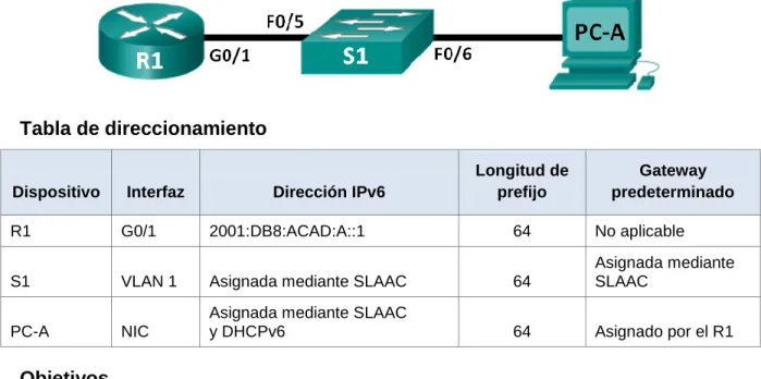
9.5.2.6 PACKET TRACER - CONFIGURING IPV6 ACLS
Topology
Addressing Table
Device Interface IPv6 Address/Prefix Default Gateway
Server3 NIC 2001:DB8:1:30::30/64 FE80::30
Objectives
Part 1: Configure, Apply, and Verify an IPv6 ACL
Part 2: Configure, Apply, and Verify a Second IPv6 ACL
Part 1:
Configure, Apply, and Verify an IPv6 ACL
Logs indicate that a computer on the 2001:DB8:1:11::0/64 network is repeatedly refreshing their web page causing a Denial-of-Service (DoS) attack against Server3. Until the client can be identified and cleaned, you must block HTTP and HTTPS access to that network with an access list.
Step 1: Configure an ACL that will block HTTP and HTTPS access.
Configure an ACL named BLOCK_HTTP on R1 with the following statements.
a. Block HTTP and HTTPS traffic from reaching Server3.
R1(config)# deny tcp any host 2001:DB8:1:30::30 eq www
b. Allow all other IPv6 traffic to pass.
Step 2: Apply the ACL to the correct interface.
Apply the ACL on the interface closest the source of the traffic to be blocked.
R1(config-if)# ipv6 traffic-filter BLOCK_HTTP in
Step 3: Verify the ACL implementation.
Verify the ACL is operating as intended by conducting the following tests:
Open the web browser of PC2 to http:// 2001:DB8:1:30::30 or https://2001:DB8:1:30::30.
The website should be blocked
Ping from PC2 to 2001:DB8:1:30::30. The ping should be successful.
Part 2:
Configure, Apply, and Verify a Second IPv6 ACL
The logs now indicate that your server is receiving pings from many different IPv6 addresses in a Distributed Denial of Service (DDoS) attack. You must filter ICMP ping requests to your server.
Step 1: Create an access list to block ICMP.
Configure an ACL named BLOCK_ICMP on R3 with the following statements:
a. Block all ICMP traffic from any hosts to any destination.
Step 2: Apply the ACL to the correct interface.
In this case, ICMP traffic can come from any source. To ensure that ICMP traffic is blocked regardless of its source or changes that occur to the network topology, apply the ACL closest to the destination.
Step 3: Verify that the proper access list functions.
a. Ping from PC2 to 2001:DB8:1:30::30. The ping should fail.
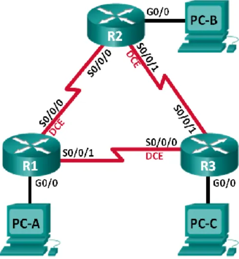
7.3.2.4 LAB - CONFIGURING BASIC RIPV2 AND RIPNG
Topología
Tabla de direccionamiento
Dispositivo Interfaz Dirección IP
Máscara de subred
Gateway predeterminado
R1 G0/1 172.30.10.1 255.255.255.0 N/A
S0/0/0 (DCE) 10.1.1.1 255.255.255.252 N/A
R2 G0/0 209.165.201.1 255.255.255.0 N/A
S0/0/0 10.1.1.2 255.255.255.252 N/A
S0/0/1 (DCE) 10.2.2.2 255.255.255.252 N/A
R3 G0/1 172.30.30.1 255.255.255.0 N/A
S0/0/1 10.2.2.1 255.255.255.252 N/A
S1 N/A VLAN 1 N/A N/A
S3 N/A VLAN 1 N/A N/A
PC-A NIC 172.30.10.3 255.255.255.0 172.30.10.1
PC-B NIC 209.165.201.2 255.255.255.0 209.165.201.1
Objetivos
Parte 1: armar la red y configurar los parámetros básicos de los
dispositivos
Parte 2: configurar y verificar el routing RIPv2
Configurar y verificar que se esté ejecutando RIPv2 en los routers.
Configurar una interfaz pasiva.
Examinar las tablas de routing.
Desactivar la sumarización automática.
Configurar una ruta predeterminada.
Verificar la conectividad de extremo a extremo.
Parte 3: configurar IPv6 en los dispositivos
Parte 4: configurar y verificar el routing RIPng
Configurar y verificar que se esté ejecutando RIPng en los routers.
Examinar las tablas de routing.
Configurar una ruta predeterminada.
Verificar la conectividad de extremo a extremo.
Información básica/situación
RIP versión 2 (RIPv2) se utiliza para enrutar direcciones IPv4 en redes
pequeñas. RIPv2 es un protocolo de routing vector distancia sin clase, según la
definición de RFC 1723. Debido a que RIPv2 es un protocolo de routing sin clase,
las máscaras de subred se incluyen en las actualizaciones de routing. De
manera predeterminada, RIPv2 resume automáticamente las redes en los
límites de redes principales. Cuando se deshabilita la sumarización automática,
RIPv2 ya no resume las redes a su dirección con clase en routers fronterizos.
RIP de última generación (RIPng) es un protocolo de routing vector distancia
para enrutar direcciones IPv6, según la definición de RFC 2080. RIPng se basa
en RIPv2 y tiene la misma distancia administrativa y limitación de 15 saltos.
En esta práctica de laboratorio, configurará la topología de la red con routing
RIPv2, deshabilitará la sumarización automática, propagará una ruta
predeterminada y usará comandos de CLI para ver y verificar la información de
routing RIP. Luego, configurará la topología de la red con direcciones IPv6,
configurará RIPng, propagará una ruta predeterminada y usará comandos de
CLI para ver y verificar la información de routing RIPng.
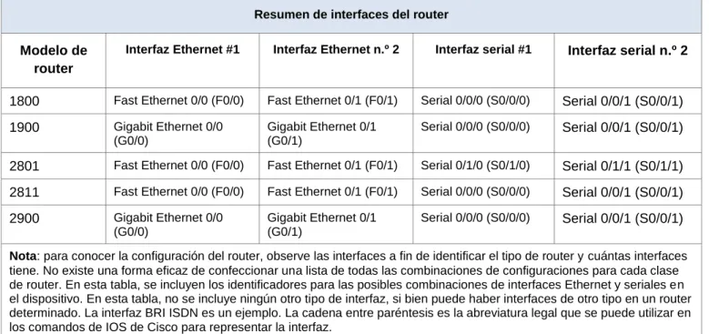
modelo y la versión de IOS de Cisco, los comandos disponibles y los resultados
que se obtienen pueden diferir de los que se muestran en las prácticas de
laboratorio. Consulte la tabla Resumen de interfaces del router que se encuentra
al final de la práctica de laboratorio para obtener los identificadores de interfaz
correctos.
Nota
: asegúrese de que los routers y los switches se hayan borrado y no tengan
configuraciones de inicio. Si no está seguro, consulte con el instructor.
Recursos necesarios
3 routers (Cisco 1941 con IOS de Cisco versión 15.2(4)M3, imagen
universal o similar)
2 switches (Cisco 2960 con IOS de Cisco versión 15.0(2), imagen
lanbasek9 o similar)
3 computadoras (Windows 7, Vista o XP con un programa de emulación de
terminal, como Tera Term)
Cables de consola para configurar los dispositivos con IOS de Cisco
mediante los puertos de consola
Cables Ethernet y seriales, como se muestra en la topología
Parte 1: armar la red y configurar los parámetros básicos de los dispositivos
En la parte 1, establecerá la topología de la red y configurará los parámetros
básicos.
Paso 1. realizar el cableado de red tal como se muestra en la topología.
Paso 2. inicializar y volver a cargar el router y el switch.
Paso 3. configurar los parámetros básicos para cada router y switch.
a. Desactive la búsqueda del DNS.
b. Configure los nombres de los dispositivos como se muestra en la topología.
c. Configurar la encriptación de contraseñas.
d. Asigne
class
como la contraseña del modo EXEC privilegiado.
e. Asigne
cisco
como la contraseña de consola y la contraseña de vty.
f. Configure un mensaje MOTD para advertir a los usuarios que se prohíbe el
acceso no autorizado.
g. Configure
logging synchronous
para la línea de consola.
h. Configure la dirección IP que se indica en la tabla de direccionamiento para
todas las interfaces.
j. Configure la frecuencia de reloj, si corresponde, para la interfaz serial DCE.
k. Copie la configuración en ejecución en la configuración de inicio.
Configuración del Router R1
Configuración del Router R3
Paso 4. configurar los equipos host.
Paso 5. Probar la conectividad.
En este momento, las computadoras no pueden hacerse ping entre sí. a. Cada estación de trabajo debe tener capacidad para hacer ping al router
b. Los routers deben poder hacerse ping entre sí. Verifique y resuelva los problemas, si es necesario
Parte 2: configurar y verificar el routing RIPv2
Paso 1. Configurar el enrutamiento RIPv2.
c. En el R1, configure RIPv2 como el protocolo de routing y anuncie las redes correspondientes.
R1# config t
R1(config)# router rip R1(config-router)# version 2
R1(config-router)# passive-interface g0/1 R1(config-router)# network 172.30.0.0 R1(config-router)# network 10.0.0.0
El comando passive-interface evita que las actualizaciones de routing se envíen a través de la interfaz especificada. Este proceso evita tráfico de routing
innecesario en la LAN. Sin embargo, la red a la que pertenece la interfaz
especificada aún se anuncia en las actualizaciones de routing enviadas por otras interfaces.
d. Configure RIPv2 en el R3 y utilice la instrucción network para agregar las redes apropiadas y evitar actualizaciones de routing en la interfaz LAN.
e. Configure RIPv2 en el R2. No anuncie la red 209.165.201.0.
Nota: no es necesario establecer la interfaz G0/0 como pasiva en el R2, porque la red asociada a esta interfaz no se está anunciando.
Paso 2. examinar el estado actual de la red.
a. Se pueden verificar los dos enlaces seriales rápidamente mediante el comando show ip interface brief en R2.
R2# show ip interface brief
Interface IP-Address OK? Method Status Protocol Embedded-Service-Engine0/0 unassigned YES unset administratively down down
GigabitEthernet0/0 209.165.201.1 YES manual up up
Serial0/0/1 10.2.2.2 YES manual up up
b. Verifique la conectividad entre las computadoras.
¿Es posible hacer ping de la PC-A a la PC-B? No ¿Por qué? No hay una ruta para la pc -B
¿Es posible hacer ping de la PC-A a la PC-C? No ¿Por qué? R1 y R3 no tiene rutas hacia la subnet específicas del Router remoto.
¿Es posible hacer ping de la PC-C a la PC-B? No ¿Por qué? PC – B no participa en rip, no existe una ruta.
¿Es posible hacer ping de la PC-C a la PC-A? No ¿Por qué? R1 y R3 no tienen rutas hacia la subnet especifica remota.
c. Verifique que RIPv2 se ejecute en los routers.
Puede usar los comandos debug ip rip, show ip protocols y show run para confirmar que RIPv2 esté en ejecución. A continuación, se muestra el resultado del comando show ip protocols para el R1.
R1# show ip protocols Routing Protocol is "rip"
Outgoing update filter list for all interfaces is not set Incoming update filter list for all interfaces is not set
Sending updates every 30 seconds, next due in 7 seconds Invalid after 180 seconds, hold down 180, flushed after 240 Redistributing: rip
Default version control: send version 2, receive 2
Interface Send Recv Triggered RIP Key-chain Serial0/0/0 2 2
Automatic network summarization is in effect Maximum path: 4
Routing for Networks: 10.0.0.0
172.30.0.0
GigabitEthernet0/1
Routing Information Sources:
Gateway Distance Last Update 10.1.1.2 120
Distance: (default is 120)
Al emitir el comando debug ip rip en el R2, ¿qué información se proporciona que confirma que RIPv2 está en ejecución?
Cuando haya terminado de observar los resultados de la depuración, emita el comando undebug all en la petición de entrada del modo EXEC privilegiado. Al emitir el comando show run en el R3, ¿qué información se proporciona que confirma que RIPv2 está en ejecución?
Building configuration...
Current configuration : 1167 bytes !
version 15.1
no service timestamps log datetime msec no service timestamps debug datetime msec no service password-encryption
hostname R3 !
enable secret 5 $1$mERr$9cTjUIEqNGurQiFU.ZeCi1 !
no ip cef
ipv6 unicast-routing !
no ipv6 cef !
license udi pid CISCO1941/K9 sn FTX15244L5G !
spanning-tree mode pvst !
interface GigabitEthernet0/0 no ip address
duplex auto speed auto shutdown !
interface GigabitEthernet0/1
ip address 172.30.30.1 255.255.255.252 duplex auto
speed auto
ipv6 address FE80::3 link-local
ipv6 address 2001:DB8:ACAD:C::3/64 ipv6 rip Test3 enable
!
interface Serial0/0/0 no ip address clock rate 2000000 shutdown
!
interface Serial0/0/1
ip address 10.2.2.1 255.255.255.252 ipv6 address FE80::3 link-local
ipv6 address 2001:DB8:ACAD:23::3/64 ipv6 rip Test3 enable
!
interface Vlan1 no ip address shutdown ! router rip version 2 network 10.0.0.0 network 172.30.0.0 !
ipv6 router rip Test3 !
ip flow-export version 9 !
banner motd ^C Acceso denegado ^C !
line con 0 password cisco login
!
line aux 0 !
line vty 0 4 password cisco login
! end
d. Examinar el sumarización automática de las rutas.
Las LAN conectadas al R1 y el R3 se componen de redes no contiguas. El R2 muestra dos rutas de igual costo a la red 172.30.0.0/16 en la tabla de routing. El R2 solo muestra la dirección de red principal con clase 172.30.0.0 y no muestra ninguna de las subredes de esta red.
R2# show ip route <Output Omitted>
10.0.0.0/8 is variably subnetted, 4 subnets, 2 masks C 10.1.1.0/30 is directly connected, Serial0/0/0 L 10.1.1.2/32 is directly connected, Serial0/0/0 C 10.2.2.0/30 is directly connected, Serial0/0/1 L 10.2.2.2/32 is directly connected, Serial0/0/1
R 172.30.0.0/16 [120/1] via 10.2.2.1, 00:00:23, Serial0/0/1 [120/1] via 10.1.1.1, 00:00:09, Serial0/0/0
El R1 solo muestra sus propias subredes para la red 172.30.0.0. El R1 no tiene ninguna ruta para las subredes 172.30.0.0 en el R3.
R1# show ip route <Output Omitted>
10.0.0.0/8 is variably subnetted, 3 subnets, 2 masks C 10.1.1.0/30 is directly connected, Serial0/0/0 L 10.1.1.1/32 is directly connected, Serial0/0/0
R 10.2.2.0/30 [120/1] via 10.1.1.2, 00:00:21, Serial0/0/0 172.30.0.0/16 is variably subnetted, 2 subnets, 2 masks C 172.30.10.0/24 is directly connected, GigabitEthernet0/1 L 172.30.10.1/32 is directly connected, GigabitEthernet0/1
El R3 solo muestra sus propias subredes para la red 172.30.0.0. El R3 no tiene ninguna ruta para las subredes 172.30.0.0 en el R1.
R3# show ip route <Output Omitted>
L 10.2.2.1/32 is directly connected, Serial0/0/1
R 10.1.1.0/30 [120/1] via 10.2.2.2, 00:00:23, Serial0/0/1 172.30.0.0/16 is variably subnetted, 2 subnets, 2 masks C 172.30.30.0/24 is directly connected, GigabitEthernet0/1 L 172.30.30.1/32 is directly connected, GigabitEthernet0/1
Utilice el comando debug ip rip en el R2 para determinar las rutas recibidas en las actualizaciones RIP del R3 e indíquelas a continuación.
El R3 no está envía ninguna de las subredes 172.30.0.0, solo la ruta resumida 172.30.0.0/16, incluida la máscara de subred. Por lo tanto, las tablas de routing del R1 y el R2 no muestran las subredes 172.30.0.0 en el R3.
Paso 3. Desactivar la sumarización automática.
e. El comando no auto-summary se utiliza para desactivar la sumarización
automática en RIPv2. Deshabilite la sumarización automática en todos los routers. Los routers ya no resumirán las rutas en los límites de las redes principales con clase. Aquí se muestra R1 como ejemplo.
R1(config)# router rip
f. Emita el comando clear ip route * para borrar la tabla de routing. R1(config-router)# end
R1# clear ip route *
g. Examinar las tablas de enrutamiento Recuerde que la convergencia de las tablas de routing demora un tiempo después de borrarlas.
Las subredes LAN conectadas al R1 y el R3 ahora deberían aparecer en las tres tablas de routing.
R2# show ip route <Output Omitted>
Gateway of last resort is not set
10.0.0.0/8 is variably subnetted, 4 subnets, 2 masks C 10.1.1.0/30 is directly connected, Serial0/0/0 L 10.1.1.2/32 is directly connected, Serial0/0/0 C 10.2.2.0/30 is directly connected, Serial0/0/1 L 10.2.2.2/32 is directly connected, Serial0/0/1
172.30.0.0/16 is variably subnetted, 3 subnets, 2 masks R 172.30.0.0/16 [120/1] via 10.2.2.1, 00:01:01, Serial0/0/1 [120/1] via 10.1.1.1, 00:01:15, Serial0/0/0
R1# show ip route <Output Omitted>
Gateway of last resort is not set
10.0.0.0/8 is variably subnetted, 3 subnets, 2 masks C 10.1.1.0/30 is directly connected, Serial0/0/0 L 10.1.1.1/32 is directly connected, Serial0/0/0
R 10.2.2.0/30 [120/1] via 10.1.1.2, 00:00:12, Serial0/0/0 172.30.0.0/16 is variably subnetted, 3 subnets, 2 masks C 172.30.10.0/24 is directly connected, GigabitEthernet0/1 L 172.30.10.1/32 is directly connected, GigabitEthernet0/1 R 172.30.30.0/24 [120/2] via 10.1.1.2, 00:00:12, Serial0/0/0
R3# show ip route <Output Omitted>
10.0.0.0/8 is variably subnetted, 3 subnets, 2 masks C 10.2.2.0/30 is directly connected, Serial0/0/1 L 10.2.2.1/32 is directly connected, Serial0/0/1
h. Utilice el comando debug ip rip en el R2 para examinar las actualizaciones RIP. R2# debug ip rip
Después de 60 segundos, emita el comando no debug ip rip.
¿Qué rutas que se reciben del R3 se encuentran en las actualizaciones RIP? 172.30.30.0/24 – 172.30.10.0/24
¿Se incluyen ahora las máscaras de las subredes en las actualizaciones de enrutamiento?
Si
Paso 4. Configure y redistribuya una ruta predeterminada para el acceso a Internet.
i. Desde el R2, cree una ruta estática a la red 0.0.0.0 0.0.0.0, con el comando ip route. Esto envía todo tráfico de dirección de destino desconocida a la interfaz G0/0 del R2 hacia la PC-B y simula Internet al establecer un gateway de último recurso en el router R2.
R2(config)# ip route 0.0.0.0 0.0.0.0 209.165.201.2
j. El R2 anunciará una ruta a los otros routers si se agrega el comando default-information originate a la configuración de RIP.
R2(config)# router rip
R2(config-router)# default-information originate
Paso 5. Verificar la configuración de enrutamiento.
k. Consulte la tabla de routing en el R1. R1# show ip route
<Output Omitted>
R* 0.0.0.0/0 [120/1] via 10.1.1.2, 00:00:13, Serial0/0/0 10.0.0.0/8 is variably subnetted, 3 subnets, 2 masks C 10.1.1.0/30 is directly connected, Serial0/0/0 L 10.1.1.1/32 is directly connected, Serial0/0/0
R 10.2.2.0/30 [120/1] via 10.1.1.2, 00:00:13, Serial0/0/0 172.30.0.0/16 is variably subnetted, 3 subnets, 2 masks C 172.30.10.0/24 is directly connected, GigabitEthernet0/1 L 172.30.10.1/32 is directly connected, GigabitEthernet0/1 R 172.30.30.0/24 [120/2] via 10.1.1.2, 00:00:13, Serial0/0/0
¿En qué forma se proporciona la ruta para el tráfico de Internet en la tabla de routing?
R2 tiene una ruta estática por defecto a través de la 209.165.201.2 que es directamente conectada a g0/0.
Paso 6. Verifique la conectividad.
a. Simule el envío de tráfico a Internet haciendo ping de la PC-A y la PC-C a 209.165.201.2.
¿Tuvieron éxito los pings? Si
b. Verifique que los hosts dentro de la red dividida en subredes tengan posibilidad de conexión entre sí haciendo ping entre la PC-A y la PC-C.
¿Tuvieron éxito los pings? Si
Parte 3: configurar IPv6 en los dispositivos
En la parte 3, configurará todas las interfaces con direcciones IPv6 y verificará la conectividad.
Tabla de direccionamiento
Dispositivo Interfaz Dirección IPv6/longitud de prefijo
Gateway predeterminado
R1 G0/1
2001:DB8:ACAD:A::1/64
FE80::1 link-local No aplicable
S0/0/0
2001:DB8:ACAD:12::1/64
FE80::1 link-local No aplicable
R2 G0/0
2001:DB8:ACAD:B::2/64
FE80::2 link-local No aplicable
S0/0/0
2001:DB8:ACAD:12::2/64
FE80::2 link-local No aplicable
S0/0/1
2001:DB8:ACAD:23::2/64
FE80::2 link-local No aplicable
R3 G0/1
2001:DB8:ACAD:C::3/64
FE80::3 link-local No aplicable
S0/0/1
2001:DB8:ACAD:23::3/64
FE80::3 link-local No aplicable
PC-A NIC 2001:DB8:ACAD:A::A/64 FE80::1
PC-B NIC 2001:DB8:ACAD:B::B/64 FE80::2
Paso 7. configurar los equipos host.
Consulte la tabla de direccionamiento para obtener información de direcciones de los equipos host.
Paso 7. configurar IPv6 en los routers.
Nota: la asignación de una dirección IPv6 además de una dirección IPv4 en una interfaz se conoce como “dual-stacking” (o apilamiento doble). Esto se debe a que las pilas de protocolos IPv4 e IPv6 están activas.
a. Para cada interfaz del router, asigne la dirección global y la dirección link local de la tabla de direccionamiento.
d. Introduzca el comando apropiado para verificar las direcciones IPv6 y el estado de enlace. Escriba el comando en el espacio que se incluye a continuación.
Show ipv6 interface brief
f. Los routers deben poder hacerse ping entre sí. Verifique y resuelva los problemas, si es necesario.
Parte 4: configurar y verificar el routing RIPng
En la parte 4, configurará el routing RIPng en todos los routers, verificará que las tablas de routing estén correctamente actualizadas, configurará y distribuirá una ruta predeterminada, y verificará la conectividad de extremo a extremo.
Paso 8. configurar el routing RIPng.
Con IPv6, es común tener varias direcciones IPv6 configuradas en una interfaz. La instrucción network se eliminó en RIPng. En cambio, el routing RIPng se habilita en el nivel de la interfaz y se identifica por un nombre de proceso pertinente en el nivel local, ya que se pueden crear varios procesos con RIPng.
g. Emita el comando ipv6 rip Test1 enable para cada interfaz en el R1 que
participará en el routing RIPng, donde Test1 es el nombre de proceso pertinente en el nivel local.
R1(config)# interface g0/1
R1(config)# interface s0/0/0 R1(config)# ipv6 rip Test1 enable
h. Configure RIPng para las interfaces seriales en el R2, con Test2 como el nombre de proceso. No lo configure para la interfaz G0/0
i. Configure RIPng para cada interfaz en el R3, con Test3 como el nombre de proceso.
j. Verifique que RIPng se esté ejecutando en los routers.
Los comandos show ipv6 protocols, show run, show ipv6 rip database y show ipv6 rip nombre de proceso se pueden usar para confirmar que se esté
ejecutando RIPng En el R1, emita el comando show ipv6 protocols. R1# show ipv6 protocols
IPv6 Routing Protocol is "connected" IPv6 Routing Protocol is "ND"
IPv6 Routing Protocol is "rip Test1" Interfaces:
Serial0/0/0
GigabitEthernet0/1 Redistribution: None
¿En qué forma se indica RIPng en el resultado? Ripng está listado por el nombre del proceso
k. Emita el comando show ipv6 rip Test1. R1# show ipv6 rip Test1
RIP process "Test1", port 521, multicast-group FF02::9, pid 314 Administrative distance is 120. Maximum paths is 16
Holddown lasts 0 seconds, garbage collect after 120 Split horizon is on; poison reverse is off
Default routes are not generated Periodic updates 1, trigger updates 0 Full Advertisement 0, Delayed Events 0 Interfaces:
GigabitEthernet0/1 Serial0/0/0
Redistribution: None
¿Cuáles son las similitudes entre RIPv2 y RIPng?
RIPv2 y RIPng ienen una distancia administrativa de 120, usan el conteo de saltos como la métrica y envían actualizaciones cada 30 segundos.
En el R1, ¿cuántas rutas se descubrieron mediante RIPng? 2 En el R2, ¿cuántas rutas se descubrieron mediante RIPng? 2 En el R3, ¿cuántas rutas se descubrieron mediante RIPng? 2 m. Verifique la conectividad entre las computadoras.
¿Es posible hacer ping de la PC-A a la PC-B? No ¿Es posible hacer ping de la PC-A a la PC-C? Si ¿Es posible hacer ping de la PC-C a la PC-B? Si ¿Es posible hacer ping de la PC-C a la PC-A? Si
¿Por qué algunos pings tuvieron éxito y otros no? Porque algunas veces no hay una ruta notificada para el pc B
Paso 9. configurar y volver a distribuir una ruta predeterminada.
a. Desde el R2, cree una ruta estática predeterminada a la red:: 0/64 con el comando ipv6 route y la dirección IP de la interfaz de salida G0/0. Esto reenvía todo tráfico de dirección de destino desconocida a la interfaz G0/0 del R2 hacia la PC-B y simula Internet. Escriba el comando que utilizó en el espacio a continuación.
b. Las rutas estáticas se pueden incluir en las actualizaciones RIPng mediante el comando ipv6 rip nombre de proceso default-information originate en el modo de configuración de interfaz. Configure los enlaces seriales en el R2 para enviar la ruta predeterminada en actualizaciones RIPng.
R2(config)# int s0/0/0
R2(config-rtr)# ipv6 rip Test2 default-information originate R2(config)# int s0/0/1
R2(config-rtr)# ipv6 rip Test2 default-information originate
Paso 10. Verificar la configuración de enrutamiento.
IPv6 Routing Table - 10 entries
Codes: C - Connected, L - Local, S - Static, R - RIP, B - BGP U - Per-user Static route, M - MIPv6
I1 - ISIS L1, I2 - ISIS L2, IA - ISIS interarea, IS - ISIS summary
O - OSPF intra, OI - OSPF inter, OE1 - OSPF ext 1, OE2 - OSPF ext 2 ON1 - OSPF NSSA ext 1, ON2 - OSPF NSSA ext 2
D - EIGRP, EX - EIGRP external S ::/64 [1/0]
via 2001:DB8:ACAD:B::B R 2001:DB8:ACAD:A::/64 [120/2] via FE80::1, Serial0/0/0
C 2001:DB8:ACAD:B::/64 [0/0] via ::, GigabitEthernet0/1 L 2001:DB8:ACAD:B::2/128 [0/0] via ::, GigabitEthernet0/1 R 2001:DB8:ACAD:C::/64 [120/2] via FE80::3, Serial0/0/1
C 2001:DB8:ACAD:12::/64 [0/0] via ::, Serial0/0/0
L 2001:DB8:ACAD:12::2/128 [0/0] via ::, Serial0/0/0
C 2001:DB8:ACAD:23::/64 [0/0] via ::, Serial0/0/1
L 2001:DB8:ACAD:23::2/128 [0/0] via ::, Serial0/0/1
L FF00::/8 [0/0] via ::, Null0
¿Cómo se puede saber, a partir de la tabla de routing, que el R2 tiene una ruta para el tráfico de Internet?
¿Cómo se proporciona la ruta para el tráfico de Internet en sus tablas de enrutamiento?
La tabla de ruteo muestra distribuida ripng gracias a rip con una métrica de 2.
Paso 11. Verifique la conectividad.
Simule el envío de tráfico a Internet haciendo ping de la PC-A y la PC-C a 2001:DB8:ACAD:B::B/64.
¿Tuvieron éxito los pings? Si
Reflexión
1. ¿Por qué desactivaría la sumarización automática para RIPv2? Sería bueno para que los Router no sumaricen las rutas hacia la clase mayor, y asi poder conectividad entre redes discontinuas.
2. En ambas situaciones, ¿en qué forma descubrieron la ruta a Internet el R1 y el R3? Las aprendieron de las actualizaciones de rip recibidas desde el R2 donde fue configurada la ruta por defecto
3. ¿En qué se diferencian la configuración de RIPv2 y la de RIPng? • En RIPv2 admite actualizaciones RiPv1, RIpng no
• En RIPv2 se puede colocar etiquetas a las rutas
• RIPv2 codifica el siguiente salto en cada entrada de la ruta, mientras que con RIPng se requiere de una codificación especifica.
• RIPv2 determina las redes sumarizadas en la interfaz
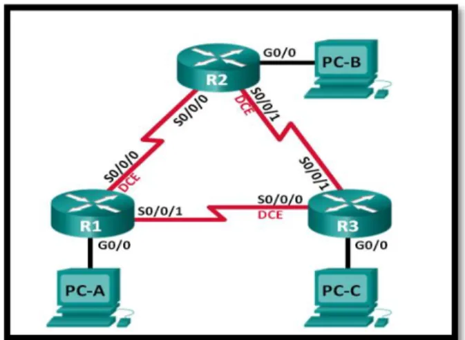
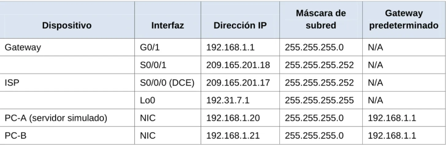
8.2.4.5 LAB - CONFIGURING BASIC SINGLE-AREA OSPFV2.
Topología
Tabla de direccionamiento
Dispositivo Interfaz Dirección IP Máscara de subred
Gateway predeterminado
R1 G0/0 192.168.1.1 255.255.255.0 N/A
S0/0/0 (DCE) 192.168.12.1 255.255.255.252 N/A
S0/0/1 192.168.13.1 255.255.255.252 N/A
R2 G0/0 192.168.2.1 255.255.255.0 N/A
S0/0/0 192.168.12.2 255.255.255.252 N/A
S0/0/1 (DCE) 192.168.23.1 255.255.255.252 N/A
R3 G0/0 192.168.3.1 255.255.255.0 N/A
S0/0/0 (DCE) 192.168.13.2 255.255.255.252 N/A
S0/0/1 192.168.23.2 255.255.255.252 N/A
PC-A NIC 192.168.1.3 255.255.255.0 192.168.1.1
PC-B NIC 192.168.2.3 255.255.255.0 192.168.2.1
Objetivos
Parte 1: armar la red y configurar los parámetros básicos de los dispositivos
Parte 2: configurar y verificar el routing OSPF
Parte 3: cambiar las asignaciones de ID del router
Parte 4: configurar interfaces OSPF pasivas
Parte 5: cambiar las métricas de OSPF
Información básica/situación
El protocolo OSPF (Open Shortest Path First) es un protocolo de routing de estado de enlace para las redes IP. Se definió OSPFv2 para redes IPv4, y OSPFv3 para redes IPv6. OSPF detecta cambios en la topología, como fallas de enlace, y converge en una nueva estructura de routing sin bucles muy rápidamente. Computa cada ruta con el algoritmo de Dijkstra, un algoritmo SPF (Shortest Path First).
En esta práctica de laboratorio, configurará la topología de la red con routing OSPFv2, cambiará las asignaciones de ID de router, configurará interfaces pasivas, ajustará las métricas de OSPF y utilizará varios comandos de CLI para ver y verificar la información de routing OSPF.
Nota: los routers que se utilizan en las prácticas de laboratorio de CCNA son routers de servicios integrados (ISR) Cisco 1941 con IOS de Cisco versión 15.2(4)M3 (imagen universalk9). Pueden utilizarse otros routers y otras versiones del IOS de Cisco. Según el modelo y la versión de IOS de Cisco, los comandos disponibles y los resultados que se obtienen pueden diferir de los que se muestran en las prácticas de laboratorio. Consulte la tabla Resumen de interfaces del router que se encuentra al final de esta práctica de laboratorio para obtener los identificadores de interfaz correctos.
Nota: asegúrese de que los routers se hayan borrado y no tengan configuraciones de inicio. Si no está seguro, consulte con el instructor.
Recursos necesarios
3 routers (Cisco 1941 con IOS de Cisco versión 15.2(4)M3, imagen universal o similar)
3 computadoras (Windows 7, Vista o XP con un programa de emulación de terminal, como Tera Term)
Cables de consola para configurar los dispositivos con IOS de Cisco mediante los puertos de consola
Cables Ethernet y seriales, como se muestra en la topología
Parte 1. armar la red y configurar los parámetros básicos de los dispositivos
Paso 1. realizar el cableado de red tal como se muestra en la topología.
Paso 2. inicializar y volver a cargar los routers según sea necesario.
Paso 3. configurar los parámetros básicos para cada router.
a. Desactive la búsqueda del DNS.
b. Configure el nombre del dispositivo como se muestra en la topología. c. Asigne class como la contraseña del modo EXEC privilegiado. d. Asigne cisco como la contraseña de consola y la contraseña de vty.
e. Configure un aviso de mensaje del día (MOTD) para advertir a los usuarios que el acceso no autorizado está prohibido.
f. Configure logging synchronous para la línea de consola.
g. Configure la dirección IP que se indica en la tabla de direccionamiento para todas las interfaces.
h. Establezca la frecuencia de reloj para todas las interfaces seriales DCE en 128000.
i. Copie la configuración en ejecución en la configuración de inicio
Paso 4. configurar los equipos host.
Paso 5. Probar la conectividad.
Los routers deben poder hacerse ping entre sí, y cada computadora debe poder hacer ping a su gateway predeterminado. Las computadoras no pueden hacer ping a otras computadoras hasta que no se haya configurado el routing OSPF. Verifique y resuelva los problemas, si es necesario.
Parte 2. Configurar y verificar el enrutamiento OSPF
En la parte 2, configurará el routing OSPFv2 en todos los routers de la red y, luego, verificará que las tablas de routing se hayan actualizado correctamente. Después de verificar OSPF, configurará la autenticación de OSPF en los enlaces para mayor seguridad.
Paso 1. Configure el protocolo OSPF en R1.
a. Use el comando router ospf en el modo de configuración global para habilitar OSPF en el R1.
R1(config)# router ospf 1
Nota: la ID del proceso OSPF se mantiene localmente y no tiene sentido para los otros routers de la red.
b. Configure las instrucciones network para las redes en el R1. Utilice la ID de área 0.
R1(config-router)# network 192.168.13.0 0.0.0.3 area 0
Paso 2. Configure OSPF en el R2 y el R3.
Use el comando router ospf y agregue las instrucciones network para las redes en el R2 y el R3. Cuando el routing OSPF está configurado en el R2 y el R3, se muestran mensajes de adyacencia de vecino en el R1.
R1#
00:22:29: %OSPF-5-ADJCHG: Process 1, Nbr 192.168.23.1 on Serial0/0/0 from LOADING to FULL, Loading Done
R1#
00:23:14: %OSPF-5-ADJCHG: Process 1, Nbr 192.168.23.2 on Serial0/0/1 from LOADING to FULL, Loading Done
R1#
Paso 3. verificar los vecinos OSPF y la información de routing.
a. Emita el comando show ip ospf neighbor para verificar que cada router indique a los demás routers en la red como vecinos.
R1# show ip ospf neighbor
Neighbor ID Pri State Dead Time Address Interface 192.168.23.2 0 FULL/ - 00:00:33 192.168.13.2 Serial0/0/1 192.168.23.1 0 FULL/ - 00:00:30 192.168.12.2 Serial0/0/0
b. Emita el comando show ip route para verificar que todas las redes aparezcan en la tabla de routing de todos los routers.
R1# show ip route
Codes: L - local, C - connected, S - static, R - RIP, M - mobile, B - BGP D - EIGRP, EX - EIGRP external, O - OSPF, IA - OSPF inter area N1 - OSPF NSSA external type 1, N2 - OSPF NSSA external type 2 E1 - OSPF external type 1, E2 - OSPF external type 2, E - EGP i - IS-IS, L1 - IS-IS level-1, L2 - IS-IS level-2, ia - IS-IS inter area * - candidate default, U - per-user static route, o - ODR
P - periodic downloaded static route
192.168.1.0/24 is variably subnetted, 2 subnets, 2 masks C 192.168.1.0/24 is directly connected, GigabitEthernet0/0 L 192.168.1.1/32 is directly connected, GigabitEthernet0/0 O 192.168.2.0/24 [110/65] via 192.168.12.2, 00:32:33, Serial0/0/0 O 192.168.3.0/24 [110/65] via 192.168.13.2, 00:31:48, Serial0/0/1 192.168.12.0/24 is variably subnetted, 2 subnets, 2 masks C 192.168.12.0/30 is directly connected, Serial0/0/0 L 192.168.12.1/32 is directly connected, Serial0/0/0 192.168.13.0/24 is variably subnetted, 2 subnets, 2 masks C 192.168.13.0/30 is directly connected, Serial0/0/1 L 192.168.13.1/32 is directly connected, Serial0/0/1 192.168.23.0/30 is subnetted, 1 subnets
O 192.168.23.0/30 [110/128] via 192.168.12.2, 00:31:38, Serial0/0/0 [110/128] via 192.168.13.2, 00:31:38, Serial0/0/1
¿Qué comando utilizaría para ver solamente las rutas OSPF en la tabla de routing? Show ip route ospf
Paso 4. verificar la configuración del protocolo OSPF.
El comando show ip protocols es una manera rápida de verificar información fundamental de configuración de OSPF. Esta información incluye la ID del proceso OSPF, la ID del router, las redes que anuncia el router, los vecinos de los que el router recibe actualizaciones y la distancia administrativa predeterminada, que para OSPF es 110.
R1# show ip protocols
Routing Protocol is "ospf 1"
Outgoing update filter list for all interfaces is not set Incoming update filter list for all interfaces is not set Router ID 192.168.13.1
Number of areas in this router is 1. 1 normal 0 stub 0 nssa Maximum path: 4
Routing for Networks:
192.168.1.0 0.0.0.255 area 0 192.168.12.0 0.0.0.3 area 0 192.168.13.0 0.0.0.3 area 0 Routing Information Sources:
Gateway Distance Last Update 192.168.23.2 110 00:19:16 192.168.23.1 110 00:20:03 Distance: (default is 110)
Paso 5. verificar la información del proceso OSPF.
Use el comando show ip ospf para examinar la ID del proceso OSPF y la ID del router. Este comando muestra información de área OSPF y la última vez que se calculó el algoritmo SPF.
R1# show ip ospf
Routing Process "ospf 1" with ID 192.168.13.1
Start time: 00:20:23.260, Time elapsed: 00:25:08.296 Supports only single TOS(TOS0) routes
Supports opaque LSA
Supports Link-local Signaling (LLS) Supports area transit capability
Event-log enabled, Maximum number of events: 1000, Mode: cyclic Router is not originating router-LSAs with maximum metric
Initial SPF schedule delay 5000 msecs
Minimum hold time between two consecutive SPFs 10000 msecs Maximum wait time between two consecutive SPFs 10000 msecs Incremental-SPF disabled
Minimum LSA interval 5 secs Minimum LSA arrival 1000 msecs LSA group pacing timer 240 secs Interface flood pacing timer 33 msecs Retransmission pacing timer 66 msecs
Number of external LSA 0. Checksum Sum 0x000000 Number of opaque AS LSA 0. Checksum Sum 0x000000 Number of DCbitless external and opaque AS LSA 0 Number of DoNotAge external and opaque AS LSA 0 Number of areas in this router is 1. 1 normal 0 stub 0 nssa Number of areas transit capable is 0
External flood list length 0
IETF NSF helper support enabled Cisco NSF helper support enabled Reference bandwidth unit is 100 mbps Area BACKBONE(0)
Number of interfaces in this area is 3 Area has no authentication
SPF algorithm last executed 00:22:53.756 ago SPF algorithm executed 7 times
Area ranges are
Number of LSA 3. Checksum Sum 0x019A61
Number of opaque link LSA 0. Checksum Sum 0x000000 Number of DCbitless LSA 0
Paso 6. verificar la configuración de la interfaz OSPF.
a. Emita el comando show ip ospf interface brief para ver un resumen de las interfaces con OSPF habilitado.
R1# show ip ospf interface brief
Interface PID Area IP Address/Mask Cost State Nbrs F/C Se0/0/1 1 0 192.168.13.1/30 64 P2P 1/1
Se0/0/0 1 0 192.168.12.1/30 64 P2P 1/1 Gi0/0 1 0 192.168.1.1/24 1 DR 0/0
b. Para obtener una lista detallada de todas las interfaces con OSPF habilitado, emita el comando show ip ospf interface.
R1# show ip ospf interface
Serial0/0/1 is up, line protocol is up
Internet Address 192.168.13.1/30, Area 0, Attached via Network Statement Process ID 1, Router ID 192.168.13.1, Network Type POINT_TO_POINT, Cost: 64
Topology-MTID Cost Disabled Shutdown Topology Name 0 64 no no Base
Transmit Delay is 1 sec, State POINT_TO_POINT
Timer intervals configured, Hello 10, Dead 40, Wait 40, Retransmit 5 oob-resync timeout 40
Hello due in 00:00:01
IETF NSF helper support enabled Index 3/3, flood queue length 0 Next 0x0(0)/0x0(0)
Last flood scan length is 1, maximum is 1
Last flood scan time is 0 msec, maximum is 0 msec Neighbor Count is 1, Adjacent neighbor count is 1 Adjacent with neighbor 192.168.23.2
Suppress hello for 0 neighbor(s) Serial0/0/0 is up, line protocol is up
Internet Address 192.168.12.1/30, Area 0, Attached via Network Statement Process ID 1, Router ID 192.168.13.1, Network Type POINT_TO_POINT, Cost: 64
Topology-MTID Cost Disabled Shutdown Topology Name 0 64 no no Base
Transmit Delay is 1 sec, State POINT_TO_POINT
Timer intervals configured, Hello 10, Dead 40, Wait 40, Retransmit 5 oob-resync timeout 40
Hello due in 00:00:03
Supports Link-local Signaling (LLS) Cisco NSF helper support enabled IETF NSF helper support enabled Index 2/2, flood queue length 0 Next 0x0(0)/0x0(0)
Last flood scan length is 1, maximum is 1
Last flood scan time is 0 msec, maximum is 0 msec Neighbor Count is 1, Adjacent neighbor count is 1 Adjacent with neighbor 192.168.23.1
Suppress hello for 0 neighbor(s)
GigabitEthernet0/0 is up, line protocol is up
Internet Address 192.168.1.1/24, Area 0, Attached via Network Statement Process ID 1, Router ID 192.168.13.1, Network Type BROADCAST, Cost: 1 Topology-MTID Cost Disabled Shutdown Topology Name
0 1 no no Base Transmit Delay is 1 sec, State DR, Priority 1
Designated Router (ID) 192.168.13.1, Interface address 192.168.1.1 No backup designated router on this network
Timer intervals configured, Hello 10, Dead 40, Wait 40, Retransmit 5 oob-resync timeout 40
Hello due in 00:00:01
IETF NSF helper support enabled Index 1/1, flood queue length 0 Next 0x0(0)/0x0(0)
Last flood scan length is 0, maximum is 0
Last flood scan time is 0 msec, maximum is 0 msec Neighbor Count is 0, Adjacent neighbor count is 0 Suppress hello for 0 neighbor(s)
Paso 7. Verificar la conectividad de extremo a extremo.
Se debería poder hacer ping entre todas las computadoras de la topología. Verifique y resuelva los problemas, si es necesario.
Nota: puede ser necesario desactivar el firewall de las computadoras para hacer ping entre ellas.
Parte 3. cambiar las asignaciones de ID del router
El ID del router OSPF se utiliza para identificar de forma única el router en el dominio de enrutamiento OSPF. Los routers Cisco derivan la ID del router en una de estas tres formas y con la siguiente prioridad:
1) Dirección IP configurada con el comando de OSPF router-id, si la hubiera 2) Dirección IP más alta de cualquiera de las direcciones de loopback del router,
si la hubiera
Dado que no se ha configurado ningún ID o interfaz de loopback en los tres routers, el ID de router para cada ruta se determina según la dirección IP más alta de cualquier interfaz activa.
En la parte 3, cambiará la asignación de ID del router OSPF con direcciones de loopback. También usará el comando router-id para cambiar la ID del router.
Paso 1. Cambie las ID de router con direcciones de loopback.
a. Asigne una dirección IP al loopback 0 en el R1. R1(config)# interface lo0
R1(config-if)# ip address 1.1.1.1 255.255.255.255 R1(config-if)# end
b. Asigne direcciones IP al loopback 0 en el R2 y el R3. Utilice la dirección IP 2.2.2.2/32 para el R2 y 3.3.3.3/32 para el R3.
c. Guarde la configuración en ejecución en la configuración de inicio de todos los routers.
d. Debe volver a cargar los routers para restablecer la ID del router a la dirección de loopback. Emita el comando reload en los tres routers. Presione Enter para confirmar la recarga.
e. Una vez que se haya completado el proceso de recarga del router, emita el comando show ip protocols para ver la nueva ID del router.
R1# show ip protocols
*** IP Routing is NSF aware ***
Routing Protocol is "ospf 1"
Router ID 1.1.1.1
Number of areas in this router is 1. 1 normal 0 stub 0 nssa Maximum path: 4
Routing for Networks:
192.168.1.0 0.0.0.255 area 0 192.168.12.0 0.0.0.3 area 0 192.168.13.0 0.0.0.3 area 0 Routing Information Sources:
Gateway Distance Last Update 3.3.3.3 110 00:01:00
2.2.2.2 110 00:01:14 Distance: (default is 110)
f. Emita el comando show ip ospf neighbor para mostrar los cambios de ID de router de los routers vecinos.
R1# show ip ospf neighbor
Paso 2. cambiar la ID del router R1 con el comando router-id.
El método de preferencia para establecer la ID del router es mediante el comando router-id.
a. Emita el comando router-id 11.11.11.11 en el R1 para reasignar la ID del router. Observe el mensaje informativo que aparece al emitir el comando router-id.
R1(config)# router ospf 1
R1(config-router)# router-id 11.11.11.11
Reload or use "clear ip ospf process" command, for this to take effect R1(config)# end
b. Recibirá un mensaje informativo en el que se le indique que debe volver a cargar el router o usar el comando clear ip ospf process para que se aplique el cambio. Emita el comando clear ip ospf process en los tres routers. Escriba yes (sí) como respuesta al mensaje de verificación de restablecimiento y presione Enter.
c. Establezca la ID del router R2 22.22.22.22 y la ID del router R3 33.33.33.33. Luego, use el comando clear ip ospf process para restablecer el proceso de routing de OSPF.
R2(config)#router ospf 1
R2(config-router)#router-id 22.22.22.22
R2(config-router)#Reload or use "clear ip ospf process" command, for this to take effect
R3(config)#router ospf 1
R3(config-router)#router-id 33.33.33.33
R3(config-router)#Reload or use "clear ip ospf process" command, for this to take effect
d. Emita el comando show ip protocols para verificar que la ID del router R1 haya cambiado.
R1# show ip protocols
*** IP Routing is NSF aware ***
Routing Protocol is "ospf 1"
Number of areas in this router is 1. 1 normal 0 stub 0 nssa Maximum path: 4
Routing for Networks:
192.168.1.0 0.0.0.255 area 0 192.168.12.0 0.0.0.3 area 0 192.168.13.0 0.0.0.3 area 0 Passive Interface(s):
GigabitEthernet0/1
Routing Information Sources:
Gateway Distance Last Update 33.33.33.33 110 00:00:19 22.22.22.22 110 00:00:31 3.3.3.3 110 00:00:41 2.2.2.2 110 00:00:41 Distance: (default is 110)
e. Emita el comando show ip ospf neighbor en el R1 para verificar que se muestren las nuevas ID de los routers R2 y R3.
R1# show ip ospf neighbor
Parte 4. configurar las interfaces pasivas de OSPF
El comando passive-interface evita que se envíen actualizaciones de routing a través de la interfaz de router especificada. Esto se hace comúnmente para reducir el tráfico en las redes LAN, ya que no necesitan recibir comunicaciones de protocolo de routing dinámico. En la parte 4, utilizará el comando passive-interface para configurar una única interfaz como pasiva. También configurará OSPF para que todas las interfaces del router sean pasivas de manera predeterminada y, luego, habilitará anuncios de routing OSPF en interfaces seleccionadas.
Paso 1. configurar una interfaz pasiva.
a. Emita el comando show ip ospf interface g0/0 en el R1. Observe el temporizador que indica cuándo se espera el siguiente paquete de saludo. Los paquetes de saludo se envían cada 10 segundos y se utilizan entre los routers OSPF para verificar que sus vecinos estén activos.
R1# show ip ospf interface g0/0
GigabitEthernet0/0 is up, line protocol is up
Internet Address 192.168.1.1/24, Area 0, Attached via Network Statement Process ID 1, Router ID 11.11.11.11, Network Type BROADCAST, Cost: 1 Topology-MTID Cost Disabled Shutdown Topology Name
0 1 no no Base Transmit Delay is 1 sec, State DR, Priority 1
Designated Router (ID) 11.11.11.11, Interface address 192.168.1.1 No backup designated router on this network
Timer intervals configured, Hello 10, Dead 40, Wait 40, Retransmit 5 oob-resync timeout 40
Hello due in 00:00:02
Supports Link-local Signaling (LLS) Cisco NSF helper support enabled IETF NSF helper support enabled Index 1/1, flood queue length 0 Next 0x0(0)/0x0(0)
Last flood scan length is 0, maximum is 0
b. Emita el comando passive-interface para cambiar la interfaz G0/0 en el R1 a pasiva.
R1(config)# router ospf 1
R1(config-router)# passive-interface g0/0
c. Vuelva a emitir el comando show ip ospf interface g0/0 para verificar que la interfaz G0/0 ahora sea pasiva.
R1# show ip ospf interface g0/0
GigabitEthernet0/0 is up, line protocol is up
Internet Address 192.168.1.1/24, Area 0, Attached via Network Statement Process ID 1, Router ID 11.11.11.11, Network Type BROADCAST, Cost: 1 Topology-MTID Cost Disabled Shutdown Topology Name
0 1 no no Base Transmit Delay is 1 sec, State DR, Priority 1
Designated Router (ID) 11.11.11.11, Interface address 192.168.1.1 No backup designated router on this network
Timer intervals configured, Hello 10, Dead 40, Wait 40, Retransmit 5 oob-resync timeout 40
Last flood scan length is 0, maximum is 0
Last flood scan time is 0 msec, maximum is 0 msec Neighbor Count is 0, Adjacent neighbor count is 0 Suppress hello for 0 neighbor(s)
d. Emita el comando show ip route en el R2 y el R3 para verificar que todavía haya disponible una ruta a la red 192.168.1.0/24.
R2# show ip route
Codes: L - local, C - connected, S - static, R - RIP, M - mobile, B - BGP D - EIGRP, EX - EIGRP external, O - OSPF, IA - OSPF inter area N1 - OSPF NSSA external type 1, N2 - OSPF NSSA external type 2 E1 - OSPF external type 1, E2 - OSPF external type 2
i - IS-IS, su - IS-IS summary, L1 - IS-IS level-1, L2 - IS-IS level-2 ia - IS-IS inter area, * - candidate default, U - per-user static route o - ODR, P - periodic downloaded static route, H - NHRP, l - LISP + - replicated route, % - next hop override
Gateway of last resort is not set
2.0.0.0/32 is subnetted, 1 subnets
C 2.2.2.2 is directly connected, Loopback0
O 192.168.1.0/24 [110/65] via 192.168.12.1, 00:58:32, Serial0/0/0 192.168.2.0/24 is variably subnetted, 2 subnets, 2 masks
192.168.13.0/30 is subnetted, 1 subnets
O 192.168.13.0 [110/128] via 192.168.23.2, 00:58:19, Serial0/0/1 [110/128] via 192.168.12.1, 00:58:32, Serial0/0/0 192.168.23.0/24 is variably subnetted, 2 subnets, 2 masks C 192.168.23.0/30 is directly connected, Serial0/0/1 L 192.168.23.1/32 is directly connected, Serial0/0/1
R3#show ip route
Codes: L - local, C - connected, S - static, R - RIP, M - mobile, B - BGP D - EIGRP, EX - EIGRP external, O - OSPF, IA - OSPF inter area N1 - OSPF NSSA external type 1, N2 - OSPF NSSA external type 2 E1 - OSPF external type 1, E2 - OSPF external type 2, E - EGP i - IS-IS, L1 - IS-IS level-1, L2 - IS-IS level-2, ia - IS-IS inter area * - candidate default, U - per-user static route, o - ODR
P - periodic downloaded static route
Gateway of last resort is not set
3.0.0.0/32 is subnetted, 1 subnets
C 3.3.3.3/32 is directly connected, Loopback0
O 192.168.1.0/24 [110/65] via 192.168.13.1, 00:07:41, Serial0/0/0 O 192.168.2.0/24 [110/65] via 192.168.23.1, 00:08:36, Serial0/0/1 192.168.3.0/24 is variably subnetted, 2 subnets, 2 masks
C 192.168.3.0/24 is directly connected, GigabitEthernet0/0 L 192.168.3.1/32 is directly connected, GigabitEthernet0/0 192.168.12.0/30 is subnetted, 1 subnets
O 192.168.12.0/30 [110/128] via 192.168.23.1, 00:07:41, Serial0/0/1 [110/128] via 192.168.13.1, 00:07:41, Serial0/0/0
L 192.168.13.2/32 is directly connected, Serial0/0/0 192.168.23.0/24 is variably subnetted, 2 subnets, 2 masks C 192.168.23.0/30 is directly connected, Serial0/0/1 L 192.168.23.2/32 is directly connected, Serial0/0/1 R3#
Paso 2. establecer la interfaz pasiva como la interfaz predeterminada en un router.
a. Emita el comando show ip ospf neighbor en el R1 para verificar que el R2 aparezca como un vecino OSPF.
R1# show ip ospf neighbor
Neighbor ID Pri State Dead Time Address Interface 33.33.33.33 0 FULL/ - 00:00:31 192.168.13.2 Serial0/0/1 22.22.22.22 0 FULL/ - 00:00:32 192.168.12.2 Serial0/0/0
b. Emita el comando passive-interface default en el R2 para establecer todas las interfaces OSPF como pasivas de manera predeterminada.
R2(config)# router ospf 1
R2(config-router)# passive-interface default R2(config-router)#