DIPLOMADO DE PROFUNDIZACION CISCO PRUEBA DE HABILIDADES PRÁCTICAS CCNP
JHON ALEJANDRO SANCHEZ OSORIO
UNIVERSIDAD NACIONAL ABIERTA Y A DISTANCIA - UNAD
ESCUELA DE CIENCIAS BÁSICAS, TECNOLOGÍA E INGENIERÍA - ECBTI INGENIERIA ELECTRÓNICA
DIPLOMADO DE PROFUNDIZACION CISCO PRUEBA DE HABILIDADES PRÁCTICAS CCNP
JHON ALEJANDRO SANCHEZ OSORIO
Diplomado de opción de grado presentado para optar el título de INGENIERO ELECTRÓNICO
DIRECTOR:
MSc. GERARDO GRANADOS ACUÑA
UNIVERSIDAD NACIONAL ABIERTA Y A DISTANCIA – UNAD ESCUELA DE CIENCIAS BÁSICAS, TECNOLOGÍA E INGENIERÍA - ECBTI
INGENIERIA ELECTRÓNICA MEDELLIN
NOTA DE ACEPTACIÓN
Firma del presidente del Jurado
Firma del Jurado
Firma del Jurado
AGRADECIMIENTOS
CONTENIDO
AGRADECIMIENTOS ... 4
CONTENIDO ... 5
LISTA DE TABLAS ... 6
LISTA DE FIGURAS ... 7
GLOSARIO ... 9
RESUMEN ... 10
ABSTRACT ... 10
INTRODUCCIÓN ... 11
Escenario 1 ... 12
Parte 1: Configuración del escenario propuesto ... 12
Parte 2: Verificar conectividad de red y control de la trayectoria. ... 22
Escenario 2 ... 31
Parte 1: Configurar la red de acuerdo con las especificaciones. ... 31
Parte 2: Conectividad de red de prueba y las opciones configuradas. ... 47
CONCLUSIONES ... 57
LISTA DE TABLAS
LISTA DE FIGURAS
Ilustración 1. Topología escenario 1 ... 12
Ilustración 2.Topología implementada en GNS3... 13
Ilustración 3 Configuración básica router R1 ... 14
Ilustración 4 Configuración básica router R2 ... 14
Ilustración 5 Configuración básica router R3 ... 15
Ilustración 6 Configurar las familias de direcciones OSPFv3 en R2 ... 16
Ilustración 7 Configurar las familias de direcciones OSPFv3 en R3 ... 16
Ilustración 8 Configurar OSPF en R2 ... 17
Ilustración 9 Configurar OSPF en R3 ... 17
Ilustración 10 Configurar el área 1 como totalmente Stubby. ... 18
Ilustración 11 Propagar rutas por defecto de IPv4 y IPv6 en R3 ... 18
Ilustración 12 Configuración del protocolo EIGRP para IPv4 / IPv6 en R1 ... 19
Ilustración 13 Configuración del protocolo EIGRP para IPv4 / IPv6 en R2 ... 20
Ilustración 14 Configurar la redistribución mutua entre OSPF y EIGRP para R2 .. 21
Ilustración 15 Publicidad de la ruta 192.168.3.0/24 de R1 a R2 ... 21
Ilustración 16 Tablas de enrutamiento R1 ... 22
Ilustración 17 Tabla de enrutamiento R2 ... 23
Ilustración 18 Tabla de enrutamiento R3 ... 24
Ilustración 19 Verificación de conectividad en R1 IPv4 ... 25
Ilustración 20 Verificación de conectividad en R1 IPv6 ... 26
Ilustración 21 Verificación de conectividad en R2 IPv4 ... 27
Ilustración 22 Verificación de conectividad en R2 IPv6 ... 28
Ilustración 23 Verificación de conectividad en R3 IPv4 ... 29
Ilustración 24 Verificación de conectividad en R3 IPv6 ... 30
Ilustración 25 Topología escenario 2 ... 31
Ilustración 26 Topología implementada en GNS3... 31
Ilustración 27 Apagado de todas las interfaces... 32
Ilustración 28 Cambio de nombre de los switch ... 32
Ilustración 29 Configurar EterChanel para DLS1 ... 33
Ilustración 30 Configurar EterChanel para DLS2 ... 33
Ilustración 31 Configuración PortChanel para e0/0-1 en DLS1 ... 33
Ilustración 32 Configuración PortChanel para e0/0-1 en ALS1 ... 34
Ilustración 33 Configuración PortChanel para e0/0-1 en DLS2 ... 34
Ilustración 34 Configuración PortChanel para e0/0-1 en ALS2 ... 34
Ilustración 35 Configuración PortChanel para e0/2-3 en DLS1 ... 35
Ilustración 36 Configuración PortChanel para e0/2-3 en ALS1 ... 35
Ilustración 37 Configuración PortChanel para e0/2-3 en DLS2 ... 36
Ilustración 38 Configuración PortChanel para e0/2-3 en ALS2 ... 36
Ilustración 39 Puertos troncales asignados a la VLAN 800 en DLS1 ... 36
Ilustración 40 Puertos troncales asignados a la VLAN 800 en DLS2 ... 37
Ilustración 42 Puertos troncales asignados a la VLAN 800 en ALS2 ... 38
Ilustración 43 Configurar DLS1 para VTP v3 como servidor + clave ... 38
Ilustración 44 Configurar ALS1 para VTP v3 y cliente ... 38
Ilustración 45 Configurar ALS2 para VTP v3 y cliente ... 39
Ilustración 46Configuración de Vlan en DLS1 ... 40
Ilustración 47 Suspender la VLAN 434 en DLS1 ... 40
Ilustración 48 Configurar en DLS2 el modo VTP v2 y configuración de Vlan ... 41
Ilustración 49 En DLS2 suspender VLAN 434 ... 42
Ilustración 50 10. En DLS2 se crea y configura la VLAN 567 ... 42
Ilustración 51 11. Configuración en DLS1 Spanning tree root primari ... 42
Ilustración 52 Configuración en DLS2 Spanning tree root secondary ... 43
Ilustración 53 En DLS1 se asignan puertos troncales solo a las Vlan creadas ... 43
Ilustración 54 En DLS2 se asignan puertos troncales solo a las Vlan creadas ... 43
Ilustración 55 En ALS1 se asignan puertos troncales solo a las Vlan creadas ... 44
Ilustración 56 En ALS2 se asignan puertos troncales solo a las Vlan creadas ... 44
Ilustración 57 Configuración de interfaces y Vlan en DLS1 ... 45
Ilustración 58 Configuración de interfaces y Vlan en DLS2 ... 45
Ilustración 59 Configuración de interfaces y Vlan en ALS1 ... 46
Ilustración 60 Configuración de interfaces y Vlan en ALS2 ... 46
Ilustración 61 Verificación de DLS1 con show vlan ... 47
Ilustración 62 Verificación de DLS1 con show interface brief ... 47
Ilustración 63 Verificación de DLS1 con show vtp status ... 48
Ilustración 64 Verificación de DLS2 con show vlan ... 48
Ilustración 65 Verificación de DLS2 con show interface brief ... 48
Ilustración 66 Verificación de DLS2 con show vtp status ... 49
Ilustración 67 Verificación de ALS1 con show vlan ... 49
Ilustración 68 Verificación deALS1 con show interface brief ... 50
Ilustración 69 Verificación de ALS1 con show vtp status ... 50
lustración 70 Verificación de ALS2 con show vlan ... 51
Ilustración 71 Verificación de ALS2 con show interface brief ... 51
Ilustración 72 Verificación de ALS2 con show vtp status ... 51
Ilustración 73 Verificación DLS1 con show spanning-tree Parte 1 ... 52
Ilustración 74 Verificación DLS1 con show spanning-tree Parte 2 ... 52
Ilustración 75 Verificación DLS1 con show spanning-tree Parte 3 ... 53
Ilustración 76 Verificación DLS1 con show spanning-tree Parte 4 ... 53
Ilustración 77 Verificación DLS1 con show spanning-tree Parte 5 ... 54
Ilustración 78 Verificación DLS2 con show spanning-tree Parte 1 ... 54
Ilustración 79 Verificación DLS2 con show spanning-tree Parte 2 ... 55
Ilustración 80 Verificación DLS2 con show spanning-tree Parte 3 ... 55
Ilustración 81 Verificación DLS2 con show spanning-tree Parte 4 ... 56
GLOSARIO
CCNP: (Cisco Certified Network Professional) certificación de enrutamiento y conmutación dictada por le empresa CISCO.
VLAN: Una VLAN (LAN virtual) es una subred que puede agrupar colecciones de dispositivos en redes de área local (LAN) físicas separadas.
IPv4: Es una dirección de Protocolo de Internet que también se conoce como dirección IP, el IPv4 utiliza un esquema de direcciones de 32 bits que permite almacenar 2 ^ 32 direcciones.
IPv6: Es la versión más reciente del Protocolo de Internet, esta nueva versión de dirección IP se está implementando para satisfacer la necesidad de más direcciones de Internet, con un espacio de direcciones de 128 bits, permite 340 undecillones de espacio de direcciones únicas.
OSPF: (Open Shortest Path First) es un protocolo de enrutamiento para redes de Protocolo de Internet (IP). Utiliza un algoritmo de enrutamiento de estado de enlace (LSR) y pertenece al grupo de protocolos de puerta de enlace interior (IGP), que funcionan dentro de un único sistema autónomo (AS).
RESUMEN
Con la finalidad de verificar los conocimientos adquiridos durante el diplomado de profundización en redes de comunicación CCNP, se plantea la realización del trabajo final de habilidades prácticas en el cual se requiere resolver las actividades propuestas para dos escenarios, uno enfocado en redes con router y el otro escenario en redes con switch de comunicación; En el escenario 1 se plantea un ejercicio en el cual una empresa de confecciones que tiene tres sucursales en Bogotá, Medellín y Bucaramanga donde el estudiante con el rol de administrador debe configurar y enlazar cada uno de los dispositivos de la red según los requerimientos del problema en el cual se deben aplicar los protocolos OSPF e IEGRP con direccionamiento IPv4 e IPv6 para las áreas definidas en la topología; En el escenario 2 una empresa de telecomunicaciones plantea una red de comunicación tipo CORE para la cual el estudiante como administrador de la red debe interconectar y configurar los switch de la red según los requerimientos de la topología planteada en la cual debe hacer uso de los protocolos EtherChanel, LA CP y PAgP, definiendo las Vlan requeridas para cada área con la asignación de los puertos troncales asignados en la topología.
Palabras claves: routing, switching, IPv4, IPv6, OSPF, EIGRP, VLAN
ABSTRACT
In order to verify the knowledge acquired during the diploma of deepening in CCNP communication networks, the final work of practical skills is proposed in which it is necessary to solve the proposed activities for two scenarios, one focused on router networks and the another scenario in networks with communication switch; In scenario 1, an exercise is proposed in which a clothing company that has three branches in Bogotá, Medellín and Bucaramanga where the student with the administrator role must configure and link each of the network devices according to the requirements of the problem in which the OSPF and IEGRP protocols with IPv4 and IPv6 addressing must be applied for the areas defined in the topology; In scenario 2, a telecommunications company proposes a communication network type CORE for which the student as a network administrator must interconnect and configure the network switches according to the requirements of the proposed topology in which he must make use of the protocols EtherChanel, LA CP and PAgP, defining the Vlan required for each area with the assignment of the trunk ports assigned in the topology.
11
INTRODUCCIÓN
12
DESARROLLO
Escenario 1
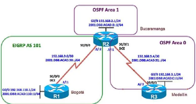
Una empresa de confecciones posee tres sucursales distribuidas en las ciudades de Bogotá, Medellín y Bucaramanga, en donde el estudiante será el administrador de la red, el cual deberá configurar e interconectar entre sí cada uno de los dispositivos que forman parte del escenario, acorde con los lineamientos establecidos para el direccionamiento IP, protocolos de enrutamiento y demás aspectos que forman parte de la topología de red.
Ilustración 1. Topología escenario 1
Configurar la topología de red, de acuerdo con las siguientes especificaciones. Parte 1: Configuración del escenario propuesto
13
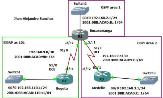
Ilustración 2.Topología implementada en GNS3
2. Ajustar el ancho de banda a 128 kbps sobre cada uno de los enlaces seriales ubicados en R1, R2, y R3 y ajustar la velocidad de reloj de las conexiones de DCE según sea apropiado.
Configuración router Bogotá (R1) R1#conf t
R1(config)#hostname Bogota Bogota(config)#int s1/0
Bogota(config-if)#ip address 192.168.9.1 255.255.255.252 Bogota(config-if)#ipv6 address 2001:DB8:ACAD:90::1/64 Bogota(config-if)# clock rate 128000
Bogota(config-if)# bandwidth 128 Bogota (config-if)#no shutdown Bogota(config)#int g0/0
14
Ilustración 3 Configuración básica router R1
Configuración router Bucaramanga (R2) R2#conf t
R2(config)#hostname Bucaramanga Bucaramanga(config-if)#int s1/0
Bucaramanga(config-if)#ip address 192.168.9.2 255.255.255.252 Bucaramanga(config-if)#ipv6 address 2001:DB8:ACAD:90::2/64 Bucaramanga (config-if)#no shutdown
Bucaramanga(config-if)#int s1/1
Bucaramanga(config-if)#ip address 192.168.9.5 255.255.255.252 Bucaramanga(config-if)#ipv6 address 2001:DB8:ACAD:91::1/64 Bucaramanga (config-if)# clock rate 128000
Bucaramanga (config-if)# bandwidth 128 Bucaramanga (config-if)#no shutdown Bucaramanga(config)#int g0/0
Bucaramanga(config-if)#ip address 192.168.2.1 255.255.255.0 Bucaramanga(config-if)#ipv6 address 2001:DB8:ACAD:B::1/64 Bucaramanga (config-if)#no shutdown
15 R3#conf t
R3(config)#hostname Medellin Medellin(config-if)#int s1/1
Medellin(config-if)#ip address 192.168.9.6 255.255.255.252 Medellin(config-if)#ipv6 address 2001:DB8:ACAD:91::2/64 Medellin(config-if)# no shutdown
Medellin(config)#int g0/0
Medellin(config-if)#ip address 192.168.3.1 255.255.255.0 Medellin(config-if)#ipv6 address 2001:DB8:ACAD:C::1/64 Medellin(config-if)# no shutdown
Ilustración 5 Configuración básica router R3
3. En R2 y R3 configurar las familias de direcciones OSPFv3 para IPv4 e IPv6. Utilice el identificador de enrutamiento 2.2.2.2 en R2 y 3.3.3.3 en R3 para ambas familias de direcciones.
Configuración router Bucaramanga (R2) Bucaramanga(config)# ipv6 unicast-routing Bucaramanga(config)# router ospfv3 1
Bucaramanga(config-router)# address-family ipv4 unicast Bucaramanga(config-router-af)# router-id 2.2.2.2
Bucaramanga(config-router-af)# exit-address-family Bucaramanga(config-router)# address-family ipv6 unicast Bucaramanga(config-router-af)# router-id 2.2.2.2
16
Ilustración 6 Configurar las familias de direcciones OSPFv3 en R2
Medellin (config)# ipv6 unicast-routing Medellin (config)# router ospfv3 1
Medellin (config-router)# address-family ipv4 unicast Medellin (config-router-af)# router-id 3.3.3.3
Medellin (config-router-af)# exit-address-family Medellin (config-router)# address-family ipv6 unicast Medellin (config-router-af)# router-id 3.3.3.3
Medellin (config-router-af)# exit-addess-family Medellin (config-router)# exit
Ilustración 7 Configurar las familias de direcciones OSPFv3 en R3
4. En R2, configurar la interfaz G0/0 en el área 1 de OSPF y la conexión serial entre R2 y R3 en OSPF área 0.
Configuración router Bucaramanga (R2) Bucaramanga(config)# int g0/0
Bucaramanga(config-if)# ip ospf network point-to-point Bucaramanga(config-if)# exit
Bucaramanga(config)# router ospf 1
Bucaramanga(config-router)# network 192.168.2.0 0.0.0.255 area 1 Bucaramanga(config-router)# network 192.168.9.2 0.0.0.3 area 2 Bucaramanga(config)# int g0/0
17 Bucaramanga(config-if)# exit
Bucaramanga(config)# int s1/1
Bucaramanga(config-if)# ospfv3 1 ipv6 area 2 Bucaramanga(config-if)# exit
Ilustración 8 Configurar OSPF en R2
5. En R3, configurar la interfaz G0/0 y la conexión serial entre R2 y R3 en OSPF área 0.
Configuración router Medellin (R3) Medellin(config)# int g0/0
Medellin(config-if)# ip ospf network point-to-point Medellin(config-if)# exit
Medellin(config)# router ospf 1
Medellin(config-router)# network 192.168.3.0 0.0.0.255 area 2 Medellin(config-router)# network 192.168.9.4 0.0.0.3 area 2 Medellin(config)# int g0/0
Medellin(config-if)# ospfv3 1 ipv6 area 2
Medellin(config-if)# ip ospf network point-to-point Medellin(config-if)# exit
Medellin(config)# int serial 1/1
Medellin(config-if)# ospfv3 1 ipv6 area 2 Medellin(config-if)# exit
Ilustración 9 Configurar OSPF en R3
18 Configuración router Bucaramanga (R2) Bucaramanga(config)# router ospfv3 1
Bucaramanga(config-router)# address-family ipv4 unicast Bucaramanga(config-router-af)# area 1 stub no-summary Bucaramanga(config-router-af)# exit-address-family Bucaramanga(config-router)# address-family ipv6 unicast Bucaramanga(config-router-af)# area 1 stub no-summary Bucaramanga(config-router-af)# exit-address-family
Ilustración 10 Configurar el área 1 como totalmente Stubby.
7. Propagar rutas por defecto de IPv4 y IPv6 en R3 al interior del dominio OSPFv3. Nota: Es importante tener en cuenta que una ruta por defecto es diferente a la definición de rutas estáticas.
Configuración router Medellin (R3) Medellin(config)# router ospfv3 1
Medellin(config-router)# address-family ipv4 unicast
Medellin(config-router-af)# default-information originate always Medellin(config-router-af)# exit-address-family
Medellin(config-router)# address-family ipv6 unicast
Medellin(config-router-af)# default-information originate always Medellin(config-router-af)# exit-address-family
Medellin(config-router)# end
19
8. Realizar la configuración del protocolo EIGRP para IPv4 como IPv6. Configurar la interfaz g0/0 de R1 y la conexión entre R1 y R2 para EIGRP con el sistema autónomo 101. Asegúrese de que el resumen automático está desactivado.
9. Configurar las interfaces pasivas para EIGRP según sea apropiado.
Configuración router Bogotá (R1) Bogota(config)# router eigrp 101
Bogota(config-router)# no auto-summary Bogota(config-router)# network 192.168.9.0 Bogota(config-router)# network 192.168.110.0 Bogota(config-router)# passive-interface g0/0 Bogota(config-router)# exit
Bogota(config)# ipv6 unicast-routing Bogota(config)# ipv6 router eigrp 101 Bogota(config-rtr)# passive-interface g0/0 Bogota(config-rtr)# eigrp router-id 1.1.1.1 Bogota(config-rtr)# no shutdown
Bogota(config-rtr)# exit
Bogota(config)# interface g0/0
Bogota(config-if)# ipv6 eigrp 101 Bogota(config-if)# exit
Bogota(config)# interface s1/0 Bogota(config-if)# ipv6 eigrp 101 Bogota(config-if)# exit
20 Configuración router Bucaramanga (R2) Bucaramanga(config)# router eigrp 101
Bucaramanga(config-router)# no auto-summary Bucaramanga(config-router)# network 192.168.9.0 Bucaramanga(config-router)#passive-interface g0/0 Bucaramanga(config-router)# exit
Bucaramanga(config)# ipv6 unicast-routing Bucaramanga(config)# ipv6 router eigrp 101
Bucaramanga(config-router)#passive-interface g0/0 Bucaramanga(config-rtr)# eigrp router-id 2.2.2.2 Bucaramanga(config-rtr)# no shutdown
Bucaramanga(config-rtr)# exit
Bucaramanga(config)# interface g0/0
Bucaramanga(config-if)# ipv6 eigrp 101 Bucaramanga(config-if)# exit
Bucaramanga(config)# interface s1/0 Bucaramanga(config-if)# ipv6 eigrp 101 Bucaramanga(config-if)# exit
Ilustración 13 Configuración del protocolo EIGRP para IPv4 / IPv6 en R2
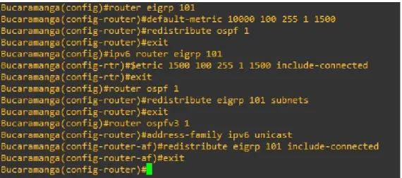
10. En R2, configurar la redistribución mutua entre OSPF y EIGRP para IPv4 e IPv6. Asignar métricas apropiadas cuando sea necesario.
Configuración router Bucaramanga (R2) Configuración router Bucaramanga (R2) Bucaramanga(config)#router eigrp 101
Bucaramanga(config-router)#default-metric 10000 100 255 1 1500 Bucaramanga(config-router)#redistribute ospf 1
21
Bucaramanga(config)#ipv6 router eigrp 101
Bucaramanga(config-rtr)#$etric 1500 100 255 1 1500 include-connected Bucaramanga(config-rtr)#exit
Bucaramanga(config)#router ospf 1
Bucaramanga(config-router)#redistribute eigrp 101 subnets Bucaramanga(config-router)#exit
Bucaramanga(config)#router ospfv3 1
Bucaramanga(config-router)#address-family ipv6 unicast
Bucaramanga(config-router-af)#redistribute eigrp 101 include-connected Bucaramanga(config-router-af)#exit
Ilustración 14 Configurar la redistribución mutua entre OSPF y EIGRP para R2
11. En R2, de hacer publicidad de la ruta 192.168.3.0/24 a R1 mediante una lista de distribución y ACL.
Configuración router Bucaramanga (R2)
Bucaramanga(config)# ip Access-list standard Medellin-to-Bogota Bucaramanga(config-std-nacl)#remark ACL to filter 192.168.3.0/24 Bucaramanga(config-std-nacl)#deny 192.168.3.0 0.0.0.255
Bucaramanga(config-std-nacl)#permit any
22
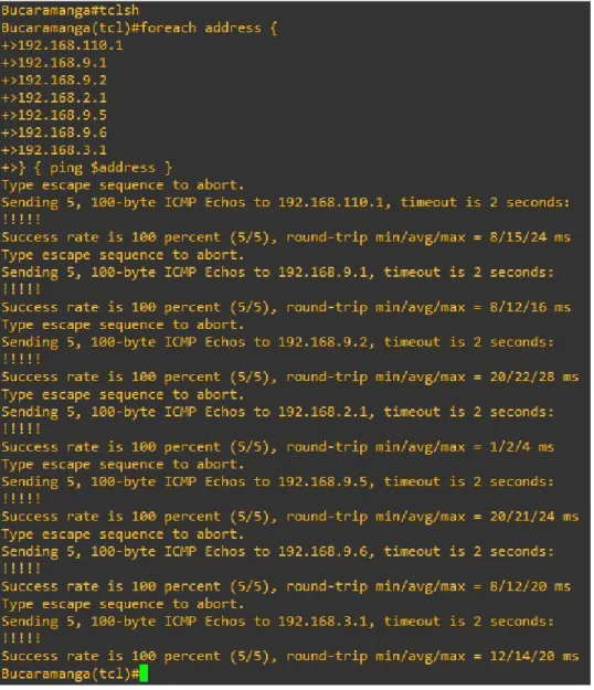
Parte 2: Verificar conectividad de red y control de la trayectoria.
1. Registrar las tablas de enrutamiento en cada uno de los routers, acorde con los parámetros de configuración establecidos en el escenario propuesto. 2. Verificar comunicación entre routers mediante el comando ping y traceroute 3. Verificar que las rutas filtradas no están presentes en las tablas de
enrutamiento de los routers correctas.
Nota: Puede ser que Una o más direcciones no serán accesibles desde todos los routers después de la configuración final debido a la utilización de listas de distribución para filtrar rutas y el uso de IPv4 e IPv6 en la misma red. Bogota# show ip route
23 Bucaramanga# show ip route
24 Medellin# show ip route
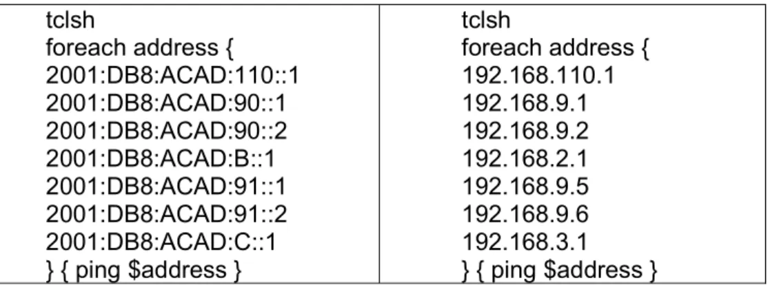
25 tclsh
foreach address { 2001:DB8:ACAD:110::1 2001:DB8:ACAD:90::1 2001:DB8:ACAD:90::2 2001:DB8:ACAD:B::1 2001:DB8:ACAD:91::1 2001:DB8:ACAD:91::2 2001:DB8:ACAD:C::1 } { ping $address }
tclsh
foreach address { 192.168.110.1 192.168.9.1 192.168.9.2 192.168.2.1 192.168.9.5 192.168.9.6 192.168.3.1 } { ping $address }
26
27
28
29
30
31 Escenario 2
Una empresa de comunicaciones presenta una estructura Core acorde a la topología de red, en donde el estudiante será el administrador de la red, el cual deberá configurar e interconectar entre sí cada uno de los dispositivos que forman parte del escenario, acorde con los lineamientos establecidos para el direccionamiento IP, etherchannels, VLANs y demás aspectos que forman parte del escenario propuesto.
Ilustración 25 Topología escenario 2
32
1. Apagar todas las interfaces en cada switch. switch#conf t
switch(config)#interface range e0/1-3, e1/0-3 switch(config-if-range)#shut
switch(config-if-range)#shutdown
Ilustración 27 Apagado de todas las interfaces
2. Asignar un nombre a cada switch acorde al escenario establecido. switch#conf t
switch(config)#hostname DLS1
Ilustración 28 Cambio de nombre de los switch
3. Configurar los puertos troncales y Port-channels tal como se muestra en el diagrama.
4. La conexión entre DLS1 y DLS2 será un EtherChannel capa-3 utilizando LACP. Para DLS1 se utilizará la dirección IP 10.12.12.1/30 y para DLS2 utilizará 10.12.12.2/30.
DLS1(config)#interface vlan 800
DLS1(config-if)#ip address 10.12.12.1 255.255.255.252 DLS1(config-if)#interface range e1/0-1
DLS1(config-if-range)#channel-protocol lacp
33
Ilustración 29 Configurar EterChanel para DLS1
DLS2(config)#interface vlan 800
DLS2(config-if)#ip address 10.12.12.2 255.255.255.252 DLS2(config-if)#interface range e1/0-1
DLS2(config-if-range)#channel-protocol lacp
DLS2(config-if-range)#channel-group 12 mode active DLS2(config-if-range)#no shutdown
Ilustración 30 Configurar EterChanel para DLS2
5. Los Port-channels en las interfaces Fa0/7 y Fa0/8 utilizarán LACP. DLS1(config)#interface range e0/0-1
DLS1(config-if-range)#channel-protocol lacp
DLS1(config-if-range)#channel-group 1 mode active DLS1(config-if-range)#no shutdown
Ilustración 31 Configuración PortChanel para e0/0-1 en DLS1
ALS1(config)#interface range e0/0-1
ALS1(config-if-range)#channel-protocol lacp
34
Ilustración 32 Configuración PortChanel para e0/0-1 en ALS1
DLS2(config)#interface range e0/0-1
DLS2(config-if-range)#channel-protocol lacp
DLS2(config-if-range)#channel-group 1 mode active DLS2(config-if-range)#no shutdown
Ilustración 33 Configuración PortChanel para e0/0-1 en DLS2
ALS2(config)#interface range e0/0-1
ALS2(config-if-range)#channel-protocol lacp
ALS2(config-if-range)#channel-group 1 mode active ALS2(config-if-range)#no shutdown
35
6. Los Port-channels en las interfaces F0/9 y fa0/10 utilizará PAgP. DLS1(config)#interface range e0/2-3
DLS1(config-if-range)#channel-protocol pagp
DLS1(config-if-range)#channel-group 4 mode active DLS1(config-if-range)#no shutdown
Ilustración 35 Configuración PortChanel para e0/2-3 en DLS1
ALS1(config)#interface range e0/2-3
ALS1(config-if-range)#channel-protocol pagp
ALS1(config-if-range)#channel-group 3 mode active ALS1(config-if-range)#no shutdown
Ilustración 36 Configuración PortChanel para e0/2-3 en ALS1
DLS2(config)#interface range e0/2-3
DLS2(config-if-range)#channel-protocol pagp
36
Ilustración 37 Configuración PortChanel para e0/2-3 en DLS2
ALS2(config)#interface range e0/2-3
ALS2(config-if-range)#channel-protocol pagp
ALS2(config-if-range)#channel-group 4 mode active ALS2(config-if-range)#no shutdown
Ilustración 38 Configuración PortChanel para e0/2-3 en ALS2
7. Todos los puertos troncales serán asignados a la VLAN 800 como la VLAN nativa.
DLS1(config)#int ran e0/0-3, e1/0-1
DLS1(config-if-range)#switchport trunk encap dot1q DLS1(config-if-range)#switchport trunk native vlan 800 DLS1(config-if-range)#switchport mode trunk
DLS1(config-if-range)#switchport nonegotiate DLS1(config-if-range)#no shut
DLS1(config-if-range)#exit
37 DLS2(config)#int ran e0/0-3, e1/0-1
DLS2(config-if-range)#switchport trunk encap dot1q DLS2(config-if-range)#switchport trunk native vlan 800 DLS2(config-if-range)#switchport mode trunk
DLS2(config-if-range)#switchport nonegotiate DLS2(config-if-range)#no shut
DLS2(config-if-range)#exit
Ilustración 40 Puertos troncales asignados a la VLAN 800 en DLS2
ALS1(config)#int ran e0/0-3
ALS1(config-if-range)#switchport trunk encap dot1q ALS1(config-if-range)#switchport trunk native vlan 800 ALS1(config-if-range)#switchport mode trunk
ALS1(config-if-range)#switchport nonegotiate ALS1(config-if-range)#no shut
ALS1(config-if-range)#exit
Ilustración 41 Puertos troncales asignados a la VLAN 800 en DLS2
ALS2(config)#int ran e0/0-3
ALS2(config-if-range)#switchport trunk encap dot1q ALS2(config-if-range)#switchport trunk native vlan 800 ALS2(config-if-range)#switchport mode trunk
ALS2(config-if-range)#switchport nonegotiate ALS2(config-if-range)#no shut
38
Ilustración 42 Puertos troncales asignados a la VLAN 800 en ALS2
8. Configurar DLS1, ALS1, y ALS2 para utilizar VTP versión 3 a. Utilizar el nombre de dominio UNAD con la contraseña cisco123 b. Configurar DLS1 como servidor principal para las VLAN.
DLS1(config)#vtp domain UNAD DLS1(config)#vtp version 3
DLS1(config)#vtp password cisco123 DLS1(config)#vtp mode server
Ilustración 43 Configurar DLS1 para VTP v3 como servidor + clave
c. Configurar ALS1 y ALS2 como clientes VTP. ALS1(config)#vtp domain UNAD
ALS1(config)# spanning-tree mode mst ALS1(config)# vtp version 3
ALS1(config)# vtp mode client mst
Ilustración 44 Configurar ALS1 para VTP v3 y cliente
ALS1(config)#vtp domain UNAD
ALS2(config)# spanning-tree mode mst ALS2(config)# vtp version 3
39
Ilustración 45 Configurar ALS2 para VTP v3 y cliente
9. Configurar en el servidor principal las siguientes VLAN: Tabla 1. Configuración de Vlan
DLS1(config)# vtp mode transparent DLS1(config)#vlan 800 DLS1(config-vlan)#name NATIVA DLS1(config)#exit DLS1(config)#vlan 12 DLS1(config-vlan)#name EJECUTIVOS DLS1(config)#exit DLS1(config)#vlan 234 DLS1(config-vlan)#name HUESPEDES DLS1(config)#exit DLS1(config)#vlan 1111 DLS1(config-vlan)#name VIDEONET DLS1(config)#exit
DLS1(config)#vlan 434
DLS1(config-vlan)#name ESTACIONAMIENTO DLS1(config)#exit DLS1(config)#vlan 123 DLS1(config-vlan)#name MANTENIMIENTO DLS1(config)#exit DLS1(config)#vlan 1010 DLS1(config-vlan)#name VOZ DLS1(config)#exit DLS1(config)#vlan 3456 DLS1(config-vlan)#name ADMINISTRACION DLS1(config)#exit
40
Ilustración 46Configuración de Vlan en DLS1
10. En DLS1, suspender la VLAN 434. DLS1(config)# vtp mode transparent DLS1(config)#vlan 434
DLS1(config-vlan)# state suspend DLS1(config-vlan)#exit
DLS1(config)#no vtp mode transparent
41
11. Configurar DLS2 en modo VTP transparente VTP utilizando VTP versión 2, y configurar en DLS2 las mismas VLAN que en DLS1.
DLS2(config)#vttp version 2
DLS1(config)# vtp mode transparent DLS2(config)#vlan 800
DLS2(config-vlan)#name NATIVA DLS2(config)#vlan 12
DLS2(config-vlan)#name EJECUTIVOS DLS2(config)#vlan 234
DLS2(config-vlan)#name HUESPEDES DLS2(config)#vlan 1111
DLS2(config-vlan)#name VIDEONET DLS2(config)#vlan 434
DLS2(config-vlan)#name ESTACIONAMIENTO DLS2(config)#vlan 123
DLS2(config-vlan)#name MANTENIMIENTO DLS2(config)#vlan 1010
DLS2(config-vlan)#name VOZ DLS2(config)#vlan 3456
DLS2(config-vlan)#name ADMINISTRACION
42 12. Suspender VLAN 434 en DLS2.
DLS2(config)# vtp mode transparent DLS2(config)#vlan 434
DLS2(config-vlan)# state suspend DLS2(config-vlan)#exit
DLS2(config)#no vtp mode transparent
Ilustración 49 En DLS2 suspender VLAN 434
13. En DLS2, crear VLAN 567 con el nombre de CONTABILIDAD. La VLAN de CONTABILIDAD no podrá estar disponible en cualquier otro Switch de la red. DLS2(config)# vtp mode transparent
DLS2(config)#vlan 567
DLS2(config-vlan)# private-vlan isolated DLS2(config-vlan)# name CONTABILIDAD DLS2(config-vlan)#exit
DLS2(config)#no vtp mode transparent
Ilustración 50 10. En DLS2 se crea y configura la VLAN 567
14. Configurar DLS1 como Spanning tree root para las VLAN 1, 12, 434, 800, 1010, 1111 y 3456 y como raíz secundaria para las VLAN 123 y 234.
DLS1(config)#spanning-tree vlan 1,12,434,800,1010,1111,3456 root primary DLS1(config)#spanning-tree vlan 123,234 root secondary
43
15. Configurar DLS2 como Spanning tree root para las VLAN 123 y 234 y como una raíz secundaria para las VLAN 12, 434, 800, 1010, 1111 y 3456.
DLS2(config)#spanning-tree vlan 123,234 root primary
DLS2(config)#spanning-tree vlan 1,12,434,800,1010,1111,3456 root secondary
Ilustración 52 Configuración en DLS2 Spanning tree root secondary
16. Configurar todos los puertos como troncales de tal forma que solamente las VLAN que se han creado se les permitirá circular a través de estos puertos.
DLS1(config)# int ran e0/0-3, e1/0-1
DLS1(config-if-range)# switchport trunk encap dot1q DLS1(config-if-range)# switchport trunk native vlan 800 DLS1(config-if-range)# switchport mode trunk
DLS1(config-if-range)#exit
Ilustración 53 En DLS1 se asignan puertos troncales solo a las Vlan creadas
DLS2(config)#int ran e0/0-3, e1/0-1
DLS2(config-if-range)#switchport trunk encap dot1q DLS2(config-if-range)#switchport trunk native vlan 800 DLS2(config-if-range)#switchport mode trunk
DLS2(config-if-range)#exit int ran e0/0-3, e1/0-1
44 ALS1(config)#int ran e0/0-3
ALS1(config-if-range)# switchport trunk encap dot1q ALS1(config-if-range)# switchport trunk native vlan 800 ALS1(config-if-range)# switchport mode trunk
ALS1(config-if-range)#exit
Ilustración 55 En ALS1 se asignan puertos troncales solo a las Vlan creadas
ALS2(config)# int ran e0/0-3
ALS2(config-if-range)# switchport trunk encap dot1q ALS2(config-if-range)# switchport trunk native vlan 800 ALS2(config-if-range)# switchport mode trunk
ALS2(config-if-range)#exit
Ilustración 56 En ALS2 se asignan puertos troncales solo a las Vlan creadas
17. Configurar las siguientes interfaces como puertos de acceso, asignados a las VLAN de la siguiente manera:
Tabla 2. Configuración de interfaces para cada Vlan
Interfaz DLS1 DLS2 ALS1 ALS2
e1/2 3456 12, 1010 123,1010 234
e2/1 1111 1111 1111 1111
e2/2-3 567
DLS1(config)# interface e1/2
DLS1(config-if)#switchport access vlan 3456 DLS1(config-if)#no shutdown
DLS1(config-if)# exit
DLS1(config)# interface e 2/1
45
Ilustración 57 Configuración de interfaces y Vlan en DLS1
DLS2(config)# interface e1/2
DLS2(config-if)#switchport access vlan 12 DLS2(config-if)#switchport access vlan 1010 DLS2(config-if)#no shutdown
DLS2(config-if)# exit
DLS2(config)# interface e 2/1
DLS2(config-if)#switchport access vlan 1111 DLS2(config-if)#no shutdown
Ilustración 58 Configuración de interfaces y Vlan en DLS2
ALS1(config)# interface e1/2
ALS1(config-if)#switchport access vlan 123 ALS1(config-if)#switchport access vlan 1010 ALS1(config-if)#no shutdown
ALS1(config-if)# exit
ALS1(config)# interface e 2/1
46
Ilustración 59 Configuración de interfaces y Vlan en ALS1
ALS2(config)# interface e1/2
ALS2(config-if)#switchport access vlan 234 ALS2(config-if)#no shutdown
ALS2(config-if)# exit
ALS2(config)# interface e 2/1
ALS2(config-if)#switchport access vlan 1111 ALS2(config-if)#no shutdown
47
Parte 2: Conectividad de red de prueba y las opciones configuradas.
1. Verificar la existencia de las VLAN correctas en todos los switches y la asignación de puertos troncales y de acceso
DLS1# show vlan
DLS1# show ip interface brief DLS1# show vtp status
Ilustración 61 Verificación de DLS1 con show vlan
48
Ilustración 63 Verificación de DLS1 con show vtp status
Ilustración 64 Verificación de DLS2 con show vlan
49
Ilustración 66 Verificación de DLS2 con show vtp status
50
Ilustración 68 Verificación deALS1 con show interface brief
51
lustración 70 Verificación de ALS2 con show vlan
Ilustración 71 Verificación de ALS2 con show interface brief
52
b. Verificar que el EtherChannel entre DLS1 y ALS1 está configurado correctamente c. Verificar la configuración de Spanning tree entre DLS1 o DLS2 para cada VLAN.
Ilustración 73 Verificación DLS1 con show spanning-tree Parte 1
53
Ilustración 75 Verificación DLS1 con show spanning-tree Parte 3
54
Ilustración 77 Verificación DLS1 con show spanning-tree Parte 5
55
Ilustración 79 Verificación DLS2 con show spanning-tree Parte 2
56
Ilustración 81 Verificación DLS2 con show spanning-tree Parte 4
57
CONCLUSIONES
Gracias a los conocimientos adquiridos a lo largo del diplomado de profundización de redes de comunicación CCNP CISCO, se logra realizarla implementación de las los escenarios planteados en el software GNS3 en el cual se desarrolla la codificación adecuada para las configuración y conectividad de los router y switch según las topologías de cada ejercicio.
En el desarrollo del escenario 1, donde aplicamos los conocimientos de conectividad de router, se logra la configuración adecuada de la red de comunicación implementado los protocolos OSPF para el área 0 correspondiente a la ciudad de Medellín, el área 1 correspondiente a la ciudad de Bucaramanga y el protocolo EIGRP AS 101 correspondiente a la ciudad de Bogotá en la cuales se aplicó direccionamiento IPv4 e IPv6 logrando la redistribución mutua entre OSPF y EIGRP y la comunicación efectiva entre las áreas.
En el desarrollo del escenario 2, se aplicaron los conocimientos de conectividad de switch con lo que es posible realizar las configuraciones adecuadas para la red; se logró habilitar la conexión entre las troncales DLS1 y DLS2 basados en los EtherChanel Capa 3 mediante el protocolos LACP; Se logró la configuración adecuada de las redes de área local virtual (Vlan) lo que nos permite sectorizar la comunicación en la red donde mediante el protocolo VTP v3 se logra la distribución de las Vlan a toda la red siendo DLS1 el servidor primario y ALS1 y ALS2 los clientes en la que todos los puertos troncales están asignados a la vlan 800 nativa. .
58
BIBLIOGRAFIA
Froom, R., Frahim, E. (2015). CISCO Press (Ed). First Hop Redundancy Protocols. Implementing Cisco IP Switched Networks (SWITCH) Foundation Learning Guide CCNP SWITCH 300-115. Recuperado de https://1drv.ms/b/s!AmIJYei-NT1IlnWR0hoMxgBNv1CJ
Froom, R., Frahim, E. (2015). CISCO Press (Ed). Network Management. Implementing Cisco IP Switched Networks (SWITCH) Foundation Learning Guide CCNP SWITCH 300-115. Recuperado de https://1drv.ms/b/s!AmIJYei-NT1IlnWR0hoMxgBNv1CJ
Froom, R., Frahim, E. (2015). CISCO Press (Ed). v. Implementing Cisco IP Switched Networks (SWITCH) Foundation Learning Guide CCNP SWITCH 300-115.
Recuperado de
https://1drv.ms/b/s!AmIJYei-NT1IlnWR0hoMxgBNv1CJ
Froom, R., Frahim, E. (2015). CISCO Press (Ed). High Availability. Implementing Cisco IP Switched Networks (SWITCH) Foundation Learning Guide CCNP SWITCH
300-115. Recuperado de
https://1drv.ms/b/s!AmIJYei-NT1IlnWR0hoMxgBNv1CJ
Froom, R., Frahim, E. (2015). CISCO Press (Ed). Campus Network Security. Implementing Cisco IP Switched Networks (SWITCH) Foundation Learning Guide CCNP SWITCH 300-115. Recuperado de https://1drv.ms/b/s!AmIJYei-NT1IlnWR0hoMxgBNv1CJ
UNAD (2015). Switch CISCO Security Management [OVA]. Recuperado de https://1drv.ms/u/s!AmIJYei-NT1IlyVeVJCCezJ2QE5c
Macfarlane, J. (2014). Network Routing Basics : Understanding IP Routing in Cisco
Systems. Recuperado
de http://bibliotecavirtual.unad.edu.co:2048/login?url=http://search.ebscohost.com/l ogin.aspx?direct=true&db=e000xww&AN=158227&lang=es&site=ehost-live
Hucaby, D. (2015). CISCO Press (Ed). CCNP Routing and Switching SWITCH
300-115 Official Cert Guide. Recuperado de
https://1drv.ms/b/s!AgIGg5JUgUBthF16RWCSsCZnfDo2
59
Froom, R., Frahim, E. (2015). CISCO Press (Ed). Switch Fundamentals Review. Implementing Cisco IP Switched Networks (SWITCH) Foundation Learning Guide CCNP SWITCH 300-115. Recuperado de https://1drv.ms/b/s!AmIJYei-NT1IlnWR0hoMxgBNv1CJ
Froom, R., Frahim, E. (2015). CISCO Press (Ed). Network Design Fundamentals. Implementing Cisco IP Switched Networks (SWITCH) Foundation Learning Guide CCNP SWITCH 300-115. Recuperado de https://1drv.ms/b/s!AmIJYei-NT1IlnWR0hoMxgBNv1CJ
Froom, R., Frahim, E. (2015). CISCO Press (Ed). Campus Network Architecture. Implementing Cisco IP Switched Networks (SWITCH) Foundation Learning Guide CCNP SWITCH 300-115. Recuperado de https://1drv.ms/b/s!AmIJYei-NT1IlnWR0hoMxgBNv1CJ
Temática: Spanning Tree Implementation
Froom, R., Frahim, E. (2015). CISCO Press (Ed). Spanning Tree Implementation. Implementing Cisco IP Switched Networks (SWITCH) Foundation Learning Guide CCNP SWITCH 300-115. Recuperado de https://1drv.ms/b/s!AmIJYei-NT1IlnWR0hoMxgBNv1CJ
Temática: InterVLAN Routing