DIPLOMADO DE PROFUNDIZACION CISCO PRUEBA DE HABILIDADES PRÁCTICAS CCNP
JOSÉ EFRAIN CORDOBA PAREDES
UNIVERSIDAD NACIONAL ABIERTA Y A DISTANCIA - UNAD ESCUELA DE CIENCIAS BÁSICAS, TECNOLOGÍA E INGENIERÍA - ECBTI
INGENIERÍA DE TELECOMUNICACIONES
NEIVA
DIPLOMADO DE PROFUNDIZACION CISCO PRUEBA DE HABILIDADES PRÁCTICAS CCNP
JOSÉ EFRAIN CORDOBA PAREDES
Diplomado de opción de grado presentado para optar el título de INGENIERO DE TELECOMUNICACIONES
DIRECTOR:
MSc. GERARDO GRANADOS ACUÑA
UNIVERSIDAD NACIONAL ABIERTA Y A DISTANCIA - UNAD ESCUELA DE CIENCIAS BÁSICAS, TECNOLOGÍA E INGENIERÍA - ECBTI
INGENIERÍA DE TELECOMUNICACIONES
NEIVA
NOTA DE ACEPTACIÓN
Firma del Presidente del Jurado
Firma del Jurado
Firma del Jurado
AGRADECIMIENTOS
"Quiero agradecer de manera infinita a toda mi familia por el apoyo brindado
durante este tiempo de preparación profesional, a mi esposa e hijos quien han sido
un pilar fundamental para lograr este título como Ingeniero en Telecomunicaciones
y finalmente a mis maestros quienes siempre me guiaron para lograr el éxito
CONTENIDO
AGRADECIMIENTOS ... 4
CONTENIDO ... 5
LISTA DE TABLAS ... 6
LISTA DE FIGURAS ... 7
RESUMEN ... 10
ABSTRACT ... 10
INTRODUCCIÓN ... 11
1. ESCENARIO 1 ... 12
2. ESCENARIO 2 ... 27
Parte 1: Configurar la red de acuerdo con las especificaciones. ... 27
Parte 2: conectividad de red de prueba y las opciones configuradas. ... 47
CONCLUSIONES ... 59
LISTA DE TABLAS
Tabla 1. VLAN asignada para creación ... 47
LISTA DE FIGURAS
Figura 1. Escenario 1 12
Figura 2. Simulación del escenario 1 12
Figura 3. Configuración Ancho de banda R1 15
Figura 4. Configuración Protocolo de Enrutamiento OSPF 16
Figura 5. Configuración OSPF en interfaz 17
Figura 6. Configuración OSPF en enlace serial 18
Figura 7. Configuración área Stubby en R2 18
Figura 8. Configuración rutas por defecto en R3 19
Figura 9. Configuración protocolo EIGRP en R1 19
Figura 10. Configuración protocolo EIGRP en R2 20
Figura 11. Configuración interfaces pasivas en R1 21
Figura 12. Configuración interfaces pasivas en R2 21
Figura 13. Asignación de métricas OSPF para R2 22
Figura 14. Configuración de ACL en R2 22
Figura 15. Visualización tabla de enrutamiento R1 23
Figura 16. Comando SHOW IP EIGRP NEGHBOR R1 23
Figura 17. Visualización tabla de enrutamiento R2 23
Figura 18. Comando SHOW IP OSPF NEGHBOR R2 24
Figura 19. Visualización tabla de enrutamiento R3 24
Figura 21. Comunicación entre R1 y R2. Comando ping 24
Figura 22. Comunicación entre R1 y R2. Comando
traceroute
25
Figura 23. Comunicación entre R2 y R3. Comando ping 25
Figura 24. Comunicación entre R2 y R3. Comando
traceroute
25
Figura 25. Comunicación entre R1 y R3. Comando ping 25
Figura 26. Comunicación entre R1 y R3. Comando
traceroute
25
Figura 27. Escenario 2 27
Figura 28. Simulación del Escenario 2 27
Figura 29. Verificación creación de VLAN en DLS1 38
Figura 30. Modos de operación VTP en DLS1 38
Figura 31. Modos de operación VTP en DLS1 39
Figura 32. Modos de operación VTP en ALS2 39
Figura 33. Modos de operación VTP en ALS2 39
Figura 34 . Modos de operación VTP en ALS1 40
Figura 35 . Modos de operación VTP en ALS1 40
Figura 36. Modos de operación VTP en ALS1 41
Figura 37. Resultado comando show vlan brief para DLS1 48
Figura 38. Resultado show running-config para DLS1 48
Figura 40. Resultado show running-config para DLS2 50
Figura 41. Resultado comando show vlan brief para ALS1 51
Figura 42. Resultado show running-config para ALS1 52
Figura 43. Resultado comando show vlan brief para ALS2 53
Figura 44. Resultado show running-config para ALS2 54
Figura 45. Configuración EtherChannel DLS1 55
Figura 46. Configuración EtherChannel DLS2 56
Figura 47. Configuración EtherChannel ALS1 57
Figura 48. Configuración Spanning-tree para DLS1 57
RESUMEN
En la certificación de CNNP se trabajaron los temas de routing, switching y troubleshooting de forma específica, pues se debe profundizar para obtener una mayor calidad, seguridad y rendimiento en las prácticas desarrolladas. Se desarrollaron dos módulos durante el diplomado de profundización: CCNP ROUTE y CCNP SWITCH.
Con este diplomado se ha logrado adquirir la capacidad de planificar, implementar, verificar y solucionar problemas de redes empresariales locales y de área amplia y trabajar en colaboración con especialistas en soluciones avanzadas de seguridad, voz, redes inalámbricas y video.
En este trabajo se identificarán situaciones asociadas con aspectos de conmutación y enrutamiento, mediante el uso eficiente de estrategias basadas en comandos IOS y estadísticas de tráfico en las interfaces, con el fin de resolver conflictos de configuración y conectividad en contextos de redes LAN y WAN.
Palabras Clave: CISCO, CCNP, OSPF.
ABSTRACT
In the CNNP certification we work on the issues of routing, change and problem solving in a specific way, because it must be deepened to obtain a higher quality, security and performance in the practices developed. Two modules were developed during the deep diploma: CCNP ROUTE and CCNP SWITCH.
With this diploma it has been possible to acquire the ability to plan, implement, verify and solve problems of local and wide area networks and work in collaboration with specialists in advanced security solutions, voice, wireless networks and video.
This paper will identify situations associated with aspects of switching and routing, through the efficient use of strategies based on IOS commands and traffic statistics on the interfaces, in order to resolve configuration and connectivity conflicts in LAN and WAN network contexts.
INTRODUCCIÓN
De acuerdo con la evolución de las tecnologías de la información y de la
comunicación es necesaria la implementación de nuevas técnicas de seguridad,
de soluciones de mayor complejidad en las situaciones que se presenten al interior
de una red cableada o inalámbrica, además de la migración de redes al protocolo
IPv6 del cual dependen servicios como la conexión de mayor cantidad de
dispositivos, de conexiones móviles desde teléfonos o tablets, y un abono a las
redes de nueva generación. Para esta transición es necesario tener en cuenta un
proceso de formación y capacitación, un análisis de la infraestructura de TI,
aplicaciones, servicios, topología, diseño del direccionamiento de la red, análisis
de interoperabilidad entre protocolos IPv4 e Ipv6, entre otros aspectos que tendrán
que considerarse para ello.
La certificación en CCNP, aborda sin fin de conceptos sobre routing y switching,
de igual forma sobre la resolución de problemas de conectividad, se considera
como una continuación del CCNA pero en un grado de complejidad más avanzado,
un nivel de calidad mucho más alto pues se trata de un nivel profesional. Con
CCNP es posible el montaje de múltiples escenarios que permiten entender las
redes, sus jerarquías, uso de switches, uso de switch multicapa, routers y otros
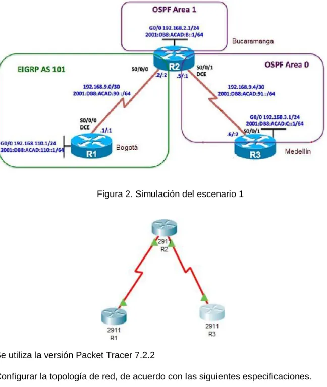
1. ESCENARIO 1
Figura 1. Escenario 1
Figura 2. Simulación del escenario 1
Se utiliza la versión Packet Tracer 7.2.2
Parte 1: Configuración del escenario propuesto
1.1. Configurar las interfaces con las direcciones IPv4 e IPv6 que se muestran en la topología de red.
Para la configuración de la interfaces en necesario ingresa al modo privilegiado con el comando enable
Posteriormente es importarte asignarle un nombre a cada uno de los router con el comando
Hostname R1
Hostname R2
Hostname R3
Configure terminal para empezar con la configuración de las interfaces
Para la configuración Ipv4 de los 3 router se ingresa a la configuración de la interfaz y es necesario habilitar el direccionamiento Ipv6, para esto se requiere del comando IPV6 unicast-routing para proceder a configurar las interfaces como se muestra a continuación:
Configuración R1:
Interface g 0/0
ip address 192.168.110.1 255.255.255.0
ipv6 address 2001:DB8:ACAD:110::1/64
ipv6 address FE80::1 Link-local
n sh
Interface s 0/0/0
ipv6 address 2001:DB8:ACAD:90::1/64
ip address 192.168.9.1 255.255.255.252
n sh
Configuración R2:
Interface g 0/0
ip address 192.168.2.1 255.255.255.0
ipv6 address 2001:DB8:ACAD:B::1/64
ipv6 address FE80::1 LInk-local
n sh
Interface s 0/0/0
ipv6 address 2001:DB8:ACAD:90::2/64 ipv6 address FE80::1 link-local
ip address 192.168.9.2 255.255.255.252 n sh
Interface s 0/0/1
ipv6 address 2001:DB8:ACAD:91::1/64 ipv6 address FE80::1 link-local
ip address 192.168.9.5 255.255.255.252 n sh
Configuración R3: Interface g 0/0
ip address 192.168.3.1 255.255.255.0 ipv6 address 2001:DB8:ACAD:C::1/64 ipv6 address FE80::1 LInk-local
no sh
Interface s 0/0/1
ipv6 address FE80::1 link-local
ip address 192.168.9.6 255.255.255.252 n sh
1.2 Ajustar el ancho de banda a 128 kbps sobre cada uno de los enlaces seriales ubicados en R1, R2, R3 y ajustar la velocidad de reloj de las conexiones de DCE según sea apropiado.
El cambio de ancho de banda se realiza mediante el comando bandwith en las interfaces en que se desee cambiar. Para ajustar la velocidad del reloj se utiliza el comando clock rate.
Configuración R1:
Interface s 0/0/0 bandwidth 128 clock rate 128000
Figura 3. Configuración Ancho de banda R1
Configuración R2:
Interface s 0/0/0 bandwidth 128 clock rate 128000
Interface s 0/0/1 bandwidth 128 clock rate 128000
1.3 En R2 y R3 configurar las familias de direcciones OSPFv3 para IPv4 e IPv6. Utilice el identificador de enrutamiento 2.2.2.2 en R2 y 3.3.3.3 en R3 para ambas familias de direcciones..
Se realiza la siguiente configuración en los router, habilitando el enrutamiento OSPF, así mismo asignando el router-id para cada uno de ellos.
Configuración R2: router ospf 1
router-id 2.2.2.2 exit
ipv6 router ospf 1 router-id 2.2.2.2
Configuración R3: router ospf 1
router-id 3.3.3.3 exit
ipv6 router ospf 1 router-id 3.3.3.3
Figura 4. Configuración Protocolo de Enrutamiento OSPF
1.4 En R2, configurar la interfaz F0/0 en el área 1 de OSPF y la conexión serial entre R2 y R3 en OSPF área 0.
Inteface g0/0 Ip ospf 1 area 1 Ipv6 ospf 1 area 1 config t
int s0/0/1
ip ospf 1 area 0 ipv6 ospf 1 a
Figura 5. Configuración OSPF en interfaz
Así mismo, para R3:
int s0/0/1
ip ospf 1 area 0 ipv6 ospf 1 area 0 end
1.5 En R3, configurar la interfaz F0/0 y la conexión serial entre R2 y R3 en OSPF área 0.
Se utiliza el siguiente código:
Interface g0/0
Ip ospf 1 area 0
Ipv6 ospf 1 area 0
Ip ospf 1 area 0
Ipv6 ospf 1 area 0
Figura 6. Configuración OSPF en enlace serial
1.6 Configurar el área 1 como un área totalmente Stubby.
Para configurar el área como stubby se utiliza el comando área 1 stub dentro del protocolo de enrutamiento, tanto para ipv4 como para ipv6
ipv6 router ospf 1
router-id 2.2.2.2
area 1 stub
Figura 7. Configuración área Stubby en R2
1.7 Propagar rutas por defecto de IPv4 y IPv6 en R3 al interior del dominio OSPFv3. Nota: Es importante tener en cuenta que una ruta por defecto es diferente a la definición de rutas estáticas.
Configuración en R3
Ruta estática por defecto:
Redistribución en ospf:
router ospf 1
default-information originate
ipv6 router ospf 1
default-information originate
Figura 8. Configuración rutas por defecto en R3
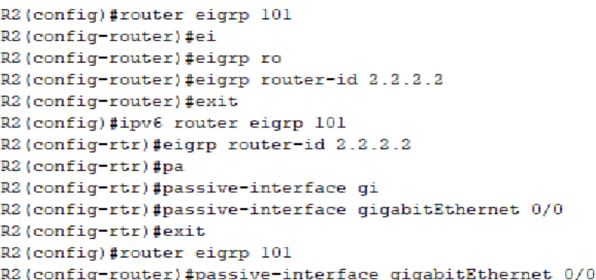
1.8 Realizar la configuración del protocolo EIGRP para IPv4 como IPv6. Configurar la interfaz F0/0 de R1 y la conexión entre R1 y R2 para EIGRP con el sistema autónomo 101. Asegúrese de que el resumen automático está desactivado.
A continuación se aprecia cómo se configura el protocolo EIGRP tanto en el R1 como en R2:
Figura 10. Configuración protocolo EIGRP en R2 y R1
1.9 Configurar las interfaces pasivas para EIGRP según sea apropiado.
Para este procedimiento se utiliza el comando passive-interface en el modo de configuración del router, con el fin de evitar la transmisión de mensajes de routing a través de una interfaz del router, pero sin dejar de permitir que se anuncie esa red a otros routers (Cisco,s.f.).
Se realiza de la siguiente manera:
Router ospf 1
Passive-interface gi0/0
Figura 11. Configuración interfaces pasivas en R1
Figura 12. Configuración interfaces pasivas en R2
1.10 En R2, configurar la redistribución mutua entre OSPF y EIGRP para IPv4 e IPv6. Asignar métricas apropiadas cuando sea necesario.
Se ingresa al modo de configuración del router, y seguido a ello al modo de configuración de protocolo eigrp.
Enable
Configure terminal
Router eigrp 101
Figura 13. Asignación de métricas OSPF para R2
1.11 En R2, de hacer publicidad de la ruta 192.168.3.0/24 a R1 mediante una lista de distribución y ACL.
La lista de acceso ACL se crea de la siguiente manera:
Figura 14. Configuración de ACL en R2
Parte 2: Verificar conectividad de red y control de la trayectoria.
Figura 15. Visualización tabla de enrutamiento R1
Figura 16. Comando SHOW IP EIGRP NEGHBOR R1
Figura 18. Comando SHOW IP OSPF NEGHBOR R2
Figura 19. Visualización tabla de enrutamiento R3
Figura 20. Comando SHOW IP OSPF NEGHBOR R3
1.13 Verificar comunicación entre routers mediante el comando ping y traceroute
Figura 22. Comunicación entre R1 y R2. Comando traceroute
Figura 23. Comunicación entre R2 y R3. Comando ping
Figura 24. Comunicación entre R2 y R3. Comando traceroute
Figura 25. Comunicación entre R1 y R3. Comando ping
1.14 Verificar que las rutas filtradas no están presentes en las tablas de enrutamiento de los routers correctas.
2. ESCENARIO 2
Figura 27. Escenario 2
Figura 28. Simulación del Escenario 2
Parte 1: Configurar la red de acuerdo con las especificaciones.
2.2 Apagar todas las interfaces en cada switch.
DLS1
Switch>enable
Switch#config t
Enter configuration commands, one per line. End with CNTL/Z.
Switch(config)#inter range g1/0/1-g1/0/24
Switch(config-if-range)#shutdown
DLS2
Switch>enable
Switch#config t
Enter configuration commands, one per line. End with CNTL/Z.
Switch(config)#inter range g1/0/1-g1/0/24
Switch(config-if-range)#shut
ALS1 y ALS2
Switch>ena
Switch#config t
Enter configuration commands, one per line. End with CNTL/Z.
Switch(config)#int range fa0/1-24
Switch(config-if-range)#shut
2.3 Asignar un nombre a cada switch acorde al escenario establecido.
Switch#config terminal
Enter configuration commands, one per line. End with CNTL/Z.
Switch(config)#hostname DLS1
DLS1(config)#
Switch#config t
Enter configuration commands, one per line. End with CNTL/Z.
Switch(config)#hostname ALS2
ALS2(config)#
2.4 Configurar los puertos troncales y Port-channels tal como se muestra en el diagrama.
1) La conexión entre DLS1 y DLS2 será un EtherChannel capa-3 utilizando LACP. Para DLS1 se utilizará la dirección IP 10.12.12.1/30 y para DLS2 utilizará 10.12.12.2/30.
Se realiza la configuración para el EtherChannel 12 en DLS1:
Switch#config terminal
Enter configuration commands, one per line. End with CNTL/Z. Switch(config)#hostname DLS1
DLS1(config)#inter range g1/0/11-g1/0/12 DLS1(config-if-range)#cha
DLS1(config-if-range)#channel-protocol lacp DLS1(config-if-range)#chann
DLS1(config-if-range)#channel-group 12 mode active DLS1(config-if-range)#
Creating a port-channel interface Port-channel 12 DLS1(config-if-range)#
De igual forma se realiza la configuración del EtherChannel 12 en DLS2:
Enter configuration commands, one per line. End with CNTL/Z. Switch(config)#hostname DLS2
DLS2(config)#inter range g1/0/11-g1/0/12 DLS2(config-if-range)#channel-protocol lacp
DLS2(config-if-range)#channel-group 12 mode active DLS2(config-if-range)#
Creating a port-channel interface Port-channel 12
2) Los Port-channels en las interfaces Fa0/7 y Fa0/8 utilizarán LACP.
Se realiza la configuración para DSL1 y DLS2 de la siguiente manera con LACP - Link Aggregation Control Protocol
DLS1(config)#int range gi1/0/7-gi1/0/8 DLS1(config-if-range)#channel-protocol lacp
DLS1(config-if-range)#channel-group 1 mode active DLS1(config-if-range)#
Creating a port-channel interface Port-channel 1 DLS1(config-if-range)#
DLS2>ena DLS2#config t
Enter configuration commands, one per line. End with CNTL/Z. DLS2(config)#int range g1/0/7-gi1/0/8
DLS2(config-if-range)#channel-protocol lacp
DLS2(config-if-range)#channel-group 2 mode active DLS2(config-if-range)#
Creating a port-channel interface Port-channel 2 DLS2(config-if-range)#
Asì mismo para ALS1 y ALS2 de la siguiente manera con LACP - Link Aggregation Control Protocol
ALS1>ena ALS1#config t
ALS1(config)#int range fa0/7-8
ALS1(config-if-range)#channel-protocol lacp
ALS1(config-if-range)#channel-group 1 mode active ALS1(config-if-range)#
Creating a port-channel interface Port-channel 1 ALS1(config-if-range)#
ALS2>ena ALS2#config t
Enter configuration commands, one per line. End with CNTL/Z. ALS2(config)#int range fa0/7-8
ALS2(config-if-range)#channel-protocol lacp
ALS2(config-if-range)#channel-group 2 mode active ALS2(config-if-range)#
Creating a port-channel interface Port-channel 2
ALS2(config-if-range)#
%LINK-5-CHANGED: Interface FastEthernet0/7, changed state to up
%LINEPROTO-5-UPDOWN: Line protocol on Interface FastEthernet0/7, changed state to up
%LINK-5-CHANGED: Interface FastEthernet0/8, changed state to up
%LINEPROTO-5-UPDOWN: Line protocol on Interface FastEthernet0/8, changed state to up
%LINK-5-CHANGED: Interface Port-channel2, changed state to up
%LINEPROTO-5-UPDOWN: Line protocol on Interface Port-channel2, changed state to up
ALS2(config-if-range)#
3) Los Port-channels en las interfaces F0/9 y fa0/10 utilizará PAgP.
Para las interfaces F0/9 y F0/10 se utiliza la configuración para PAgP - Port Aggregation Protocol
DLS1>ena DLS1#config t
Enter configuration commands, one per line. End with CNTL/Z. DLS1(config)#int range gi1/0/9-gi1/0/10
DLS1(config-if-range)#channel-group 4 mode desirable DLS1(config-if-range)#
Creating a port-channel interface Port-channel 4 DLS1(config-if-range)#
DLS2(config-if)#exit
DLS2(config)#int range gi1/0/9-gi1/0/10 DLS2(config-if-range)#channel-protocol pagp
DLS2(config-if-range)#channel-group 3 mode desirable DLS2(config-if-range)#
Creating a port-channel interface Port-channel 3 DLS2(config-if-range)#
ALS1>ena ALS1#config t
Enter configuration commands, one per line. End with CNTL/Z. ALS1(config)#int range fa0/9-10
ALS1(config-if-range)#channel-protocol pagp
ALS1(config-if-range)#channel-group 3 mode desirable ALS1(config-if-range)#
Creating a port-channel interface Port-channel 3
ALS2(config)#int range fa0/9-10
ALS2(config-if-range)#channel-protocol pagp
ALS2(config-if-range)#channel-group 4 mode desirable ALS2(config-if-range)#
Creating a port-channel interface Port-channel 4 ALS2(config-if-range)#
4) Todos los puertos troncales serán asignados a la VLAN 800 como la VLAN nativa.
Esto se realiza con el ingreso del siguiente comando a cada una de las interfaces troncales desde el modo de configuración:
Se configura por ejemplo el dispositivo DLS2 de la siguiente manera: DLS2>ena
DLS2#config t
Enter configuration commands, one per line. End with CNTL/Z.
DLS2(config)#int range gi1/0/7-gi1/0/12
DLS2(config-if-range)#switchport trunk native vlan 800
DLS2(config-if-range)#
ALS2>ena
ALS2#config t
Enter configuration commands, one per line. End with CNTL/Z.
ALS2(config)#int ran fa0/7-10
ALS2(config-if-range)#switchport trunk native vlan 800
ALS2(config-if-range)#
Al visualizar con el comando show running-config se puede observar en el switch la siguiente configuración:
interface GigabitEthernet1/0/7
switchport trunk native vlan 800
channel-protocol lacp
channel-group 1 mode active
!
interface GigabitEthernet1/0/8
switchport trunk native vlan 800
channel-protocol lacp
channel-group 1 mode active
!
switchport trunk native vlan 800
channel-protocol pagp
channel-group 4 mode desirable
!
interface GigabitEthernet1/0/10
switchport trunk native vlan 800
channel-protocol pagp
channel-group 4 mode desirable
!
interface GigabitEthernet1/0/11
switchport trunk native vlan 800
channel-protocol lacp
channel-group 12 mode active
!
interface GigabitEthernet1/0/12
switchport trunk native vlan 800
channel-protocol lacp
channel-group 12 mode active
2.5 Configurar DLS1, ALS1, y ALS2 para utilizar VTP versión 3
Al trabajar en Packet Tracer se utilizará la versión 2.
1) Utilizar el nombre de dominio UNAD con la contraseña cisco123
2) Configurar DLS1 como servidor principal para las VLAN.
DLS1#config t
Enter configuration commands, one per line. End with CNTL/Z.
DLS1(config)#vtp mode ?
client Set the device to client mode.
server Set the device to server mode.
transparent Set the device to transparent mode.
DLS1(config)#vtp mode server
Device mode already VTP SERVER.
DLS1(config)#vtp domain UNAD
Changing VTP domain name from NULL to UNAD
DLS1(config)#vtp pass cisco123
Setting device VLAN database password to cisco123
3) Configurar ALS1 y ALS2 como clientes VTP.
Tanto para ALS1 como para ALS2 se realiza la siguiente configuración del VTP con lo señalado anteriormente:
ALS1(config-if)#exit
ALS1(config)#vtp version 2
ALS1(config)#vtp mode client
Setting device to VTP CLIENT mode.
ALS1(config)#vtp domain UNAD
Changing VTP domain name from NULL to UNAD
ALS1(config)#vtp password cisco123
Setting device VLAN database password to cisco123
ALS2>ena ALS2#config t
Enter configuration commands, one per line. End with CNTL/Z. ALS2(config)#vtp version 2
ALS2(config)#vtp mode client
Setting device to VTP CLIENT mode. ALS2(config)#vtp domain UNAD
Changing VTP domain name from NULL to UNAD ALS2(config)#vtp pass cisco123
Setting device VLAN database password to cisco123 ALS2(config)#
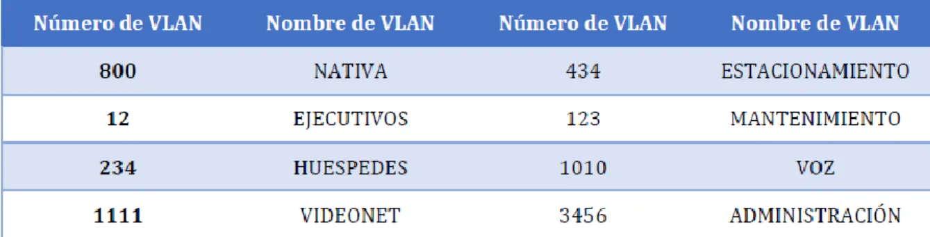
2.6 Configurar en el servidor principal las siguientes VLAN:
Tabla 1. VLAN asignada para creación
Se procede a configurar las VLAN indicadas en el Servidor, es decir DLS1
DLS1(config)#vlan 800
DLS1(config-vlan)#name native
DLS1(config-vlan)#vlan 12
DLS1(config-vlan)#name Ejecutivos
DLS1(config-vlan)#vlan 234
DLS1(config-vlan)#vlan 1111
VLAN_CREATE_FAIL: Failed to create VLANs 1111 : extended VLAN(s) not allowed in current VTP mode
DLS1(config)#vlan 111 DLS1(config-vlan)#name Videonet DLS1(config-vlan)#vlan 434 DLS1(config-vlan)#name Estacionamiento DLS1(config-vlan)#vlan 123 DLS1(config-vlan)#name Mantenimiento DLS1(config-vlan)#vlan 1010
VLAN_CREATE_FAIL: Failed to create VLANs 1010 : extended VLAN(s) not allowed in current VTP mode
DLS1(config)#101
^
% Invalid input detected at '^' marker.
DLS1(config)#vlan 101
DLS1(config-vlan)#name Voz
DLS1(config-vlan)#vlan
^
% Invalid input detected at '^' marker.
DLS1(config-vlan)#vlan 3456
VLAN_CREATE_FAIL: Failed to create VLANs 3456 : extended VLAN(s) not allowed in current VTP mode
DLS1(config)#vlan 345
DLS1(config-vlan)#name Administracion
Figura 29. Verificación creación de VLAN en DLS1
Figura 31. Modos de operación VTP en DLS1
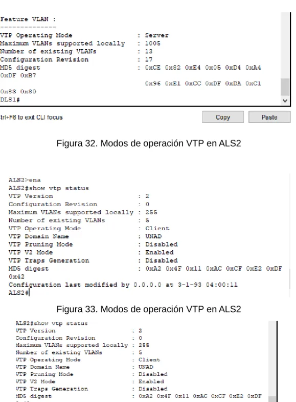
Figura 32. Modos de operación VTP en ALS2
Figura 34 . Modos de operación VTP en ALS1
Figura 36. Modos de operación VTP en ALS1
2.7 En DLS1, suspender la VLAN 434.
Para la suspensión de la VLAN se utiliza el comando state suspend, pero al no permitir el comando packet tracer se procede a negar el comando de vlan así:
DLS1(config-vlan)#vlan 434
DLS1(config-vlan)#?
VLAN configuration commands:
exit Apply changes, bump revision number, and exit mode
name Ascii name of the VLAN
no Negate a command or set its defaults
remote-span Add the Remote Switched Port Analyzer (RSPAN) feature to the VLAN
DLS1(config-vlan)#exit
DLS1(config)#no vlan 434
DLS1(config)#
2.8 Configurar DLS2 en modo VTP transparente VTP utilizando VTP versión 2, y configurar en DLS2 las mismas VLAN que en DLS1.
DLS2#config
Configuring from terminal, memory, or network [terminal]? t
Enter configuration commands, one per line. End with CNTL/Z.
DLS2(config)#vtp mode ?
client Set the device to client mode.
server Set the device to server mode.
transparent Set the device to transparent mode.
DLS2(config)#vtp mode transparent
Setting device to VTP TRANSPARENT mode.
DLS2(config)#vtp domain
% Incomplete command.
DLS2(config)#vtp domain UNAD
Changing VTP domain name from NULL to UNAD
DLS2(config)#vtp pass cisco123
Setting device VLAN database password to cisco123
DLS2(config)#
Configuración de VLAN en DLS2
DLS2(config-vlan)#vlan 434
DLS2(config-vlan)#name Estacionamiento
DLS2(config-vlan)#vlan 123
DLS2(config-vlan)#name Mantenimiento
DLS2(config-vlan)#vlan 101
DLS2(config-vlan)#name Voz
DLS2(config-vlan)#vlan 345
DLS2(config-vlan)#name Administracion
DLS2(config-vlan)#
2.9 Suspender VLAN 434 en DLS2.
DLS2(config)#no vlan 434
DLS2(config)#
2.10 En DLS2, crear VLAN 567 con el nombre de CONTABILIDAD. La VLAN de CONTABILIDAD no podrá estar disponible en cualquier otro Switch de la red.
DLS2(config)#vlan 567
DLS2(config-vlan)#name Contabilidad
DLS2(config-vlan)#
Se realiza la siguiente configuración para DLS1:
DLS1>ena
DLS1#config t
Enter configuration commands, one per line. End with CNTL/Z.
DLS1(config)#sp
DLS1(config)#spanning-tree vlan 1,12,434,800,101,111,345
DLS1(config)#spanning-tree vlan 1,12,434,800,101,111,345 root primary
DLS1(config)#spanning-tree vlan 123,234 root secondary
DLS1(config)#
2.12 Configurar DLS2 como Spanning tree root para las VLAN 123 y 234 y como una raíz secundaria para las VLAN 12, 434, 800, 1010, 1111 y 3456.
DLS2#config t
Enter configuration commands, one per line. End with CNTL/Z.
DLS2(config)#sp
DLS2(config)#spanning-tree vlan 123,234 root primary
DLS2(config)#s
DLS2(config)#s`pa
DLS2(config)#sp
DLS2(config)#spanning-tree vlan 12,434,800,101,111,345 root secondary
DLS2(config)#
Se realiza mediante el ingreso del comando
Switchport trunk encapsulation dot1q
Switchport trunk native vlan 800
Switchport mode trunk
Switchport nonegotiate
2.14 Configurar las siguientes interfaces como puertos de acceso, asignados a las VLAN de la siguiente manera:
Tabla 2. Asignación de puertos a VLAN
DLS1(config-if-range)#
DLS1(config-if-range)#exit
DLS1(config)#int g1/0/6
DLS1(config-if)#switchport mode access
DLS1(config-if)#switchport acc vlan 345
DLS1(config-if)#int g1/0/15
DLS1(config-if)#switchport mode acc
DLS1(config-if)#switchport acc vlan 111
DLS2>ena
DLS2#config t
Enter configuration commands, one per line. End with CNTL/Z.
DLS2(config)#int g1/0/6
DLS2(config-if)#swi acc vlan 12
DLS2(config-if)#swi acc vlan 101
DLS2(config-if)#int g1/0/15
DLS2(config-if)#switchpor mode acc
DLS2(config-if)#swi acc vlan 111
DLS2(config-if)#int g1/0/16-18
^
% Invalid input detected at '^' marker.
DLS2(config-if)#int g1/0/16
DLS2(config-if)#switchpor mode acc
DLS2(config-if)#swi acc vlan 567
DLS2(config-if)#int g1/0/18
DLS2(config-if)#switchpor mode acc
DLS2(config-if)#swi acc vlan 567
DLS2(config-if)#
ALS1#!^Z
ALS1#!^Z
ALS1#config t
Enter configuration commands, one per line. End with CNTL/Z.
ALS1(config)#int fa0/6
ALS1(config-if)#switch mode acc
ALS1(config-if)#sw acc vlan 123
ALS1(config-if)#sw acc vlan 1010
ALS1(config-if)#int fa0/15
ALS1(config-if)#no sw acc vlan 123
ALS1(config-if)#switch mode acc
ALS1(config-if)#no sw acc vlan 1111
ALS1(config-if)#
ALS2>ena
ALS2#config t
Enter configuration commands, one per line. End with CNTL/Z.
ALS2(config)#int fa0/6
ALS2(config-if)#swi mode acc
ALS2(config-if)#sw ac vlan 234
ALS2(config-if)#int fa0/15
ALS2(config-if)#swi mode acc
ALS2(config-if)#sw ac vlan 1111
ALS2(config-if)#
Parte 2: conectividad de red de prueba y las opciones configuradas.
Figura 37. Resultado comando show vlan brief para DLS1
2.16 Verificar que el EtherChannel entre DLS1 y ALS1 está configurado correctamente
Figura 47. Configuración EtherChannel ALS1
2.17 Verificar la configuración de Spanning tree entre DLS1 o DLS2 para cada VLAN.
CONCLUSIONES
Al utilizar la tecnología EtherChannel que se basa en el estándar IEEE 802.3
mediante agrupación múltiple, es posible su uso en los lugares de la red donde se
presenten cuellos de botella, gracias a que permiten un crecimiento escalable y a
medidad, además es posible que se modifique el ancho de banda para su aumento
en cualquiera de los enlaces en donde se tiene configurado el EtherChannel. De
igual forma, esta tecnología cumple la siguiente función: cuando un enlace falla,
se redirige el tráfico de la red por otros enlaces de recuperación que serán
transparentes para el paquete.
Las tecnologías EtherChannel se encuentran disponibles para todas las
velocidades de los enlaces Ethernet, y permiten que los administradores
desplieguen sus redes de manera escalable para mayor cobertura. Poseen
compatibilidad con las VLAN configuradas y las tecnologías de enrutamiento.
Existen dos protocolos configurables: PAgP en el que los paquetes se
intercambian entre los switch a través de los enlaces configurados para ello, y el
LACP, en donde funciona de manera similar pero difiere en que se asignan roles
a cada uno de los extremos basados en la prioridad del sistema.
El protocolo OSPF se basa en la tecnología de estado de link, permite mayor
balanceo de carga, tiene mejor convergencia que otros protocolos como RIP pues
los cambios se propagan de manera instantánea. Así mismo permite la
autenticación a través del ruteo por medio de diferentes métodos de autenticación
por contraseña y no hay limitación en el conteo de saltos. Utiliza un algoritmo con
el que construye y calcula el recorrido más corto hacia sus destinos conocidos, el
BIBLIOGRAFÍA
Froom, R., Frahim, E. (2015). CISCO Press (Ed). Fundamentals Review. Implementing Cisco IP Switched Networks (SWITCH) Foundation Learning Guide CCNP SWITCH 300-115. Recuperado de https://1drv.ms/b/s!AmIJYei- NT1IlnWR0hoMxgBNv1CJ
Froom, R., Frahim, E. (2015). CISCO Press (Ed). InterVLAN Routing. Implementing Cisco IP Switched Networks (SWITCH) Foundation Learning Guide CCNP SWITCH 300-115. Recuperado de https://1drv.ms/b/s!AmIJYei-NT1IlnWR0hoMxgBNv1CJ
Froom, R., Frahim, E. (2015). CISCO Press (Ed). Spanning Tree Implementation. Implementing Cisco IP Switched Networks (SWITCH) Foundation Learning Guide CCNP SWITCH 300-115. Recuperado de https://1drv.ms/b/s!AmIJYei- NT1IlnWR0hoMxgBNv1CJ
LACP/PAgP (2013). Recuperado de
https://networkingcontrol.wordpress.com/2013/05/12/lacppagp/
RosBarbosa (2016).- Recuperado de https://www.seaccna.com/etherchannel-link- aggregation/
Teare, D., Vachon B., Graziani, R. (2015). CISCO Press (Ed). Basic Network and Routing Concepts. Implementing Cisco IP Routing (ROUTE) Foundation Learning Guide CCNP ROUTE 300-101. Recuperado de https://1drv.ms/b/s!AmIJYei- NT1IlnMfy2rhPZHwEoWx
Teare, D., Vachon B., Graziani, R. (2015). CISCO Press (Ed). EIGRP Implementation. Implementing Cisco IP Routing (ROUTE) Foundation Learning Guide CCNP ROUTE 300-101. Recuperado de https://1drv.ms/b/s!AmIJYei- NT1IlnMfy2rhPZHwEoWx
Teare, D., Vachon B., Graziani, R. (2015). CISCO Press (Ed). Manipulating Routing Updates. Implementing Cisco IP Routing (ROUTE) Foundation Learning Guide CCNP ROUTE 300-101. Recuperado de