Prueba de Habilidades Practicas CCNP
(Autor)
Edwin Alejandro Rodríguez Quevedo
Programa Ingeniería de Telecomunicaciones
Departamento de Ingeniería
Universidad Nacional Abierta y a Distancia
Prueba de Habilidades Practicas CCNP
(Autor) Edwin Alejandro Rodríguez Quevedo
Trabajo de grado presentado como requisito para optar al título de Ingeniero de Telecomunicaciones
Director: Gerardo Granados Acuña Magíster en Telemática
Universidad Nacional Abierta y a Distancia
3 Dedicatoria
Este trabajo de grado se lo dedico a Dios quien día a día me permite vivir y me da sabiduría para afrontar cada situación de la vida, a mi madre quien sin tener muchos recursos me formó con grandes valores que me permiten hoy en día conseguir cada una de mis metas.
4
Agradecimientos
El desarrollo de este trabajo de grado a significado mucho esfuerzo por parte de quienes tenemos el compromiso y el requisito para optar por el título de Ingeniero.
Sin embargo, el resultado no hubiese sido posible sin contar con la colaboración de varias personas que apoyaron este proceso.
Primeramente, a Dios que me da la salud, la inteligencia, el valor para afrontar cada reto en mi vida, a mi esposa y mis hijos que sin importar el tiempo que tuve que sacrificar siempre estuvieron ahí dándome fuerzas para continuar, a la Universidad por el apoyo en la formación que estamos recibiendo que nos cualifica cada vez más para asumir los retos de una Institución con un alto grado de conocimiento.
5
Tabla de contenido
1. Introducción ... 8
2. Objetivos ... 9
2.1 Objetivo general ... 9
2.2 Objetivos específicos ... 9
3. Evaluación – prueba de habilidades practicas CCNP ... 10
3.1 Escenario 1 ... 10
3.2 Escenario 2 ... 32
4. Conclusiones ... 77
6
Lista de ilustraciones
Ilustración 1: Topología Escenario 1 ... 10
Ilustración 2: Configuración Interfaces R1 ... 11
Ilustración 3: Configuración Interfaces R2 ... 13
Ilustración 4: Configuración Interfaces R3 ... 14
Ilustración 5: Configuración OSPFV3 R2 ... 14
Ilustración 6: Configuración OSPFV3 R3 ... 15
Ilustración 7: Configuración OSPF en las Interfaces en R2 ... 15
Ilustración 8: Configuración OSPF en las Interfaces en R3 ... 16
Ilustración 9: Configuración área 1 como totalmente Stubby en R2 ... 17
Ilustración 10: Propagación rutas por defecto de IPv4 y IPv6 en R3 ... 17
Ilustración 11: Configuración interfaces pasivas para EIGRP en R1 ... 18
Ilustración 12: Configuración del protocolo EIGRP en R2 ... 19
Ilustración 13: Configuración sistema autónomo R2 ... 20
Ilustración 14: Configuración Métricas y redistribución de Protocolo en R2 ... 21
Ilustración 15: Creación de ACL en R2 ... 21
Ilustración 16: Redistribución R2 ... 22
Ilustración 17: Tabla enrutamiento R1 ... 22
Ilustración 18: Tabla enrutamiento R2 ... 23
Ilustración 19: Tabla enrutamiento IPV6 R2 ... 24
Ilustración 20: Tabla enrutamiento R3 ... 26
Ilustración 21: Prueba de ping IPV4 R1 ... 26
Ilustración 22: Prueba de ping IPV6 R1 ... 27
Ilustración 23: Prueba de ping IPV4 R2 ... 27
Ilustración 24: Prueba de ping IPV4 R3 ... 28
Ilustración 25: Prueba de ping IPV6 R3 ... 28
Ilustración 26: Prueba de ping IPV6 R2 ... 29
Ilustración 27: Configuración Interfaces y Protocolo en R1 ... 30
Ilustración 28: Configuración Interfaces y Protocolo en R2 ... 31
Ilustración 29: Configuración Interfaces y Protocolo en R3 ... 31
Ilustración 30: Topología Escenario 2 ... 32
Ilustración 31: Verificación Interfaces en DLS1 ... 33
Ilustración 32: Verificación Interfaces en DLS2 ... 33
Ilustración 33: Verificación Interfaces en ALS1 ... 34
Ilustración 34: Verificación Interfaces en ALS2 ... 34
Ilustración 35: Cambiar nombre a los equipos. ... 35
Ilustración 36: Configuración de PortChannel en DLS1 ... 35
Ilustración 37: Configuración de PortChannel en DLS2 ... 36
Ilustración 38: Configuración LACP en DLS1 ... 36
Ilustración 39: Configuración LACP en ALS1 ... 37
Ilustración 40: Configuración LACP en DLS12 ... 37
7
Ilustración 42: Configuración PAgP en DLS1 ... 38
Ilustración 43: Configuración PAgP en ALS2 ... 39
Ilustración 44: Configuración PAgP en DLS2 ... 39
Ilustración 45: Configuración PAgP en ALS1 ... 40
Ilustración 46: Validación de vlan Nativa actual en puertos troncales... 40
Ilustración 47: Validación nueva vlan Nativa puertos troncales DLS1 ... 41
Ilustración 48: Validación nueva vlan Nativa puertos troncales DLS2 ... 41
Ilustración 49: Validación nueva vlan Nativa puertos troncales ALS2 ... 41
Ilustración 50: Validación nueva vlan Nativa puertos troncales ALS1 ... 42
Ilustración 51: Validación del estatus del VTP en DLS1 ... 42
Ilustración 52: Validación del estatus del VTP en ALS1 ... 43
Ilustración 53: Validación del estatus del VTP en ALS2 ... 43
Ilustración 54: Verificación de vlan creadas en DLS1 ... 44
Ilustración 55: Verificación de vlan creadas en DLS2 ... 45
Ilustración 56: Validación de configuración en DLS2 ... 46
Ilustración 57: Configuración de STP en DLS1 ... 47
Ilustración 58: Configuración de STP en DLS2 ... 47
Ilustración 59: Validación de configuración en DLS1 ... 47
Ilustración 60: Validación de configuración en DLS2 ... 48
Ilustración 61: Validación de configuración en ALS1 ... 48
Ilustración 62: Validación de configuración en ALS2 ... 49
Ilustración 63: Configuración puertos de Acceso ... 50
Ilustración 64: Validación estado de interfaces DLS1 ... 51
Ilustración 65: Validación estado de interfaces DLS2 ... 51
Ilustración 66: Validación estado de interfaces ALS1 ... 52
Ilustración 67: Validación estado de interfaces ALS2 ... 52
Ilustración 68: Verificación vlan Interface DLS1 ... 53
Ilustración 69: Verificación vlan Interface DLS2 ... 53
Ilustración 70: Validación LoopBack DLS1 - DLS2 ... 54
Ilustración 71: Obtención de IP por DHCP Host A ... 60
Ilustración 72: Obtención de IP por DHCP Host B ... 61
Ilustración 73: Obtención de IP por DHCP Host D ... 62
Ilustración 74: Verificación vlan propagadas ALS1 ... 62
Ilustración 75: Verificación vlan propagadas ALS2 ... 63
Ilustración 76: Verificación vlan propagadas DLS1 ... 63
Ilustración 77: Verificación vlan propagadas DLS2 ... 64
Ilustración 78: Validación Ether Channel DLS1 ... 64
8
1. Introducción
El presente trabajo sustenta de manera escrita y gráfica el proceso que se ha realizado para implementar cada uno de los temas vistos durante el desarrollo del curso CCNP de Cisco, en equipos Router y Switches. El caso propuesto para Routing fue desarrollado en la plataforma GNS3 2.1.4 y el caso para Switching fue desarrollado en la plataforma PacketTracert 7.1. En la guía estipulada se indicaba realizar algún caso de estudio en la plataforma Online Smartlab, pero al tratar de realizar cada una de las configuraciones necesarias, no se logra cumplir con cada uno de los objetivos, por lo cual se toma la decisión de no usarla, teniendo en cuenta que la idea es aprender al máximo la implementación de cada uno de los protocolos y parámetros que podemos configurar en cada uno de los equipos que podemos encontrar en un ambiente laboral.
A continuación, se relacionan los temas que se abordaran durante la resolución de cada caso de estudio de acuerdo al problema planteado:
Routing:
• Configuración de enlaces seriales.
• Configuración del protocolo OSPFv3 para IPV4 e IPV6. • Áreas Stubby.
• Propagación de rutas por defecto.
• Configuración del protocolo EIGRP para IPV4 e IPV6. • Redistribución de protocolos.
• Listas de distribución y ACL.
Switching:
• Configuración de puertos troncales y de Acceso.
• Configuración de interfaces Port-channel capa 2 y capa 3. • Implementación de VTP para propagación de vlan.
• Creación de vlan.
• Implementación de STP (Spanning Tree Protocol).
• Configuración de SVI (Switch Virtual Interface) y enrutamiento entre vlan. • Configuración de interfaces Loopback.
9 2. Objetivos
2.1 Objetivo general
Dar solución a cada uno de los casos de estudio planteados indicando y aplicando los comandos necesarios para realizar cada una de las configuraciones requeridas de acuerdo a lo aprendido durante el desarrollo del curso.
2.2 Objetivos específicos
• Investigar y analizar cada uno de los temas requeridos para dar solución al problema planteado.
• Configurar cada uno de los equipos necesarios para la implementación de cada caso de estudio propuesto.
• Conocer y aplicar los comandos necesarios para establecer los parámetros que cada protocolo requiere para su funcionamiento.
10
3. Evaluación – prueba de habilidades practicas CCNP
Descripción de escenarios propuestos para la prueba de habilidades
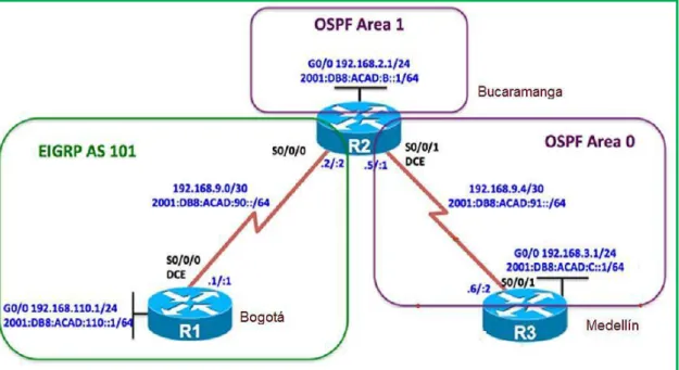
3.1 Escenario 1
Una empresa de confecciones posee tres sucursales distribuidas en las ciudades de Bogotá, Medellín y Bucaramanga, en donde el estudiante será el administrador de la red, el cual deberá configurar e interconectar entre sí cada uno de los dispositivos que forman parte del escenario, acorde con los lineamientos establecidos para el direccionamiento ip, protocolos de enrutamiento y demás aspectos que forman parte de la topología de red.
Topología de red
Configurar la topología de red, de acuerdo con las siguientes especificaciones. Parte 1: Configuración del escenario propuesto
1. Configurar las interfaces con las direcciones IPv4 e IPv6 que se muestran en la topología de red.
2. Ajustar el ancho de banda a 128 kbps sobre cada uno de los
enlaces seriales ubicados en R1, R2, y R3 y ajustar la velocidad de reloj de las conexiones de DCE según sea apropiado.
Para esto usamos los siguientes comandos en R1, R2 y en R3:
11 Router#
Router#configure terminal Router(config)#hostname R1 R1(config)#ipv6 unicast-routing R1(config)#interface FastEthernet0/0
R1(config-if)#ip address 192.168.110.1 255.255.255.0 R1(config-if)#ipv6 address 2001:db8:acad:110::1/64 R1(config-if)#no shutdown
R1(config-if)#
*May 22 23:07:08.471: %LINK-3-UPDOWN: Interface FastEthernet0/0, changed state to down
R1(config-if)#interface serial1/0
R1(config-if)#ip address 192.168.9.1 255.255.255.0 R1(config-if)#ipv6 address 2001:db8:acad:90::1/64 R1(config-if)#clock rate 128000
R1(config-if)#bandwidth 128 R1(config-if)#no shutdown R1(config-if)#
*May 22 23:07:37.859: %LINK-3-UPDOWN: Interface Serial1/0, changed state to up
R1(config-if)#
*May 22 23:07:38.871: %LINEPROTO-5-UPDOWN: Line protocol on Interface Serial1/0, changed state to up
R1(config-if)#
*May 22 23:08:02.067: %LINEPROTO-5-UPDOWN: Line protocol on Interface Serial1/0, changed state to down
R1(config-if)#
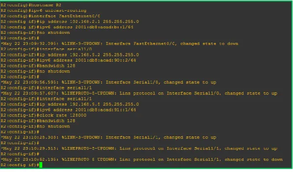
12 Configuración parámetros R2:
Router(config)#hostname R2 R2(config)#ipv6 unicast-routing R2(config)#interface FastEthernet0/0
R2(config-if)#ip address 192.168.2.1 255.255.255.0 R2(config-if)#ipv6 address 2001:db8:acad:b::1/64 R2(config-if)#no shutdown
R2(config-if)#
*May 22 23:09:32.095: %LINK-3-UPDOWN: Interface FastEthernet0/0, changed state to down
R2(config-if)#interface serial1/0
R2(config-if)#ip address 192.168.9.2 255.255.255.0 R2(config-if)#ipv6 address 2001:db8:acad:90::2/64 R2(config-if)#bandwidth 128
R2(config-if)#no shutdown R2(config-if)#
*May 22 23:09:56.595: %LINK-3-UPDOWN: Interface Serial1/0, changed state to up
R2(config-if)#interface serial1/1
*May 22 23:09:57.607: %LINEPROTO-5-UPDOWN: Line protocol on Interface Serial1/0, changed state to up
R2(config-if)#interface serial1/1
R2(config-if)#ip address 192.168.9.5 255.255.255.0 R2(config-if)#ipv6 address 2001:db8:acad:91::1/64 R2(config-if)#clock rate 128000
R2(config-if)#bandwidth 128 R2(config-if)#no shutdown R2(config-if)#
*May 22 23:10:28.303: %LINK-3-UPDOWN: Interface Serial1/1, changed state to up
R2(config-if)#
*May 22 23:10:29.315: %LINEPROTO-5-UPDOWN: Line protocol on Interface Serial1/1, changed state to up
R2(config-if)#
*May 22 23:10:52.135: %LINEPROTO-5-UPDOWN: Line protocol on Interface Serial1/1, changed state to down
13
Ilustración 3: Configuración Interfaces R2
Configuración parámetros R3
Router#configure terminal Router(config)#hostname R3 R3(config)#ipv6 unicast-routing R3(config)#interface FastEthernet0/0
R3(config-if)#ip address 192.168.3.1 255.255.255.0 R3(config-if)#ipv6 address 2001:db8:acad:c::1/64 R3(config-if)#no shutdown
R3(config-if)#
*May 22 23:12:16.963: %LINK-3-UPDOWN: Interface FastEthernet0/0, changed state to down
R3(config-if)#interface serial1/0
R3(config-if)#ip address 192.168.9.6 255.255.255.0 R3(config-if)#ipv6 address 2001:db8:acad:91::2/64 R3(config-if)#bandwidth 128
R3(config-if)#no shutdown R3(config-if)#
*May 22 23:12:55.587: %LINK-3-UPDOWN: Interface Serial1/0, changed state to up
R3(config-if)#
*May 22 23:12:56.599: %LINEPROTO-5-UPDOWN: Line protocol on Interface Serial1/0, changed state to up
14
Ilustración 4: Configuración Interfaces R3
3. En R2 y R3 configurar las familias de direcciones OSPFv3 para IPv4 e IPv6. Utilice el identificador de enrutamiento 2.2.2.2 en R2 y
3.3.3.3 en R3 para ambas familias de direcciones.
Procedemos a configurar el protocolo aplicando los siguientes comandos:
R2(config-if)#router ospfv3 1
R2(config-router)#address-family ipv4 unicast R2(config-router-af)#router-id 2.2.2.2
R2(config-router-af)#exit-address-family R2(config-router)#address-family ipv6 unicast R2(config-router-af)#router-id 2.2.2.2
R2(config-router-af)#exit-address-family R2(config-router)#
Ilustración 5: Configuración OSPFV3 R2
R3(config-if)#router ospfv3 1
R3(config-router)#address-family ipv4 unicast R3(config-router-af)#router-id 3.3.3.3
R3(config-router-af)#passive-interface FastEthernet0/0 R3(config-router-af)#exit-address-family
R3(config-router)#address-family ipv6 unicast R3(config-router-af)#router-id 3.3.3.3
15 R3(config-router-af)#exit-address-family R3(config-router)#
Ilustración 6: Configuración OSPFV3 R3
4. En R2, configurar la interfaz F0/0 en el área 1 de OSPF y la conexión serial entre R2 y R3 en OSPF área 0.
Configuramos OSPF en la interface indicada.
R2(config)#interface FastEthernet0/0 R2(config-if)#ospfv3 1 ipv4 area 1 R2(config-if)#ospfv3 1 ipv6 area 1 R2(config-if)#interface serial1/1 R2(config-if)#ospfv3 1 ipv4 area 0 R2(config-if)#ospfv3 1 ipv6 area 0 R2(config-if)#
*May 22 23:17:16.215: %OSPFv3-5-ADJCHG: Process 1, IPv4, Nbr 3.3.3.3 on Serial1/1 from LOADING to FULL, Loading Done
R2(config-if)#
*May 22 23:17:18.095: %OSPFv3-5-ADJCHG: Process 1, IPv6, Nbr 3.3.3.3 on Serial1/1 from LOADING to FULL, Loading Done
R2(config-if)#
Ilustración 7: Configuración OSPF en las Interfaces en R2
16 R3(config)#interface FastEthernet0/0 R3(config-if)#ospfv3 1 ipv4 area 0 R3(config-if)#ospfv3 1 ipv6 area 0 R3(config-if)#interface serial1/0 R3(config-if)#ospfv3 1 ipv4 area 0 R3(config-if)#ospfv3 1 ipv6 area 0
*May 22 23:17:15.883: %OSPFv3-5-ADJCHG: Process 1, IPv4, Nbr 2.2.2.2 on Serial1/0 from LOADING to FULL, Loading Done
R3(config-if)#ospfv3 1 ipv6 area 0 R3(config-if)#
*May 22 23:17:17.755: %OSPFv3-5-ADJCHG: Process 1, IPv6, Nbr 2.2.2.2 on Serial1/0 from LOADING to FULL, Loading Done
R3(config-if)#
Ilustración 8: Configuración OSPF en las Interfaces en R3
6. Configurar el área 1 como un área totalmente Stubby.
Procedemos a configurar un área Stubby.
R2#configure terminal
Enter configuration commands, one per line. End with CNTL/Z. R2(config)#router ospfv3 1
17
Ilustración 9: Configuración área 1 como totalmente Stubby en R2
7. Propagar rutas por defecto de IPv4 y IPv6 en R3 al interior del dominio OSPFv3.
Nota: Es importante tener en cuenta que una ruta por defecto es diferente a la definición de rutas estáticas.
R3#configure terminal
Enter configuration commands, one per line. End with CNTL/Z. R3(config)#router ospfv3 1
R3(config-router)#address-family ipv4 unicast
R3(config-router-af)#default-information originate always R3(config-router-af)#exit-address-family
R3(config-router)#address-family ipv6 unicast
R3(config-router-af)#default-information originate always R3(config-router-af)#exit-address-family
R3(config-router)#
Ilustración 10: Propagación rutas por defecto de IPv4 y IPv6 en R3
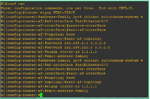
8. Realizar la configuración del protocolo EIGRP para IPv4 como IPv6. Configurar la interfaz F0/0 de R1 y la conexión entre R1 y R2 para EIGRP con el sistema autónomo 101. Asegúrese de que el resumen automático está desactivado.
18 R1#conf ter
Enter configuration commands, one per line. End with CNTL/Z. R1(config)#router eigrp DUAL-STACK
R1(config-router)#address-family ipv4 unicast autonomous-system 4 R1(config-router-af)#af-interface FastEthernet0/0
R1(config-router-af-interface)#passive-interface R1(config-router-af-interface)#exit-af-interface R1(config-router-af)#topology base
R1(config-router-af-topology)#exit-af-topology R1(config-router-af)#network 192.168.9.0 0.0.0.3 R1(config-router-af)#network 192.168.110.0 0.0.0.3 R1(config-router-af)#eigrp router-id 1.1.1.1
R1(config-router-af)#exit-address-family
R1(config-router)#address-family ipv6 unicast autonomous-system 6 R1(config-router-af)#af-interface FastEthernet0/0
R1(config-router-af-interface)#passive-interface R1(config-router-af-interface)#exit-af-interface R1(config-router-af)#topology base
R1(config-router-af-topology)#exit-af-topology R1(config-router-af)#eigrp router-id 1.1.1.1 R1(config-router-af)#exit-address-family
Ilustración 11: Configuración interfaces pasivas para EIGRP en R1
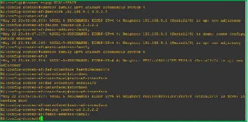
R2(config)#router eigrp DUAL-STACK
19 R2(config-router-af)#
*May 22 23:43:35.639: %DUAL-5-NBRCHANGE: EIGRP-IPv4 4: Neighbor 192.168.9.1 (Serial1/0) is up: new adjacency
R2(config-router-af)#eigrp router-id 2.2.2.2 R2(config-router-af)#exit-address-family
*May 22 23:44:07.087: %DUAL-5-NBRCHANGE: EIGRP-IPv4 4: Neighbor 192.168.9.1 (Serial1/0) is down: route configuration changed
*May 22 23:44:08.043: %DUAL-5-NBRCHANGE: EIGRP-IPv4 4: Neighbor 192.168.9.1 (Serial1/0) is up: new adjacency
R2(config-router-af)#exit-address-family
R2(config-router)#address-family ipv6 unicast autonomous-system 6 R2(config-router-af)#
*May 22 23:44:22.819: %DUAL-5-NBRCHANGE: EIGRP-IPv6 6: Neighbor FE80::C801:1DFF:FE84:0 (Serial1/0) is up: new adjacency
R2(config-router-af)#af-interface FastEthernet0/0 R2(config-router-af-interface)#shutdown
R2(config-router-af-interface)#exit-af-interface R2(config-router-af)#af-interface serial1/0 R2(config-router-af-interface)#shutdown R2(config-router-af-interface)#exit-af-interface
*May 22 23:45:16.807: %DUAL-5-NBRCHANGE: EIGRP-IPv6 6: Neighbor FE80::C801:1DFF:FE84:0 (Serial1/0) is down: interface down
R2(config-router-af-interface)#exit-af-interface R2(config-router-af)#eigrp router-id 2.2.2.2 R2(config-router-af)#exit-address-family R2(config-router)#
Ilustración 12: Configuración del protocolo EIGRP en R2
R2#conf ter
Enter configuration commands, one per line. End with CNTL/Z. R2(config)#router eigrp DUAL-STACK
20
R2(config-router)#address-family ipv4 unicast autonomous-system 4 R2(config-router-af)#topology base
R2(config-router-af-topology)#distribute-list R3-to-R1 out R2(config-router-af-topology)#
*May 17 23:15:41.471: %DUAL-5-NBRCHANGE: EIGRP-IPv4 4: Neighbor 192.168.9.1 (Serial2/0) is resync: route configuration changed
R2(config-router-af-topology)#redistribute ospfv3 1 metric 10000 100 255 1 1500
R2(config-router-af-topology)#exit-af-topology R2(config-router-af)#
Ilustración 13: Configuración sistema autónomo R2
10. En R2, configurar la redistribución mutua entre OSPF y EIGRP para IPv4 e IPv6. Asignar métricas apropiadas cuando sea necesario.
Realizamos redistribución en los protocolos OSPF y EIGRP.
R2#conf ter
Enter configuration commands, one per line. End with CNTL/Z. R2(config)#router eigrp DUAL-STACK
R2(config-router)#address-family ipv4 unicast autonomous-system 4 R2(config-router-af)#topology base
R2(config)#distribute-list R3-to-R1 out
R2(config-router-af-topology)#redistribute ospfv3 1 metric 10000 100 255 1 1500 R2(config-router-af-topology)#exit-af-topology
R2(config-router)#address-family ipv6 unicast autonomous-system 6 R2(config-router-af)#topology base
R2(config-router-af-topology)#redistribute ospf 1 metric 10000 100 255 1 1500 R2(config-router-af-topology)#exit-af-topology
21
Ilustración 14: Configuración Métricas y redistribución de Protocolo en R2
11. En R2, de hacer publicidad de la ruta 192.168.3.0/24 a R1 mediante una lista de distribución y ACL.
Configuramos la lista de acceso.
R2(config-router)#ip access-list standard R3-to-R1 R2(config-std-nacl)#remark ACL to filter 192.168.3.0/24 R2(config-std-nacl)#
*May 23 00:05:20.751: %DUAL-5-NBRCHANGE: EIGRP-IPv4 4: Neighbor 192.168.9.1 (Serial1/0) is resync: route configuration changed
R2(config-std-nacl)#deny 192.168.3.0 0.0.0.255 R2(config-std-nacl)#permit any
R2(config-std-nacl)#
*May 23 00:05:48.531: %DUAL-5-NBRCHANGE: EIGRP-IPv4 4: Neighbor 192.168.9.1 (Serial1/0) is resync: route configuration changed
R2(config-std-nacl)#
Ilustración 15: Creación de ACL en R2
R2#conf term
Enter configuration commands, one per line. End with CNTL/Z. R2(config)#router ospfv3 1
R2(config-router)#address-family ipv4 unicast R2(config-router-af)#redistribute eigrp 4
R2(config-router-af)#address-family ipv6 unicast R2(config-router-af)#redistribute eigrp 6
22
Ilustración 16: Redistribución R2
Parte 2: Verificar conectividad de red y control de la trayectoria.
a. Registrar las tablas de enrutamiento en cada uno de los routers, acorde con los parámetros de configuración establecidos en el escenario propuesto.
En las imágenes siguientes podemos observar las tablas de enrutamiento a nivel de IPV4 e IPV6.
23
24
26
Ilustración 20: Tabla enrutamiento R3
b. Verificar comunicación entre routers mediante el comando ping y traceroute.
Procedemos a realizar pruebas de ping en cada uno de los router.
27
Ilustración 22: Prueba de ping IPV6 R1
28
Ilustración 24: Prueba de ping IPV4 R3
29
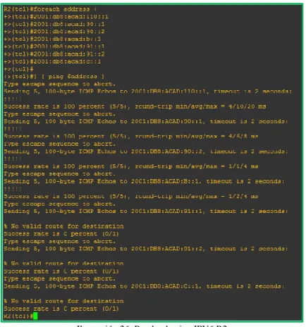
Ilustración 26: Prueba de ping IPV6 R2
Algunas ip´s no responden a ping, esto se debe a la configuración realizada, ya que se configuraron algunas listas de acceso que restringen la comunicación.
c. Verificar que las rutas filtradas no están presentes en las tablas de enrutamiento de los routers correctas.
30
Ilustración 27: Configuración Interfaces y Protocolo en R1
R2#show runn
31
Ilustración 28: Configuración Interfaces y Protocolo en R2
32 3.2 Escenario 2
Una empresa de comunicaciones presenta una estructura Core acorde a la topología de red, en donde el estudiante será el administrador de la red, el cual deberá configurar e interconectar entre sí cada uno de los dispositivos que forman parte del escenario, acorde con los lineamientos establecidos para el direccionamiento IP, EtherChannel, VLANs y demás aspectos que forman parte del escenario propuesto.
Topología de red
Parte 1: Configurar la red de acuerdo con las especificaciones.
a. Apagar todas las interfaces en cada switch.
Para eso ingresamos a cada interface y ejecutamos el comando Shutdown
DLS1(config)#interface Fa0/0 DLS1(config-if)#shutdown DLS1(config-if)#exit DLS1(config)#
33
Ilustración 31: Verificación Interfaces en DLS1
34
Ilustración 33: Verificación Interfaces en ALS1
Ilustración 34: Verificación Interfaces en ALS2
b. Asignar un nombre a cada switch acorde al escenario establecido.
Con el siguiente comando cambiamos el nombre a cada uno de los switch.
IOU1(config)#
35 DLS1(config)#
Ilustración 35: Cambiar nombre a los equipos.
c. Configurar los puertos troncales y Port-channels tal como se muestra en el diagrama.
1) La conexión entre DLS1 y DLS2 será un EtherChannel capa-3
utilizando LACP. Para DLS1 se utilizará la dirección IP 10.12.12.1/30 y para DLS2 utilizará 10.12.12.2/30.
Creamos el port channel capa 3 y luego lo asignamos a las interfaces, esto lo debemos hacer en el Router DLS1 y DLS2.
DLS1(config)#inter port-channel 12 DLS1(config-if)#no switchport
DLS1(config-if)#ip address 10.12.12.1 255.255.255.252 DLS1(config-if)#exit
DLS1(config)#inter rang fa0/5-6 DLS1(config-if-range)#no switchport
DLS1(config-if-range)#channel-group 12 mode active
Para validar el estado del Etherchannel usamos el comando: DLS1#show etherchannel summary
36
Ilustración 37: Configuración de PortChannel en DLS2
2) Los Port-channels en las interfaces Fa0/7 y Fa0/8 utilizarán LACP.
Para etherchannel capa 2 LACP usamos los siguientes comandos:
DLS1(config)#int ran fa0/1-2
DLS1(config-if-range)# switchport trunk encapsulation dot1q DLS1(config-if-range)# switchport mode trunk
DLS1(config-if-range)#channel-group 1 mode active Creating a port-channel interface Port-channel 1 DLS1(config-if-range)#no shutdown
Ilustración 38: Configuración LACP en DLS1
ALS1(config)#int ran fa0/1-2
ALS1(config-if-range)# switchport trunk encapsulation dot1q ALS1(config-if-range)# switchport mode trunk
37
Creating a port-channel interface Port-channel 1 ALS1(config-if-range)#no shutdown
Ilustración 39: Configuración LACP en ALS1
DLS2(config)#int ran fa0/1-2
DLS2(config-if-range)# switchport trunk encapsulation dot1q DLS2(config-if-range)# switchport mode trunk
DLS2(config-if-range)#channel-group 2 mode active Creating a port-channel interface Port-channel 2 DLS2(config-if-range)#no shutdown
Ilustración 40: Configuración LACP en DLS12
ALS2(config)#int ran fa0/1-2
ALS2(config-if-range)# switchport trunk encapsulation dot1q ALS2(config-if-range)# switchport mode trunk
38
Ilustración 41: Configuración LACP en ALS2
3) Los Port-channels en las interfaces F0/9 y fa0/10 utilizará PAgP.
Para etherchannel capa 2 PAgP usamos los siguientes comandos:
DLS1(config)#int ran e0/3-4
DLS1(config-if-range)# switchport trunk encapsulation dot1q DLS1(config-if-range)# switchport mode trunk
DLS1(config-if-range)#channel-group 4 mode desirable Creating a port-channel interface Port-channel 4
DLS1(config-if-range)#no shutdown
Ilustración 42: Configuración PAgP en DLS1
ALS2(config)#int ran e0/3-4
ALS2(config-if-range)# switchport trunk encapsulation dot1q ALS2(config-if-range)# switchport mode trunk
ALS2(config-if-range)#channel-group 4 mode desirable Creating a port-channel interface Port-channel 4
39
Ilustración 43: Configuración PAgP en ALS2
DLS2(config)#int ran e0/3-4
DLS2(config-if-range)# switchport trunk encapsulation dot1q DLS2(config-if-range)# switchport mode trunk
DLS2(config-if-range)#channel-group 3 mode desirable Creating a port-channel interface Port-channel 3
DLS2(config-if-range)#no shutdown
Ilustración 44: Configuración PAgP en DLS2
ALS1(config)#int ran e0/3-4
ALS1(config-if-range)# switchport trunk encapsulation dot1q ALS1(config-if-range)# switchport mode trunk
ALS1(config-if-range)#channel-group 3 mode desirable Creating a port-channel interface Port-channel 3
40
Ilustración 45: Configuración PAgP en ALS1
4) Todos los puertos troncales serán asignados a la VLAN 800 como la VLAN nativa.
Para validar que puertos son troncales usamos el siguiente comando en cada uno de los switches:
DLS1#show interfaces trunk
Ilustración 46: Validación de vlan Nativa actual en puertos troncales
Luego usamos el siguiente comando para asignar la vlan 800 como vlan nativa para todos los puertos troncales en todos los Switches, en nuestro caso son la inerfaces que pertenecen a los pot-channel 1, 2, 3 y 4.
DLS1#conf ter
DLS1(config)#int port-channel 1
DLS1(config-if)#switchport trunk native vlan 800 DLS1(config-if)#exit
41
Luego validamos que las interfaces troncales hayan quedado con la vlan nativa 800.
Ilustración 47: Validación nueva vlan Nativa puertos troncales DLS1
Ilustración 48: Validación nueva vlan Nativa puertos troncales DLS2
42
Ilustración 50: Validación nueva vlan Nativa puertos troncales ALS1
d. Configurar DLS1, ALS1, y ALS2 para utilizar VTP versión 2
1) Utilizar el nombre de dominio UNAD con la contraseña cisco123
DLS1#conf ter
DLS1(config)#vtp doma UNAD
Changing VTP domain name from NULL to UNAD DLS1(config)#vtp pass cisco123
Setting device VLAN database password to cisco123 DLS1(config)#vtp ver 2
DLS1(config)#exit DLS1#
2) Configurar DLS1 como servidor principal para las VLAN.
DLS1(config)#vtp mode server Device mode already VTP SERVER. DLS1(config)#
Para consultar el estado del Vtp usamos el comando Show VTP status.
43
3) Configurar ALS1 y ALS2 como clientes VTP.
Usamos los siguientes comandos:
ALS1#conf ter
Enter configuration commands, one per line. End with CNTL/Z. ALS1(config)#vtp domain UNAD
Domain name already set to UNAD. ALS1(config)#vtp pass cisco123
Setting device VLAN database password to cisco123 ALS1(config)#vtp mode client
Setting device to VTP CLIENT mode. ALS1(config)#vtp ver 2
Cannot modify version in VTP client mode ALS1(config)#exit
ALS1#
Ilustración 52: Validación del estatus del VTP en ALS1
44
e. Configurar en el servidor principal las siguientes VLAN:
Número de VLAN Nombre de VLAN Número de VLAN Nombre de VLAN
800 NATIVA 434 ESTACIONAMIENTO
12 EJECUTIVOS 123 MANTENIMIENTO
234 HUESPEDES 101 VOZ
111 VIDEONET 345 ADMINISTRACIÓN
El Switch no nos permite configurar vlan de mayor rango que 1005 debido a que el VTP solo permite vlan normales y NO extendidas, por lo cual tuvimos que tomar otras vlan para continuar con el laboratorio.
f. En DLS1, suspender la VLAN 434.
DLS1(config)#vlan 434
DLS1(config-vlan)# state suspend DLS1(config)#
Para la versión de Switch que nos proporciona packet tracert 7.1.1, no se puede ejecutar este comando, por lo cual no podemos suspender la vlan. g. Configurar DLS2 en modo VTP transparente VTP utilizando VTP
versión 2, y configurar en DLS2 las mismas VLAN que en DLS1.
DLS2#
DLS2#conf ter
DLS2(config)#vtp domain UNAD
45 Domain name already set to UNAD. DLS2(config)#vtp pass cisco123
Setting device VLAN database password to cisco123 DLS2(config)#vtp mod trans
Setting device to VTP TRANSPARENT mode. DLS2(config)#vtp ver 2
DLS2(config)#exit DLS2#
Ilustración 55: Verificación de vlan creadas en DLS2
h. Suspender VLAN 434 en DLS2.
DLS2(config)#vlan 434
DLS2(config-vlan)# state suspend DLS2(config)#
Para la versión de Switch que nos proporciona packet tracert 7.1.1, no se puede ejecutar este comando, por lo cual no podemos suspender la vlan.
i. En DLS2, crear VLAN 567 con el nombre de CONTABILIDAD. La VLAN de CONTABILIDAD no podrá estar disponible en cualquier otro Switch de la red.
Creamos la vlan
DLS2#conf ter
DLS2(config)#vlan 567
46
Luego en los 2 port-channel troncales negamos el paso de la vlan 567.
DLS2(config)#
DLS2(config)#interface port-channel 2
DLS2(config-if)#switchport trunk allowed vlan except 567 DLS2(config)#interface port-channel 3
DLS2(config-if)#switchport trunk allowed vlan except 567 DLS2(config-if)#end
DLS2#
Ilustración 56: Validación de configuración en DLS2
j. Configurar DLS1 como Spanning tree root para las VLAN 1, 12, 434, 800, 101, 111 y 345 y como raíz secundaria para las VLAN 123 y 234. Asignamos las respectivas vlan como root primary y secondary.
DLS1#conf ter
DLS1(config)#spanning-tree vlan 1,12,434,800,101,111,345 root primary DLS1(config)#spanning-tree vlan 123,234 root secondary
47
Ilustración 57: Configuración de STP en DLS1
k. Configurar DLS2 como Spanning tree root para las VLAN 123 y 234 y como una raíz secundaria para las VLAN 12, 434, 800, 1010, 1111 y 3456.
DLS2#conf ter
DLS2(config)#spanning-tree vlan 123,234 root primary
DLS2(config)#spanning-tree vlan 1,12,434,800,101,111,345 root secondary DLS2(config)#
Ilustración 58: Configuración de STP en DLS2
l. Configurar todos los puertos como troncales de tal forma que solamente las VLAN que se han creado se les permitirá circular a través de estos puertos.
48
Ilustración 60: Validación de configuración en DLS2
49
Ilustración 62: Validación de configuración en ALS2
m. Configurar las siguientes interfaces como puertos de acceso, asignados a las VLAN de la siguiente manera:
Interfaz DLS1
DLS2 ALS1
ALS2
Interfaz Fa0/6 345 12, 101 123, 101 234
Interfaz Fa0/15 111 111 111 111
Interfaces F0 /16-18 567
Usamos el siguiente comando en cada una de las interfaces que conectan cada uno de los hosts y asignando la respectiva vlan según la tabla.
50 DLS1#conf ter
DLS1(config-if)#interface fastEthernet 0/7 DLS1(config-if)#switchport mode access DLS1(config-if)#switchport access vlan 345 DLS1(config-if)#spanning-tree portfast DLS1(config-if)#no shutdown
DLS1(config-if)#
%LINK-5-CHANGED: Interface FastEthernet0/7, changed state to up
%LINEPROTO-5-UPDOWN: Line protocol on Interface FastEthernet0/7, changed state to up
DLS1(config-if)#exit DLS1(config)#
Ilustración 63: Configuración puertos de Acceso
n. Todas las interfaces que no sean utilizadas o asignadas a alguna VLAN deberán ser apagadas.
51
Ilustración 64: Validación estado de interfaces DLS1
52
Ilustración 66: Validación estado de interfaces ALS1
Ilustración 67: Validación estado de interfaces ALS2
o. Configurar SVI en DLS1 y DLS2 como soporte de todas las VLAN y de enrutamiento entre las VLAN. Utilice la siguiente tabla para las
53
VLAN Nombre de
subred VLAN Nombre de VLAN
subred VLAN
12 EJECUTIVOS 10.0.12.0/24 123 MANTENIMIENTO 10.0.123.0/24
234 HUESPEDES 10.0.234.0/24 101 VOZ 10.10.10.0/24
111 VIDEONET 10.11.11.0/24 345 ADMINISTRACIÓN 10.34.56.0/24
• DLS1 siempre utilizará la dirección .252 y DLS2 siempre utilizará la dirección .253 para las direcciones IPv4.
Para crear cada una de las vlan interface, ejecutamos los siguientes comandos tanto en DLS1 como en DLS2, con cada una de las vlan según la tabla.
DLS1#conf ter
DLS1(config)#interface vlan 12
%LINK-5-CHANGED: Interface Vlan12, changed state to up
%LINEPROTO-5-UPDOWN: Line protocol on Interface Vlan12, changed state to up
DLS1(config-if)#ip address 10.0.12.252 255.255.255.0 DLS1(config-if)#no shutdown
DLS1(config-if)#exit DLS1(config)#
Ilustración 68: Verificación vlan Interface DLS1
Ilustración 69: Verificación vlan Interface DLS2
• La VLAN 567 en DLS2 no podrá ser soportada para enrutamiento.
54
Para eso usamos los siguientes comandos tanto en DLS1 como en DLS2.
DLS1#conf ter
DLS1(config)#int loopback 0
%LINK-5-CHANGED: Interface Loopback0, changed state to up
%LINEPROTO-5-UPDOWN: Line protocol on Interface Loopback0, changed state to up
DLS1(config-if)#ip address 1.1.1.1 255.255.255.255 DLS1#
Ilustración 70: Validación LoopBack DLS1 - DLS2
q. Configurar HSRP con interfaz tracking para las VLAN 12, 123, 234, 101, y 111.
1) Utilizar HSRP
2) Crear dos grupos HSRP, alineando VLAN 12, 101, 111, y 345 para el primer grupo y las VLAN 123 y 234 para el segundo grupo.
3) DLS1 será el Switch principal de las VLAN 12, 101, 111, y 345 y DLS2 será el Switch principal para las VLAN 123 y 234.
4) Utilizar la dirección virtual .254 como la dirección de Standby de todas las VLAN
Usamos los siguientes comandos para cada vlan según se requiere.
Debemos tener en cuenta de cambiar la prioridad para el Swith especifico sea principal de algunas vlan según solicitud.
DLS1(config)#
DLS1(config)#interface Vlan 12
DLS1(config-if)# standby 1 ip 10.0.12.254 DLS1(config-if)# standby 1 priority 200 DLS1(config-if)# standby 1 preempt
55
Con el comando Show Standby podemos verificar que las vlan correspondientes hayan quedado Active y las demás Standby.
Se relaciona a continuación el resultado del comando en el Switch DLS1:
DLS1#show standby Vlan12 - Group 1 State is Active
8 state changes, last state change 01:13:13 Virtual IP address is 10.0.12.254
Active virtual MAC address is 0000.0C07.AC01
Local virtual MAC address is 0000.0C07.AC01 (v1 default) Hello time 3 sec, hold time 10 sec
Next hello sent in 2.721 secs Preemption enabled
Active router is local
Standby router is 10.0.12.253 Priority 200 (configured 200)
Track interface FastEthernet0/5 state Up decrement 10 Track interface FastEthernet0/6 state Up decrement 10 Group name is hsrp-Vl1-1 (default)
Vlan234 - Group 2 State is Standby
6 state changes, last state change 01:17:13 Virtual IP address is 10.0.234.254
Active virtual MAC address is 0000.0C07.AC02
Local virtual MAC address is 0000.0C07.AC02 (v1 default) Hello time 3 sec, hold time 10 sec
Next hello sent in 2.617 secs Preemption enabled
Active router is 10.0.234.253, priority 200 (expires in 7 sec) MAC address is 0000.0C07.AC02
Standby router is local Priority 100 (default 100)
Track interface FastEthernet0/5 state Up decrement 10 Track interface FastEthernet0/6 state Up decrement 10 Group name is hsrp-Vl2-2 (default)
Vlan111 - Group 1 State is Active
6 state changes, last state change 01:15:07 Virtual IP address is 10.11.11.254
Active virtual MAC address is 0000.0C07.AC01
Local virtual MAC address is 0000.0C07.AC01 (v1 default) Hello time 3 sec, hold time 10 sec
56 Preemption enabled
Active router is local
Standby router is 10.11.11.253 Priority 200 (configured 200)
Track interface FastEthernet0/5 state Up decrement 10 Track interface FastEthernet0/6 state Up decrement 10 Group name is hsrp-Vl1-1 (default)
Vlan123 - Group 2 State is Standby
7 state changes, last state change 01:18:57 Virtual IP address is 10.0.123.254
Active virtual MAC address is 0000.0C07.AC02
Local virtual MAC address is 0000.0C07.AC02 (v1 default) Hello time 3 sec, hold time 10 sec
Next hello sent in 0.67 secs Preemption enabled
Active router is 10.0.123.253, priority 200 (expires in 8 sec) MAC address is 0000.0C07.AC02
Standby router is local Priority 100 (default 100)
Track interface FastEthernet0/5 state Up decrement 10 Track interface FastEthernet0/6 state Up decrement 10 Group name is hsrp-Vl1-2 (default)
Vlan101 - Group 1 State is Active
6 state changes, last state change 01:15:07 Virtual IP address is 10.10.10.254
Active virtual MAC address is 0000.0C07.AC01
Local virtual MAC address is 0000.0C07.AC01 (v1 default) Hello time 3 sec, hold time 10 sec
Next hello sent in 0.671 secs Preemption enabled
Active router is local
Standby router is 10.10.10.253 Priority 200 (configured 200)
Track interface FastEthernet0/5 state Up decrement 10 Track interface FastEthernet0/6 state Up decrement 10 Group name is hsrp-Vl1-1 (default)
Vlan345 - Group 1 State is Active
5 state changes, last state change 01:15:06 Virtual IP address is 10.34.56.254
Active virtual MAC address is 0000.0C07.AC01
57 Next hello sent in 2.021 secs
Preemption enabled Active router is local
Standby router is 10.34.56.253 Priority 200 (configured 200)
Track interface FastEthernet0/5 state Up decrement 10 Track interface FastEthernet0/6 state Up decrement 10 Group name is hsrp-Vl3-1 (default)
DLS1#
Se relaciona a continuación el resultado del comando en el Switch DLS2:
DLS2#sho standby Vlan12 - Group 1 State is Standby
3 state changes, last state change 01:17:21 Virtual IP address is 10.0.12.254
Active virtual MAC address is 0000.0C07.AC01
Local virtual MAC address is 0000.0C07.AC01 (v1 default) Hello time 3 sec, hold time 10 sec
Next hello sent in 0.9 secs Preemption enabled
Active router is 10.0.12.252 Standby router is local Priority 100 (default 100)
Track interface FastEthernet0/5 state Up decrement 10 Track interface FastEthernet0/6 state Up decrement 10 Group name is hsrp-Vl1-1 (default)
Vlan101 - Group 1 State is Standby
3 state changes, last state change 01:17:21 Virtual IP address is 10.10.10.254
Active virtual MAC address is 0000.0C07.AC01
Local virtual MAC address is 0000.0C07.AC01 (v1 default) Hello time 3 sec, hold time 10 sec
Next hello sent in 0.394 secs Preemption enabled
Active router is 10.10.10.252 Standby router is local
Priority 100 (default 100)
58 Vlan111 - Group 1
State is Standby
3 state changes, last state change 01:17:22 Virtual IP address is 10.11.11.254
Active virtual MAC address is 0000.0C07.AC01
Local virtual MAC address is 0000.0C07.AC01 (v1 default) Hello time 3 sec, hold time 10 sec
Next hello sent in 0.025 secs Preemption enabled
Active router is 10.11.11.252 Standby router is local
Priority 100 (default 100)
Track interface FastEthernet0/5 state Up decrement 10 Track interface FastEthernet0/6 state Up decrement 10 Group name is hsrp-Vl1-1 (default)
Vlan123 - Group 2 State is Active
2 state changes, last state change 01:18:48 Virtual IP address is 10.0.123.254
Active virtual MAC address is 0000.0C07.AC02
Local virtual MAC address is 0000.0C07.AC02 (v1 default) Hello time 3 sec, hold time 10 sec
Next hello sent in 1.383 secs Preemption enabled
Active router is local
Standby router is 10.0.123.252, priority 100 (expires in 7 sec) Priority 200 (default 100)
Track interface FastEthernet0/5 state Up decrement 10 Track interface FastEthernet0/6 state Up decrement 10 Group name is hsrp-Vl1-2 (default)
Vlan234 - Group 2 State is Active
2 state changes, last state change 01:17:03 Virtual IP address is 10.0.234.254
Active virtual MAC address is 0000.0C07.AC02
Local virtual MAC address is 0000.0C07.AC02 (v1 default) Hello time 3 sec, hold time 10 sec
Next hello sent in 0.788 secs Preemption enabled
Active router is local
Standby router is 10.0.234.252, priority 100 (expires in 6 sec) Priority 200 (configured 200)
59 Vlan345 - Group 1
State is Standby
3 state changes, last state change 01:17:21 Virtual IP address is 10.34.56.254
Active virtual MAC address is 0000.0C07.AC01
Local virtual MAC address is 0000.0C07.AC01 (v1 default) Hello time 3 sec, hold time 10 sec
Next hello sent in 0.133 secs Preemption enabled
Active router is 10.34.56.252 Standby router is local
Priority 100 (default 100)
Track interface FastEthernet0/5 state Up decrement 10 Track interface FastEthernet0/6 state Up decrement 10 Group name is hsrp-Vl3-1 (default)
DLS2#
r. Configurar DLS1 como un servidor DHCP para las VLAN 12, 123 y 234.
1) Excluir las direcciones desde .251 hasta .254 en cada subred
2) Establecer el servidor DNS a 1.1.1.1 para los tres Pool.
3) Establecer como default-router las direcciones virtuales HSRP para cada VLAN
Para esto usamos los siguientes comandos:
DLS1# DLS1#conf t
DLS1(config)#ip dhcp excluded-address 10.0.12.251 10.0.12.254 DLS1(config)#ip dhcp pool VLAN12_DHCP
DLS1(dhcp-config)#network 10.0.12.0 255.255.255.0 DLS1(dhcp-config)#default-router 10.0.12.252
DLS1(dhcp-config)#dns-server 1.1.1.1 DLS1(dhcp-config)#
DLS1(dhcp-config)#ip dhcp excluded-address 10.0.123.251 10.0.12.254 DLS1(config)#ip dhcp pool VLAN123_DHCP
DLS1(dhcp-config)#network 10.0.123.0 255.255.255.0 DLS1(dhcp-config)#default-router 10.0.123.252
60
DLS1(dhcp-config)#ip dhcp excluded-address 10.0.234.251 10.0.12.254 DLS1(config)#ip dhcp pool VLAN234_DHCP
DLS1(dhcp-config)#network 10.0.234.0 255.255.255.0 DLS1(dhcp-config)#default-router 10.0.234.252
DLS1(dhcp-config)#dns-server 1.1.1.1 DLS1(dhcp-config)#
DLS1(dhcp-config)#end DLS1#
s. Obtener direcciones IPv4 en los host A, B, y D a través de la configuración por DHCP que fue realizada.
Vamos a cada uno de los Host y ponemos la tarjeta de red en DHCp para obtener una IP automática del Switch.
61
62
Ilustración 73: Obtención de IP por DHCP Host D
Como podemos observar cada uno de los Host recibe una dirección IPV4 de forma dinámica por medio del DHCP creado en el Switch DLS1.
Part 2: conectividad de red de prueba y las opciones configuradas.
a. Verificar la existencia de las VLAN correctas en todos los switches y la asignación de puertos troncales y de acceso.
Con el comando Show inerface trunk podemos observar que puertos están configurados como troncales, con el comando Show vlan observamos las vlan que el equipo tiene creadas o recibe por medio del VTP.
63
Ilustración 75: Verificación vlan propagadas ALS2
64
Ilustración 77: Verificación vlan propagadas DLS2
b. Verificar que el EtherChannel entre DLS1 y ALS1 está configurado correctamente.
Con el comando Show etherchannel summary observamos el estado de los port-channel creados en el equipo.
Ilustración 78: Validación Ether Channel DLS1
65
c. Verificar la configuración de Spanning tree entre DLS1 o DLS2 para cada VLAN.
Se valida con el comando show spanning-tree en ambos Switches observando que se encuentra correctamente configurado.
DLS1# sh spanning-tree VLAN0001
Spanning tree enabled protocol ieee Root ID Priority 24577
Address 00D0.FF42.2753 This bridge is the root
Hello Time 2 sec Max Age 20 sec Forward Delay 15 sec
Bridge ID Priority 24577 (priority 24576 sys-id-ext 1) Address 00D0.FF42.2753
Hello Time 2 sec Max Age 20 sec Forward Delay 15 sec Aging Time 20
Interface Role Sts Cost Prio.Nbr Type
--- ---- --- --- --- --- Po1 Desg LSN 9 128.27 Shr
Po4 Desg FWD 9 128.28 Shr
VLAN0012
Spanning tree enabled protocol ieee Root ID Priority 24588
Address 00D0.FF42.2753 This bridge is the root
Hello Time 2 sec Max Age 20 sec Forward Delay 15 sec
Bridge ID Priority 24588 (priority 24576 sys-id-ext 12) Address 00D0.FF42.2753
Hello Time 2 sec Max Age 20 sec Forward Delay 15 sec Aging Time 20
Interface Role Sts Cost Prio.Nbr Type
--- ---- --- --- --- --- Po1 Desg LSN 9 128.27 Shr
Po4 Desg FWD 9 128.28 Shr
VLAN0101
66 Root ID Priority 24677
Address 00D0.FF42.2753 This bridge is the root
Hello Time 2 sec Max Age 20 sec Forward Delay 15 sec
Bridge ID Priority 24677 (priority 24576 sys-id-ext 101) Address 00D0.FF42.2753
Hello Time 2 sec Max Age 20 sec Forward Delay 15 sec Aging Time 20
Interface Role Sts Cost Prio.Nbr Type
--- ---- --- --- --- --- Po1 Desg LSN 9 128.27 Shr
Po4 Desg FWD 9 128.28 Shr
VLAN0111
Spanning tree enabled protocol ieee Root ID Priority 24687
Address 00D0.FF42.2753 This bridge is the root
Hello Time 2 sec Max Age 20 sec Forward Delay 15 sec
Bridge ID Priority 24687 (priority 24576 sys-id-ext 111) Address 00D0.FF42.2753
Hello Time 2 sec Max Age 20 sec Forward Delay 15 sec Aging Time 20
Interface Role Sts Cost Prio.Nbr Type
--- ---- --- --- --- --- Po1 Desg LSN 9 128.27 Shr
Po4 Desg FWD 9 128.28 Shr
VLAN0123
Spanning tree enabled protocol ieee Root ID Priority 24699
Address 0090.0CB9.D2B7 Cost 18
Port 28(Port-channel4)
Hello Time 2 sec Max Age 20 sec Forward Delay 15 sec
Bridge ID Priority 28795 (priority 28672 sys-id-ext 123) Address 00D0.FF42.2753
67 Interface Role Sts Cost Prio.Nbr Type
--- ---- --- --- --- --- Po1 Altn BLK 9 128.27 Shr
Po4 Root FWD 9 128.28 Shr
VLAN0234
Spanning tree enabled protocol ieee Root ID Priority 24810
Address 0090.0CB9.D2B7 Cost 18
Port 28(Port-channel4)
Hello Time 2 sec Max Age 20 sec Forward Delay 15 sec
Bridge ID Priority 28906 (priority 28672 sys-id-ext 234) Address 00D0.FF42.2753
Hello Time 2 sec Max Age 20 sec Forward Delay 15 sec Aging Time 20
Interface Role Sts Cost Prio.Nbr Type
--- ---- --- --- --- --- Po1 Altn BLK 9 128.27 Shr
Po4 Root FWD 9 128.28 Shr
VLAN0345
Spanning tree enabled protocol ieee Root ID Priority 24921
Address 00D0.FF42.2753 This bridge is the root
Hello Time 2 sec Max Age 20 sec Forward Delay 15 sec
Bridge ID Priority 24921 (priority 24576 sys-id-ext 345) Address 00D0.FF42.2753
Hello Time 2 sec Max Age 20 sec Forward Delay 15 sec Aging Time 20
Interface Role Sts Cost Prio.Nbr Type
--- ---- --- --- --- --- Fa0/7 Desg FWD 19 128.7 P2p
Po1 Desg LSN 9 128.27 Shr Po4 Desg FWD 9 128.28 Shr
VLAN0434
Spanning tree enabled protocol ieee Root ID Priority 25010
68 This bridge is the root
Hello Time 2 sec Max Age 20 sec Forward Delay 15 sec
Bridge ID Priority 25010 (priority 24576 sys-id-ext 434) Address 00D0.FF42.2753
Hello Time 2 sec Max Age 20 sec Forward Delay 15 sec Aging Time 20
Interface Role Sts Cost Prio.Nbr Type
--- ---- --- --- --- --- Po1 Desg LSN 9 128.27 Shr
Po4 Desg FWD 9 128.28 Shr
VLAN0800
Spanning tree enabled protocol ieee Root ID Priority 25376
Address 00D0.FF42.2753 This bridge is the root
Hello Time 2 sec Max Age 20 sec Forward Delay 15 sec
Bridge ID Priority 25376 (priority 24576 sys-id-ext 800) Address 00D0.FF42.2753
Hello Time 2 sec Max Age 20 sec Forward Delay 15 sec Aging Time 20
Interface Role Sts Cost Prio.Nbr Type
--- ---- --- --- --- --- Po1 Desg LSN 9 128.27 Shr
Po4 Desg FWD 9 128.28 Shr DLS1#
DLS2#sh spanning-tree VLAN0001
Spanning tree enabled protocol ieee Root ID Priority 24577
Address 00D0.FF42.2753 Cost 18
Port 27(Port-channel2)
Hello Time 2 sec Max Age 20 sec Forward Delay 15 sec
Bridge ID Priority 28673 (priority 28672 sys-id-ext 1) Address 0090.0CB9.D2B7
69 Interface Role Sts Cost Prio.Nbr Type
--- ---- --- --- --- --- Po2 Root FWD 9 128.27 Shr
Po3 Altn BLK 9 128.28 Shr
VLAN0012
Spanning tree enabled protocol ieee Root ID Priority 24588
Address 00D0.FF42.2753 Cost 18
Port 27(Port-channel2)
Hello Time 2 sec Max Age 20 sec Forward Delay 15 sec
Bridge ID Priority 28684 (priority 28672 sys-id-ext 12) Address 0090.0CB9.D2B7
Hello Time 2 sec Max Age 20 sec Forward Delay 15 sec Aging Time 20
Interface Role Sts Cost Prio.Nbr Type
--- ---- --- --- --- --- Fa0/7 Desg FWD 19 128.7 P2p
Po2 Root FWD 9 128.27 Shr Po3 Altn BLK 9 128.28 Shr
VLAN0101
Spanning tree enabled protocol ieee Root ID Priority 24677
Address 00D0.FF42.2753 Cost 18
Port 27(Port-channel2)
Hello Time 2 sec Max Age 20 sec Forward Delay 15 sec
Bridge ID Priority 28773 (priority 28672 sys-id-ext 101) Address 0090.0CB9.D2B7
Hello Time 2 sec Max Age 20 sec Forward Delay 15 sec Aging Time 20
Interface Role Sts Cost Prio.Nbr Type
--- ---- --- --- --- --- Po2 Root FWD 9 128.27 Shr
Po3 Altn BLK 9 128.28 Shr
VLAN0111
70 Address 00D0.FF42.2753
Cost 18
Port 27(Port-channel2)
Hello Time 2 sec Max Age 20 sec Forward Delay 15 sec
Bridge ID Priority 28783 (priority 28672 sys-id-ext 111) Address 0090.0CB9.D2B7
Hello Time 2 sec Max Age 20 sec Forward Delay 15 sec Aging Time 20
Interface Role Sts Cost Prio.Nbr Type
--- ---- --- --- --- --- Po2 Root FWD 9 128.27 Shr
Po3 Altn BLK 9 128.28 Shr
VLAN0123
Spanning tree enabled protocol ieee Root ID Priority 24699
Address 0090.0CB9.D2B7 This bridge is the root
Hello Time 2 sec Max Age 20 sec Forward Delay 15 sec
Bridge ID Priority 24699 (priority 24576 sys-id-ext 123) Address 0090.0CB9.D2B7
Hello Time 2 sec Max Age 20 sec Forward Delay 15 sec Aging Time 20
Interface Role Sts Cost Prio.Nbr Type
--- ---- --- --- --- --- Po2 Desg FWD 9 128.27 Shr
Po3 Desg FWD 9 128.28 Shr
VLAN0234
Spanning tree enabled protocol ieee Root ID Priority 24810
Address 0090.0CB9.D2B7 This bridge is the root
Hello Time 2 sec Max Age 20 sec Forward Delay 15 sec
Bridge ID Priority 24810 (priority 24576 sys-id-ext 234) Address 0090.0CB9.D2B7
Hello Time 2 sec Max Age 20 sec Forward Delay 15 sec Aging Time 20
71
--- ---- --- --- --- --- Po2 Desg FWD 9 128.27 Shr
Po3 Desg FWD 9 128.28 Shr
VLAN0345
Spanning tree enabled protocol ieee Root ID Priority 24921
Address 00D0.FF42.2753 Cost 18
Port 27(Port-channel2)
Hello Time 2 sec Max Age 20 sec Forward Delay 15 sec
Bridge ID Priority 29017 (priority 28672 sys-id-ext 345) Address 0090.0CB9.D2B7
Hello Time 2 sec Max Age 20 sec Forward Delay 15 sec Aging Time 20
Interface Role Sts Cost Prio.Nbr Type
--- ---- --- --- --- --- Po2 Root FWD 9 128.27 Shr
Po3 Altn BLK 9 128.28 Shr
VLAN0434
Spanning tree enabled protocol ieee Root ID Priority 25010
Address 00D0.FF42.2753 Cost 18
Port 27(Port-channel2)
Hello Time 2 sec Max Age 20 sec Forward Delay 15 sec
Bridge ID Priority 29106 (priority 28672 sys-id-ext 434) Address 0090.0CB9.D2B7
Hello Time 2 sec Max Age 20 sec Forward Delay 15 sec Aging Time 20
Interface Role Sts Cost Prio.Nbr Type
--- ---- --- --- --- --- Po2 Root FWD 9 128.27 Shr
Po3 Altn BLK 9 128.28 Shr
VLAN0800
Spanning tree enabled protocol ieee Root ID Priority 25376
72 Port 27(Port-channel2)
Hello Time 2 sec Max Age 20 sec Forward Delay 15 sec
Bridge ID Priority 29472 (priority 28672 sys-id-ext 800) Address 0090.0CB9.D2B7
Hello Time 2 sec Max Age 20 sec Forward Delay 15 sec Aging Time 20
Interface Role Sts Cost Prio.Nbr Type
--- ---- --- --- --- --- Po2 Root FWD 9 128.27 Shr
Po3 Altn BLK 9 128.28 Shr
DLS2#
d. Verificar configuraciones HSRP mediante comandos Show.
Esto lo podemos verificar con el comando show standby.
DLS1#show standby Vlan12 - Group 1 State is Active
8 state changes, last state change 01:13:13 Virtual IP address is 10.0.12.254
Active virtual MAC address is 0000.0C07.AC01
Local virtual MAC address is 0000.0C07.AC01 (v1 default) Hello time 3 sec, hold time 10 sec
Next hello sent in 0.799 secs Preemption enabled
Active router is local
Standby router is 10.0.12.253 Priority 200 (configured 200)
Track interface FastEthernet0/5 state Up decrement 10 Track interface FastEthernet0/6 state Up decrement 10 Group name is hsrp-Vl1-1 (default)
Vlan234 - Group 2 State is Standby
6 state changes, last state change 01:17:13 Virtual IP address is 10.0.234.254
Active virtual MAC address is 0000.0C07.AC02
Local virtual MAC address is 0000.0C07.AC02 (v1 default) Hello time 3 sec, hold time 10 sec
73
Active router is 10.0.234.253, priority 200 (expires in 9 sec) MAC address is 0000.0C07.AC02
Standby router is local Priority 100 (default 100)
Track interface FastEthernet0/5 state Up decrement 10 Track interface FastEthernet0/6 state Up decrement 10 Group name is hsrp-Vl2-2 (default)
Vlan111 - Group 1 State is Active
6 state changes, last state change 01:15:07 Virtual IP address is 10.11.11.254
Active virtual MAC address is 0000.0C07.AC01
Local virtual MAC address is 0000.0C07.AC01 (v1 default) Hello time 3 sec, hold time 10 sec
Next hello sent in 0.667 secs Preemption enabled
Active router is local
Standby router is 10.11.11.253 Priority 200 (configured 200)
Track interface FastEthernet0/5 state Up decrement 10 Track interface FastEthernet0/6 state Up decrement 10 Group name is hsrp-Vl1-1 (default)
Vlan123 - Group 2 State is Standby
7 state changes, last state change 01:18:57 Virtual IP address is 10.0.123.254
Active virtual MAC address is 0000.0C07.AC02
Local virtual MAC address is 0000.0C07.AC02 (v1 default) Hello time 3 sec, hold time 10 sec
Next hello sent in 1.697 secs Preemption enabled
Active router is 10.0.123.253, priority 200 (expires in 7 sec) MAC address is 0000.0C07.AC02
Standby router is local Priority 100 (default 100)
Track interface FastEthernet0/5 state Up decrement 10 Track interface FastEthernet0/6 state Up decrement 10 Group name is hsrp-Vl1-2 (default)
Vlan101 - Group 1 State is Active
6 state changes, last state change 01:15:07 Virtual IP address is 10.10.10.254
Active virtual MAC address is 0000.0C07.AC01
74 Next hello sent in 1.709 secs
Preemption enabled Active router is local
Standby router is 10.10.10.253 Priority 200 (configured 200)
Track interface FastEthernet0/5 state Up decrement 10 Track interface FastEthernet0/6 state Up decrement 10 Group name is hsrp-Vl1-1 (default)
Vlan345 - Group 1 State is Active
5 state changes, last state change 01:15:06 Virtual IP address is 10.34.56.254
Active virtual MAC address is 0000.0C07.AC01
Local virtual MAC address is 0000.0C07.AC01 (v1 default) Hello time 3 sec, hold time 10 sec
Next hello sent in 0.721 secs Preemption enabled
Active router is local
Standby router is 10.34.56.253 Priority 200 (configured 200)
Track interface FastEthernet0/5 state Up decrement 10 Track interface FastEthernet0/6 state Up decrement 10 Group name is hsrp-Vl3-1 (default)
DLS1#
DLS2#show standby Vlan12 - Group 1 State is Standby
3 state changes, last state change 01:17:21 Virtual IP address is 10.0.12.254
Active virtual MAC address is 0000.0C07.AC01
Local virtual MAC address is 0000.0C07.AC01 (v1 default) Hello time 3 sec, hold time 10 sec
Next hello sent in 2.171 secs Preemption enabled
Active router is 10.0.12.252 Standby router is local Priority 100 (default 100)
Track interface FastEthernet0/5 state Up decrement 10 Track interface FastEthernet0/6 state Up decrement 10 Group name is hsrp-Vl1-1 (default)
Vlan101 - Group 1 State is Standby
75
Active virtual MAC address is 0000.0C07.AC01
Local virtual MAC address is 0000.0C07.AC01 (v1 default) Hello time 3 sec, hold time 10 sec
Next hello sent in 0.321 secs Preemption enabled
Active router is 10.10.10.252 Standby router is local
Priority 100 (default 100)
Track interface FastEthernet0/5 state Up decrement 10 Track interface FastEthernet0/6 state Up decrement 10 Group name is hsrp-Vl1-1 (default)
Vlan111 - Group 1 State is Standby
3 state changes, last state change 01:17:22 Virtual IP address is 10.11.11.254
Active virtual MAC address is 0000.0C07.AC01
Local virtual MAC address is 0000.0C07.AC01 (v1 default) Hello time 3 sec, hold time 10 sec
Next hello sent in 1.715 secs Preemption enabled
Active router is 10.11.11.252 Standby router is local
Priority 100 (default 100)
Track interface FastEthernet0/5 state Up decrement 10 Track interface FastEthernet0/6 state Up decrement 10 Group name is hsrp-Vl1-1 (default)
Vlan123 - Group 2 State is Active
2 state changes, last state change 01:18:48 Virtual IP address is 10.0.123.254
Active virtual MAC address is 0000.0C07.AC02
Local virtual MAC address is 0000.0C07.AC02 (v1 default) Hello time 3 sec, hold time 10 sec
Next hello sent in 1.241 secs Preemption enabled
Active router is local
Standby router is 10.0.123.252, priority 100 (expires in 7 sec) Priority 200 (default 100)
Track interface FastEthernet0/5 state Up decrement 10 Track interface FastEthernet0/6 state Up decrement 10 Group name is hsrp-Vl1-2 (default)
Vlan234 - Group 2 State is Active
76
Active virtual MAC address is 0000.0C07.AC02
Local virtual MAC address is 0000.0C07.AC02 (v1 default) Hello time 3 sec, hold time 10 sec
Next hello sent in 1.1 secs Preemption enabled Active router is local
Standby router is 10.0.234.252, priority 100 (expires in 8 sec) Priority 200 (configured 200)
Track interface FastEthernet0/5 state Up decrement 10 Track interface FastEthernet0/6 state Up decrement 10 Group name is hsrp-Vl2-2 (default)
Vlan345 - Group 1 State is Standby
3 state changes, last state change 01:17:21 Virtual IP address is 10.34.56.254
Active virtual MAC address is 0000.0C07.AC01
Local virtual MAC address is 0000.0C07.AC01 (v1 default) Hello time 3 sec, hold time 10 sec
Next hello sent in 0.406 secs Preemption enabled
Active router is 10.34.56.252 Standby router is local
Priority 100 (default 100)
Track interface FastEthernet0/5 state Up decrement 10 Track interface FastEthernet0/6 state Up decrement 10 Group name is hsrp-Vl3-1 (default)
77
4. Conclusiones
Después de realizar cada una de las configuraciones necesarias para cada caso de estudio, se llega a las siguientes conclusiones:
Se debe tener muy en cuenta los equipos a elegir de acuerdo a la versión del IOS y de los requerimientos según el problema planteado, esto debido a que no todos tienen las mismas funcionalidades.
Es necesario conocer la estructura del Software para poder aplicar cada uno de los comandos requeridos para configurar los parámetros necesarios.
Al momento de implementar la topología en algún programa, se debe escoger el mejor Software que nos permita configurar los equipos necesarios, sin que se presenten bloqueos o reinicios inesperados que nos afecte el trabajo realizado.
78
5. Referencias bibliográficas
Cisco. (2016). Configure Inter VLAN Switches. Obtenido de
https://www.cisco.com/c/en/us/support/docs/lan-switching/inter-vlan-routing/41860-howto-L3-intervlanrouting.html
Cisco. (2016). Introducción y Configuración de STP. Obtenido de https://www.cisco.com/c/es_mx/support/docs/lan-switching/spanning-tree-protocol/5234-5.html
Cisco. (2018). Configuring a LAN with DHCP and VLANs. Obtenido de https://www.cisco.com/c/en/us/td/docs/routers/access/1800/1801/software/c onfiguration/guide/scg/dhcpvlan.html
Diane Teare, R. G. (2015). OSPF Implementation. Obtenido de http://www.ciscopress.com/articles/article.asp?p=2294214&seqNum=4
Duarte, E. (2014). Configurar HSRP. Obtenido de
http://blog.capacityacademy.com/2014/06/18/cisco-ccna-como-configurar-hsrp-en-cisco-router/
Duarte, E. (2014). Configurar VTP. Obtenido de
http://blog.capacityacademy.com/2014/07/21/11009-2/
Jaquez, L. (2015). Redistribución de Protocolos en IPv6. Obtenido de
http://ccnaaldia.blogspot.com/2015/03/redistribucion-de-protocolos-en-ipv6.html
Lar, D. y. (2015). Configurar EIGRP para IPv6. Obtenido de https://supportforums.cisco.com/t5/routing-y-switching-blogs/configurar-eigrp-para-ipv6/ba-p/3099881
OSPF Totally Stubby area configuration. (s.f.). Obtenido de
http://www.peaknet.net/~reisings/ospftotalstub.html