DIPLOMADO DE PROFUNDIZACIÓN CISCO CCNP EVALUACIÓN - PRUEBA DE HABILIDADES PRÁCTICAS CCNP
GLORIA SUSANA TOVAR ROJAS
UNIVERSIDAD NACIONAL ABIERTA Y A DISTANCIA – UNAD ESCUELA DE CIENCIAS BÁSICAS, TECNOLOGÍA E INGENIERÍA
INGENIERÍA DE TELECOMUNICACIONES BOGOTÁ D.C
DIPLOMADO DE PROFUNDIZACION CISCO PRUEBA DE HABILIDADES PRÁCTICAS CCNP
GLORIA SUSANA TOVAR ROJAS
Diplomado de opción de grado presentado para optar el titulo como INGENIERA DE TELECOMUNICACIONES
DIRECTOR:
MSc. GERARDO GRANADOS ACUÑA
UNIVERSIDAD NACIONAL ABIERTA Y A DISTANCIA – UNAD ESCUELA DE CIENCIAS BÁSICAS, TECNOLOGÍA E INGENIERÍA
INGENIERÍA DE TELECOMUNICACIONES BOGOTÁ D.C
3
NOTA DE ACEPTACIÓN.
___________________________________________ ___________________________________________ ___________________________________________ ___________________________________________ ___________________________________________ ___________________________________________
___________________________________________ Firma del presidente del jurado
___________________________________________ Firma del jurado
___________________________________________ Firma del jurado
4
Le agradezco a Dios por permitirme estudiar en tan prestigiosa universidad, por darme a entender que soy valiosa y que nunca he estado sola. A mi familia que ha sido un pilar importante durante la trayectoria en mi vida persona, académica, siempre han estado orgullosos de los logos alcanzados y decisiones que he tomado para llegar hasta este punto. A la universidad por motivarme cada día a ser mejor.
5
GLOSARIO ... 8
RESUMEN ... 9
ABSTRACT ... 10
INTRODUCCIÓN ... 11
1. EVALUACIÓN - PRUEBA DE HABILIDADES PRÁCTICAS CCNP ... 12
1.2. ESCENARIO 1 ... 13
1.3. ESCENARIO 2 ... 30
CONCLUSIONES ... 59
6
LISTA DE ILUSTRACIONES
Ilustración 1. Topología de red Escenario 1 ... 13
Ilustración 2. Evidencia 1 ... 23
Ilustración 3. Evidencia 2 ... 24
Ilustración 4. Evidencia 3 ... 25
Ilustración 5. Evidencia 4 ... 26
Ilustración 6. Evidencia 5 ... 27
Ilustración 7. Evidencia 6 ... 28
Ilustración 8. Evidencia 7 ... 29
7
INDICE DE TABLAS
Tabla 1. Configuraciones en DLS1 ... 50
8
GLOSARIO
CCNP: Es el nivel intermedio de certificación de la compañía. Esta certificación, es
la intermedia de las certificaciones generales de Cisco, Para obtener esta certificación, se han de superar varios exámenes, clasificados según la empresa en 3 módulos.
IP: Es el número que determina de una manera única un puerto en red de que use
el protocolo IP para transportarse por la red.
Networking: Es una red de comunicaciones de datos conectados entre sí por medio
de dispositivos físicos que envían y reciben impulsos eléctricos, ondas electromagnéticas o cualquier otro medio para el transporte de datos, con la finalidad de compartir información, recursos y ofrecer servicios.
VLAN: Es un método para crear redes lógicas segmentadas para propagar diferente
información dentro de la misma red.
OSPF: Es un protocolo que se encarga de enrutar el tráfico por el camino más corto
entre las redes.
Cambio de estado: Es el comportamiento que se observa cuando la interfaz o
configuraciones de OSPF han detectado un cambio en el estado de la red y las adyacencias.
Topología: Es el mapa (diagrama) lógico en dónde se especifican las conexiones
9
RESUMEN
En el siguiente informe se desarrolla de acuerdo a las indicaciones para la presentación del examen de habilidades prácticas para el curso DIPLOMADO DE PROFUNDIZACIÓN CISCO CCNP, en el cual se procede abordar y conocer la importancia del curso como forma de aprendizaje acerca del proceso de enrutamiento y configuración avanzado usando equipos activos en la red como switches y routers segmentando la red usando las VLANS para enviar paquetes
por la red de destino a través de equipos
conectados transportando el tráfico por capa dos y capa tres respectivamente ocupando protocolos como IP, OSPF, usando rutas estáticas y evidenciando adyacencias convergentes en la red.
10
ABSTRACT
The following report is developed according to the indications for presentation of the practical skills test for the course, in which it is necessary to address and know the importance of the course as a way of learning about the process of advanced routing and configuration using active devices on the network such as switches and routers segmenting the network using VLANS to send packets over the destination network through devices connected transporting traffic through layer two and layer three respectively occupying protocols such as IP, OSPF, using static routes and evidencing convergent adjacencies in the network.
11
INTRODUCCIÓN
El actual informe comprende el desarrollo del diplomado CCNP, el cual cuenta con temas avanzado sobre instalación, configuración y operación de redes de área local y área amplia. Este diplomado se centra en el desarrollo de las habilidades necesarias la implementación de redes escalables, construcción de redes que abarquen un campus, diseñe e instale intranets globales, así como la detección y solución de problemas.
12
1. EVALUACIÓN - PRUEBA DE HABILIDADES PRÁCTICAS CCNP
1.1.
DESCRIPCIÓN GENERAL DE LA PRUEBA DE HABILIDADES
La evaluación denominada “Prueba de habilidades prácticas”, forma parte de las actividades evaluativas del Diplomado de Profundización CCNP, y busca identificar el grado de desarrollo de competencias y habilidades que fueron adquiridas a lo largo del diplomado. Lo esencial es poner a prueba los niveles de comprensión y solución de problemas relacionados con diversos aspectos de Networking.
Para esta actividad, el estudiante dispone de cerca de dos semanas para realizar las tareas asignadas en cada uno de los dos (2) escenarios propuestos, acompañado de los respectivos procesos de documentación de la solución, correspondientes al registro de la configuración de cada uno de los dispositivos, la descripción detallada del paso a paso de cada una de las etapas realizadas durante su desarrollo, el registro de los procesos de verificación de conectividad mediante el uso de comandos ping, traceroute, show ip route, entre otros.
Teniendo en cuenta que la Prueba de habilidades está conformada por dos (2) escenarios, el estudiante deberá realizar el proceso de configuración de usando cualquiera de las siguientes herramientas: Packet Tracer,GNS3 o SMARTLAB.
Es muy importante mencionar que esta actividad es de carácter INDIVIDUAL y
OBLIGATORIA.
Toda evidencia de copy-paste o plagio (de la web o de otros informes) será penalizada con severidad.
13
1.2. ESCENARIO 1
Una empresa de confecciones posee tres sucursales distribuidas en las ciudades de Bogotá, Medellín y Bucaramanga, en donde el estudiante será el administrador de la red, el cual deberá configurar e interconectar entre sí cada uno de los dispositivos que forman parte del escenario, acorde con los lineamientos establecidos para el direccionamiento IP, protocolos de enrutamiento y demás aspectos que forman parte de la topología de red.
Topología de red
Ilustración 1 Topología de red Escenario 1
Fuente: Autoría propia.
Configurar la topología de red, de acuerdo con las siguientes especificaciones. Parte 1: Configuración del escenario propuesto
14 En R1.
Router>enable
Router#configure terminal
Enter configuration commands, one per line. End with CNTL/Z. Router(config)#no ip domain-lookup
Router(config)#hostname R1 R1(config)#interface s0/0/0
R1(config-if)#ip address 192.168.9.1 255.255.255.252 R1(config-if)#no shutdown
%LINK-5-CHANGED: Interface Serial0/0/0, changed state to down R1(config-if)#exit
R1(config)#interface g0/0
R1(config-if)#ip address 192.168.110.1 255.255.255.0 R1(config-if)#no shutdown
R1(config-if)#
%LINK-5-CHANGED: Interface GigabitEthernet0/0, changed state to up R1(config-if)#ipv6 unicast-routing
R1(config)#interface s0/0/0
R1(config-if)#ipv6 address 2001:DB8:ACAD:90::1/64 R1(config-if)#ipv6 address FE80::1 link-local
R1(config-if)#no shutdown R1(config-if)#exit
R1(config)#interface g0/0
R1(config-if)#ipv6 address 2001:DB8:ACAD:110::1/64 R1(config-if)#ipv6 address FE80::1 link-local
R1(config-if)#no shutdown R1(config-if)#exit R1(config)# En R2 Router>enable Router#configure terminal
Enter configuration commands, one per line. End with CNTL/Z. Router(config)#no ip domain-lookup
Router(config)#hostname R2 R2(config)#interface s0/0/0
15 R2(config-if)#
%LINK-5-CHANGED: Interface Serial0/0/0, changed state to up R2(config-if)#exit
R2(config)#interf
%LINEPROTO-5-UPDOWN: Line protocol on Interface Serial0/0/0, changed state to up
ace g0/0
R2(config-if)#ip address 192.168.2.1 255.255.255.0 R2(config-if)#no shutdown
R2(config-if)#
%LINK-5-CHANGED: Interface GigabitEthernet0/0, changed state to up R2(config-if)#exit
R2(config)#interface s0/0/1
R2(config-if)#ip address 192.168.9.5 255.255.255.252 R2(config-if)#no shutdown
%LINK-5-CHANGED: Interface Serial0/0/1, changed state to down R2(config-if)#exit
R2(config)#ipv6 unicast-routing R2(config)#interface s0/0/0
R2(config-if)#ipv6 address 2001:DB8:ACAD:90::2/64 R2(config-if)#ipv6 address FE80::2 link-local
R2(config-if)#no shutdown R2(config-if)#exit
R2(config)#interface g0/0
R2(config-if)#ipv6 address 2001:DB8:ACAD:8::1/64 R2(config-if)#ipv6 address FE80::2 link-local
R2(config-if)#no shutdown R2(config-if)#exit
R2(config)#interface s0/0/1
R2(config-if)#ipv6 address 2001:DB8:ACAD:91::1/64 R2(config-if)#ipv6 address FE80::2 link-local
16
Enter configuration commands, one per line. End with CNTL/Z. Router(config)#no ip domain-lookup
Router(config)#hostname R3 R3(config)#interface s0/0/1
R3(config-if)#ip address 192.168.9.6 255.255.255.252 R3(config-if)#no shutdown
R3(config-if)#
%LINK-5-CHANGED: Interface Serial0/0/1, changed state to up R3(config-if)#exit
R3(config)#
%LINEPROTO-5-UPDOWN: Line protocol on Interface Serial0/0/1, changed state to up
R3(config)#interface g0/0
R3(config-if)#ip address 192.168.3.1 255.255.255.0 R3(config-if)#no shutdown
R3(config-if)#
%LINK-5-CHANGED: Interface GigabitEthernet0/0, changed state to up R3(config-if)#exit
R3(config)#ipv6 unicast-routing R3(config)#interface s0/0/1
R3(config-if)#ipv6 address 2001:DB8:ACAD:91::2/64 R3(config-if)#ipv6 address FE80::3 link-local
R3(config-if)#no shutdown R3(config-if)#exit
R3(config)#interface g0/0
R3(config-if)#ipv6 address 2001:DB8:ACAD:C::1/64 R3(config-if)#ipv6 address FE80::3 link-local
R3(config-if)#no shutdown R3(config-if)#exit
R3(config)#
2. Ajustar el ancho de banda a 128 kbps sobre cada uno de los enlaces seriales ubicados en R1, R2, y R3 y ajustar la velocidad de reloj de las conexiones de DCE según sea apropiado.
17 R1>enable
R1#configure terminal
Enter configuration commands, one per line. End with CNTL/Z. R1(config)#interface s0/0/0
R1(config-if)#bandwidth 128 R1(config-if)#clock rate 128000 R1(config-if)#exit
R1(config)#
En R2.
R2(config)#interface se0/0/0 R2(config-if)#bandwidth 128 R2(config-if)#exit
R2(config)#interface se0/0/1 R2(config-if)#bandwidth 128 R2(config-if)#clock rate 128000 R2(config-if)#exit
R2(config)#
En R3.
R3(config)#interface se0/0/1 R3(config-if)#bandwidth 128 R3(config-if)#exit
R3(config)#
3. En R2 y R3 configurar las familias de direcciones OSPFv3 para IPv4 e IPv6. Utilice el identificador de enrutamiento 2.2.2.2 en R2 y 3.3.3.3 en R3 para ambas familias de direcciones.
En R2.
R2(config)#router ospf 1
R2(config-router)#router-id 2.2.2.2 R2(config-router)#exit
18 R2(config-rtr)#exit
R2(config)# En R3.
R3(config)#router ospf 1
R3(config-router)#router-id 3.3.3.3 R3(config-router)#exit
R3(config)#ipv6 router ospf 1 R3(config-rtr)#router-id 3.3.3.3 R3(config-rtr)#exit
R3(config)#
4. En R2, configurar la interfaz F0/0 en el área 1 de OSPF y la conexión serial entre R2 y R3 en OSPF área 0.
En R2.
R2#configure terminal
Enter configuration commands, one per line. End with CNTL/Z. R2(config)#router ospf 1
R2(config-router)#network 192.168.2.0 0.0.0.255 area 1 R2(config-router)#network 192.168.9.4 0.0.0.3 area 0 R2(config-router)#exit
R2(config)#
5. En R3, configurar la interfaz F0/0 y la conexión serial entre R2 y R3 en OSPF área 0.
En R3.
R3#configure terminal
Enter configuration commands, one per line. End with CNTL/Z. R3(config)#router ospf 1
R3(config-router)#network 192.168.9.4 0.0.0.3 area 0 R3(config-router)#network 192.168.3.0 0.0.0.255 area 0 R3(config-router)#exit
19
6. Configurar el área 1 como un área totalmente Stubby. En R2.
R2(config)#router ospf 1 R2(config-router)#area 1 nssa R2(config-router)#exit
R2(config)#
En R3.
R3(config)#router ospf 1 R3(config-router)#area 1 nssa R3(config-router)#exit
R3(config)#
7. Propagar rutas por defecto de IPv4 y IPv6 en R3 al interior del dominio OSPFv3. Nota: Es importante tener en cuenta que una ruta por
defecto es diferente a la definición de rutas estáticas.
En R3.
R3(config)#router ospf 1
R3(config-router)#log-adjacency-changes R3(config-router)#exit
R3(config)#ipv6 router ospf 1
R3(config-rtr)#log-adjacency-changes R3(config-rtr)#exit
R3(config)#
20 En R1.
R1>enable
R1#configure terminal
Enter configuration commands, one per line. End with CNTL/Z. R1(config)#router eigrp 101
R1(config-router)#passive-interface gi
R1(config-router)#passive-interface gigabitEthernet 0/0 R1(config-router)#network 192.168.110.0
R1(config-router)#network 192.168.9.0 0.0.0.3 R1(config-router)#
%DUAL-5-NBRCHANGE: IP-EIGRP 101: Neighbor 192.168.9.2 (Serial0/0/0) is up: new adjacency
R1(config-router)#no auto-summary R1(config-router)#exit
R1(config)#ipv6 router eigrp 101 R1(config-rtr)#eigrp router-id 1.1.1.1 R1(config-rtr)#no shutdown
R1(config-rtr)#passive-interfa
R1(config-rtr)#passive-interface gigabitEthernet 0/0 R1(config-rtr)#passive-interface serial 0/0/0
R1(config-rtr)#
En R2.
R2(config)#router eigrp 101
R2(config-router)#eigrp router-id 2.2.2.2 R2(config-router)#redistribute ospf 1 R2(config-router)#redistribute connected R2(config-router)#network 192.168.9.0 0.0.0.3 R2(config-router)#no auto-summary
R2(config-router)#exit
R2(config)#ipv6 router eigrp 101 R2(config-rtr)#eigrp router-id 2.2.2.2 R2(config-rtr)#no shutdown
R2(config-rtr)#passive-interface Gigabi
R2(config-rtr)#passive-interface GigabitEthernet 0/0 R2(config-rtr)#passive-interface Ser
R2(config-rtr)#passive-interface Serial 0/0/1 R2(config-rtr)#redistribute ospf 1
21
9. Configurar las interfaces pasivas para EIGRP según sea apropiado. En R1.
R1(config)#router eigrp 101 R1(config-router)#passive
R1(config-router)#passive-interface gi
R1(config-router)#passive-interface gigabitEthernet 0/0 R1(config-router)#
En R2.
R2(config)#router eigrp 101 R2(config-router)#pass
R2(config-router)#passive-interface gi
R2(config-router)#passive-interface gigabitEthernet 0/0 R2(config-router)#exit
R2(config-rtr)#passive-interface Gigabi
R2(config-rtr)#passive-interface GigabitEthernet 0/0 R2(config-rtr)#passive-interface Ser
R2(config-rtr)#passive-interface Serial 0/0/1 R2(config-rtr)#redistribute ospf 1
R2(config-rtr)#redistribute connected
10. En R2, configurar la redistribución mutua entre OSPF y EIGRP para IPv4 e IPv6. Asignar métricas apropiadas cuando sea necesario.
En R2.
R2(config)#router ospf 1
R2(config-router)#router-id 2.2.2.2
R2(config-router)#log-adjacency-changes R2(config-router)#area 1 stub no-summary
R2(config-router)#OSPF: Area is configured as NSSA already
R2(config-router)#redistribute eigrp 101 subnets R2(config-router)#exit
22 R2(config-rtr)#area 1 stub no-summary R2(config-rtr)#redistribute eigrp 101
R2(config-rtr)#%OSPF-4-ASBR_WITHOUT_VALID_AREA: Router is currently an ASBR while having only one area which is a stub area
R2(config-rtr)#redistribute connected
R2(config-rtr)#%OSPF-4-ASBR_WITHOUT_VALID_AREA: Router is currently an ASBR while having only one area which is a stub area
R2(config-rtr)# R2(config-rtr)#exit
R2(config)#router eigrp 101
R2(config-router)#eigrp router-id 2.2.2.2 R2(config-router)#redistribute ospf 1 R2(config-router)#redistribute connected R2(config-router)#passi
R2(config-router)#passive-interface gi
R2(config-router)#passive-interface gigabitEthernet 0/0 R2(config-router)#exit
R2(config)#ipv6 router eigrp 101 R2(config-rtr)#eigrp router-id 2.2.2.2 R2(config-rtr)#no shutdown
R2(config-rtr)#passiv
R2(config-rtr)#passive-interface gi
R2(config-rtr)#passive-interface gigabitEthernet 0/0 R2(config-rtr)#passi
R2(config-rtr)#passive-interface se
R2(config-rtr)#passive-interface serial 0/0/1 R2(config-rtr)#redistribute ospf 1
R2(config-rtr)#redistribute connected R2(config-rtr)#exit
R2(config)#
11. En R2, de hacer publicidad de la ruta 192.168.3.0/24 a R1 mediante una lista de distribución y ACL.
En R2.
R2(config)#
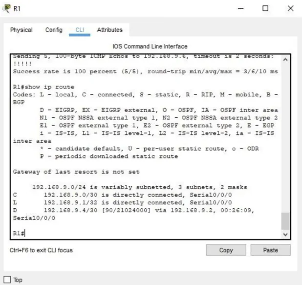
23
Ilustración 2. Evidencia 1
Parte 2: Verificar conectividad de red y control de la trayectoria.
a. Registrar las tablas de enrutamiento en cada uno de los routers, acorde con los parámetros de configuración establecidos en el escenario propuesto.
24
Ilustración 3. Evidencia 2
25 Fuente: Autoría propia
26 Ilustración 5. Evidencia 4
27
Ilustración 6. Evidencia 5
28 Ilustración 7. Evidencia 6
Fuente: Autoría propia
29 Ilustración 8. Evidencia 7
Fuente: Autoría propia
30
1.3.
ESCENARIO 2
Una empresa de comunicaciones presenta una estructura Core acorde a la topología de red, en donde el estudiante será el administrador de la red, el cual deberá configurar e interconectar entre sí cada uno de los dispositivos que forman parte del escenario, acorde con los lineamientos establecidos para el direccionamiento IP, etherchannels, VLANs y demás aspectos que forman parte del escenario propuesto.
Ilustración 3. Topología de red
Parte 1: Configurar la red de acuerdo con las especificaciones.
a. Apagar todas las interfaces en cada switch.
En DLS1.
Switch>enable
Switch#configure terminal
Enter configuration commands, one per line. End with CNTL/Z. Switch(config)#interface range fa0/1-24
31
%LINK-5-CHANGED: Interface FastEthernet0/1, changed state to administratively down
%LINK-5-CHANGED: Interface FastEthernet0/2, changed state to administratively down
%LINK-5-CHANGED: Interface FastEthernet0/3, changed state to administratively down
%LINK-5-CHANGED: Interface FastEthernet0/4, changed state to administratively down
%LINK-5-CHANGED: Interface FastEthernet0/5, changed state to administratively down
%LINK-5-CHANGED: Interface FastEthernet0/13, changed state to administratively down
%LINK-5-CHANGED: Interface FastEthernet0/14, changed state to administratively down
%LINK-5-CHANGED: Interface FastEthernet0/15, changed state to administratively down
%LINK-5-CHANGED: Interface FastEthernet0/16, changed state to administratively down
%LINK-5-CHANGED: Interface FastEthernet0/17, changed state to administratively down
%LINK-5-CHANGED: Interface FastEthernet0/18, changed state to administratively down
%LINK-5-CHANGED: Interface FastEthernet0/19, changed state to administratively down
%LINK-5-CHANGED: Interface FastEthernet0/20, changed state to administratively down
%LINK-5-CHANGED: Interface FastEthernet0/21, changed state to administratively down
%LINK-5-CHANGED: Interface FastEthernet0/22, changed state to administratively down
%LINK-5-CHANGED: Interface FastEthernet0/23, changed state to administratively down
%LINK-5-CHANGED: Interface FastEthernet0/24, changed state to administratively down Switch(config-if-range)#
%LINK-5-CHANGED: Interface FastEthernet0/6, changed state to administratively down
%LINEPROTO-5-UPDOWN: Line protocol on Interface FastEthernet0/6, changed state to down
%LINK-5-CHANGED: Interface FastEthernet0/7, changed state to administratively down
32
%LINK-5-CHANGED: Interface FastEthernet0/8, changed state to administratively down
%LINEPROTO-5-UPDOWN: Line protocol on Interface FastEthernet0/8, changed state to down
%LINK-5-CHANGED: Interface FastEthernet0/9, changed state to administratively down
%LINEPROTO-5-UPDOWN: Line protocol on Interface FastEthernet0/9, changed state to down
%LINK-5-CHANGED: Interface FastEthernet0/10, changed state to administratively down
%LINEPROTO-5-UPDOWN: Line protocol on Interface FastEthernet0/10, changed state to down
%LINK-5-CHANGED: Interface FastEthernet0/11, changed state to administratively down
%LINEPROTO-5-UPDOWN: Line protocol on Interface FastEthernet0/11, changed state to down
%LINK-5-CHANGED: Interface FastEthernet0/12, changed state to administratively down
%LINEPROTO-5-UPDOWN: Line protocol on Interface FastEthernet0/12, changed state to down
Switch(config-if-range)#exit Switch(config)#
En DLS2
Switch>enable
Switch#configure terminal
Enter configuration commands, one per line. End with CNTL/Z. Switch(config)#interface range fa0/1-24
Switch(config-if-range)#shutdown
%LINK-5-CHANGED: Interface FastEthernet0/1, changed state to administratively down
%LINK-5-CHANGED: Interface FastEthernet0/2, changed state to administratively down
33
%LINK-5-CHANGED: Interface FastEthernet0/4, changed state to administratively down
%LINK-5-CHANGED: Interface FastEthernet0/5, changed state to administratively down
%LINK-5-CHANGED: Interface FastEthernet0/11, changed state to administratively down
%LINK-5-CHANGED: Interface FastEthernet0/12, changed state to administratively down
%LINK-5-CHANGED: Interface FastEthernet0/13, changed state to administratively down
%LINK-5-CHANGED: Interface FastEthernet0/14, changed state to administratively down
%LINK-5-CHANGED: Interface FastEthernet0/15, changed state to administratively down
%LINK-5-CHANGED: Interface FastEthernet0/16, changed state to administratively down
%LINK-5-CHANGED: Interface FastEthernet0/17, changed state to administratively down
%LINK-5-CHANGED: Interface FastEthernet0/18, changed state to administratively down
%LINK-5-CHANGED: Interface FastEthernet0/19, changed state to administratively down
%LINK-5-CHANGED: Interface FastEthernet0/20, changed state to administratively down
%LINK-5-CHANGED: Interface FastEthernet0/21, changed state to administratively down
%LINK-5-CHANGED: Interface FastEthernet0/22, changed state to administratively down
%LINK-5-CHANGED: Interface FastEthernet0/23, changed state to administratively down
%LINK-5-CHANGED: Interface FastEthernet0/24, changed state to administratively down Switch(config-if-range)#
%LINK-5-CHANGED: Interface FastEthernet0/6, changed state to administratively down
%LINEPROTO-5-UPDOWN: Line protocol on Interface FastEthernet0/6, changed state to down
%LINK-5-CHANGED: Interface FastEthernet0/7, changed state to administratively down
%LINEPROTO-5-UPDOWN: Line protocol on Interface FastEthernet0/7, changed state to down
34
%LINEPROTO-5-UPDOWN: Line protocol on Interface FastEthernet0/8, changed state to down
%LINK-5-CHANGED: Interface FastEthernet0/9, changed state to administratively down
%LINEPROTO-5-UPDOWN: Line protocol on Interface FastEthernet0/9, changed state to down
%LINK-5-CHANGED: Interface FastEthernet0/10, changed state to administratively down
%LINEPROTO-5-UPDOWN: Line protocol on Interface FastEthernet0/10, changed state to down
Switch(config-if-range)#exit Switch(config)#
En ALS1
Switch>enable
Switch#configure terminal
Enter configuration commands, one per line. End with CNTL/Z. Switch(config)#interface range fa0/1-24
Switch(config-if-range)#shutdown
%LINK-5-CHANGED: Interface FastEthernet0/1, changed state to administratively down
%LINK-5-CHANGED: Interface FastEthernet0/2, changed state to administratively down
%LINK-5-CHANGED: Interface FastEthernet0/3, changed state to administratively down
%LINK-5-CHANGED: Interface FastEthernet0/4, changed state to administratively down
%LINK-5-CHANGED: Interface FastEthernet0/5, changed state to administratively down
%LINK-5-CHANGED: Interface FastEthernet0/7, changed state to administratively down
%LINK-5-CHANGED: Interface FastEthernet0/8, changed state to administratively down
%LINK-5-CHANGED: Interface FastEthernet0/9, changed state to administratively down
35
%LINK-5-CHANGED: Interface FastEthernet0/11, changed state to administratively down
%LINK-5-CHANGED: Interface FastEthernet0/12, changed state to administratively down
%LINK-5-CHANGED: Interface FastEthernet0/13, changed state to administratively down
%LINK-5-CHANGED: Interface FastEthernet0/14, changed state to administratively down
%LINK-5-CHANGED: Interface FastEthernet0/15, changed state to administratively down
%LINK-5-CHANGED: Interface FastEthernet0/16, changed state to administratively down
%LINK-5-CHANGED: Interface FastEthernet0/17, changed state to administratively down
%LINK-5-CHANGED: Interface FastEthernet0/18, changed state to administratively down
%LINK-5-CHANGED: Interface FastEthernet0/19, changed state to administratively down
%LINK-5-CHANGED: Interface FastEthernet0/20, changed state to administratively down
%LINK-5-CHANGED: Interface FastEthernet0/21, changed state to administratively down
%LINK-5-CHANGED: Interface FastEthernet0/22, changed state to administratively down
%LINK-5-CHANGED: Interface FastEthernet0/23, changed state to administratively down
%LINK-5-CHANGED: Interface FastEthernet0/24, changed state to administratively down Switch(config-if-range)#
%LINK-5-CHANGED: Interface FastEthernet0/6, changed state to administratively down
%LINEPROTO-5-UPDOWN: Line protocol on Interface FastEthernet0/6, changed state to down
36 En ALS2
Switch>enable
Switch#configure terminal
Enter configuration commands, one per line. End with CNTL/Z. Switch(config)#interface range fa0/1-24
Switch(config-if-range)#shutdown
%LINK-5-CHANGED: Interface FastEthernet0/1, changed state to administratively down
%LINK-5-CHANGED: Interface FastEthernet0/2, changed state to administratively down
%LINK-5-CHANGED: Interface FastEthernet0/3, changed state to administratively down
%LINK-5-CHANGED: Interface FastEthernet0/4, changed state to administratively down
%LINK-5-CHANGED: Interface FastEthernet0/5, changed state to administratively down
%LINK-5-CHANGED: Interface FastEthernet0/7, changed state to administratively down
%LINK-5-CHANGED: Interface FastEthernet0/8, changed state to administratively down
%LINK-5-CHANGED: Interface FastEthernet0/9, changed state to administratively down
%LINK-5-CHANGED: Interface FastEthernet0/10, changed state to administratively down
%LINK-5-CHANGED: Interface FastEthernet0/11, changed state to administratively down
%LINK-5-CHANGED: Interface FastEthernet0/12, changed state to administratively down
%LINK-5-CHANGED: Interface FastEthernet0/13, changed state to administratively down
%LINK-5-CHANGED: Interface FastEthernet0/14, changed state to administratively down
%LINK-5-CHANGED: Interface FastEthernet0/15, changed state to administratively down
%LINK-5-CHANGED: Interface FastEthernet0/16, changed state to administratively down
%LINK-5-CHANGED: Interface FastEthernet0/17, changed state to administratively down
%LINK-5-CHANGED: Interface FastEthernet0/18, changed state to administratively down
37
%LINK-5-CHANGED: Interface FastEthernet0/20, changed state to administratively down
%LINK-5-CHANGED: Interface FastEthernet0/21, changed state to administratively down
%LINK-5-CHANGED: Interface FastEthernet0/22, changed state to administratively down
%LINK-5-CHANGED: Interface FastEthernet0/23, changed state to administratively down
%LINK-5-CHANGED: Interface FastEthernet0/24, changed state to administratively down Switch(config-if-range)#
%LINK-5-CHANGED: Interface FastEthernet0/6, changed state to administratively down
%LINEPROTO-5-UPDOWN: Line protocol on Interface FastEthernet0/6, changed state to down
Switch(config-if-range)#exit Switch(config)#
b. Asignar un nombre a cada switch acorde al escenario establecido.
En DLS1.
Switch#configure terminal
Enter configuration commands, one per line. End with CNTL/Z. Switch(config)#hostname DLS1
DLS1(config)#
En DLS2
Switch#configure terminal
Enter configuration commands, one per line. End with CNTL/Z. Switch(config)#hostname DLS2
38 En ALS1
Switch#configure terminal
Enter configuration commands, one per line. End with CNTL/Z. Switch(config)#hostname ALS1
ALS1(config)#
En ALS2
Switch#configure terminal
Enter configuration commands, one per line. End with CNTL/Z. Switch(config)#hostname ALS2
ALS2(config)#
c. Configurar los puertos troncales y Port-channels tal como se muestra en el diagrama.
1) La conexión entre DLS1 y DLS2 será un EtherChannel capa-3 utilizando LACP. Para DLS1 se utilizará la dirección IP 10.12.12.1/30 y para DLS2 utilizará
10.12.12.2/30.
En DLS1.
DLS1#configure terminal
Enter configuration commands, one per line. End with CNTL/Z. DLS1(config)#interface fastethernet0/11
DLS1(config-if)#channel-group 1 mode active DLS1(config-if)#no shutdown
%LINK-5-CHANGED: Interface FastEthernet0/11, changed state to down DLS1(config-if)#description "Conexion Sw DLS2 Port Fa0/11"
39 DLS1(config)#interface fastethernet0/12
DLS1(config-if)#channel-group 1 mode active DLS1(config-if)#no shutdown
%LINK-5-CHANGED: Interface FastEthernet0/12, changed state to down DLS1(config-if)#description "Conexion Sw DLS2 Port Fa0/12"
DLS1(config-if)#exit
Creating a port-channel interface Port-channel 1 DLS1(config)#interface port-channel 1
DLS1(config-if)#no switchport
DLS1(config-if)#ip address 10.12.12.1 255.255.255.252
DLS1(config-if)#description "Channel Group 1 Ports 11-12" DLS1(config-if)#no shutdown
DLS1(config-if)#exit
En DLS2.
DLS2#configure terminal
Enter configuration commands, one per line. End with CNTL/Z. DLS2(config)#interface fastethernet0/11
DLS2(config-if)#channel-group 1 mode active DLS2(config-if)#no shutdown
DLS2(config-if)#description "Conexion Sw DLS1 Port Fa0/11" DLS2(config-if)#exit
DLS2(config)#interface fastethernet0/12
DLS2(config-if)#channel-group 1 mode active DLS2(config-if)#no shutdown
DLS2(config-if)#description "Conexion Sw DLS1 Port Fa0/12" DLS2(config-if)#exit
DLS2(config)#interface port-channel 1 DLS2(config-if)#no switchport
DLS2(config-if)#ip address 10.12.12.2 255.255.255.252
DLS2(config-if)#description "Channel Group 1 Ports 11-12" DLS2(config-if)#no shutdown
DLS2(config-if)#exit
Creating a port-channel interface Port-channel 1
40
%LINEPROTO-5-UPDOWN: Line protocol on Interface FastEthernet0/11, changed state to up
%LINK-5-CHANGED: Interface FastEthernet0/12, changed state to up
%LINEPROTO-5-UPDOWN: Line protocol on Interface FastEthernet0/12, changed state to up
%LINK-5-CHANGED: Interface Port-channel1, changed state to up
%LINEPROTO-5-UPDOWN: Line protocol on Interface Port-channel1, changed state to up
2) Los Port-channels en las interfaces Fa0/7 y Fa0/8 utilizarán LACP.
En DLS1.
DLS1#configure terminal
Enter configuration commands, one per line. End with CNTL/Z. DLS1(config)#interface fastethernet0/7
DLS1(config-if)#channel-group 2 mode active DLS1(config-if)#no shutdown
%LINK-5-CHANGED: Interface FastEthernet0/7, changed state to down DLS1(config-if)#description "Conexion Sw ALS1 Port Fe0/7"
DLS1(config-if)#exit
DLS1(config)#interface fastethernet0/8
DLS1(config-if)#channel-group 2 mode active DLS1(config-if)#no shutdown
%LINK-5-CHANGED: Interface FastEthernet0/8, changed state to down DLS1(config-if)#description "Conexion Sw ALS1 Port Fe0/8"
DLS1(config-if)#exit
Creating a port-channel interface Port-channel 2
41 En DLS2
DLS2#configure terminal
Enter configuration commands, one per line. End with CNTL/Z. DLS2(config)#interface fastethernet0/7
DLS2(config-if)#channel-group 2 mode active DLS2(config-if)#no shutdown
%LINK-5-CHANGED: Interface FastEthernet0/7, changed state to down DLS2(config-if)#description "Conexion Sw ALS2 Port Fe0/7"
DLS2(config-if)#exit
DLS2(config)#interface fastethernet0/8
DLS2(config-if)#channel-group 2 mode active DLS2(config-if)#no shutdown
%LINK-5-CHANGED: Interface FastEthernet0/8, changed state to down DLS2(config-if)#description "Conexion Sw ALS2 Port Fe0/8"
DLS2(config-if)#exit
Creating a port-channel interface Port-channel 2
DLS2(config)#
En ALS1
ALS1#configure terminal
Enter configuration commands, one per line. End with CNTL/Z. ALS1(config)#interface fastethernet0/7
ALS1(config-if)#channel-group 2 mode active ALS1(config-if)#no shutdown
ALS1(config-if)#description "Conexion Sw DLS1 Port Fe0/7" ALS1(config-if)#exit
ALS1(config)#interface fastethernet0/8
ALS1(config-if)#channel-group 2 mode active ALS1(config-if)#no shutdown
ALS1(config-if)#description "Conexion Sw DLS1 Port Fe0/8" ALS1(config-if)#exit
42
%LINK-5-CHANGED: Interface FastEthernet0/7, changed state to up
%LINEPROTO-5-UPDOWN: Line protocol on Interface FastEthernet0/7, changed state to up
%LINK-5-CHANGED: Interface FastEthernet0/8, changed state to up
%LINEPROTO-5-UPDOWN: Line protocol on Interface FastEthernet0/8, changed state to up
%LINK-5-CHANGED: Interface Port-channel2, changed state to up
%LINEPROTO-5-UPDOWN: Line protocol on Interface Port-channel2, changed state to up
ALS1(config)#
En ALS2
ALS2#configure terminal
Enter configuration commands, one per line. End with CNTL/Z. ALS2(config)#interface fastethernet0/7
ALS2(config-if)#channel-group 2 mode active ALS2(config-if)#no shutdown
ALS2(config-if)#description "Conexion Sw DLS2 Port Fe0/7" ALS2(config-if)#exit
ALS2(config)#interface fastethernet0/8
ALS2(config-if)#channel-group 2 mode active ALS2(config-if)#no shutdown
ALS2(config-if)#description "Conexion Sw DLS2 Port Fe0/8" ALS2(config-if)#exit
Creating a port-channel interface Port-channel 2
%LINK-5-CHANGED: Interface FastEthernet0/7, changed state to up
43
%LINK-5-CHANGED: Interface FastEthernet0/8, changed state to up
%LINEPROTO-5-UPDOWN: Line protocol on Interface FastEthernet0/8, changed state to up
%LINK-5-CHANGED: Interface Port-channel2, changed state to up
%LINEPROTO-5-UPDOWN: Line protocol on Interface Port-channel2, changed state to up
ALS2(config)#
3) Los Port-channels en las interfaces F0/9 y fa0/10 utilizará PAgP.
En DLS1.
DLS1#configure terminal
Enter configuration commands, one per line. End with CNTL/Z. DLS1(config)#interface fastethernet0/9
DLS1(config-if)#channel-group 3 mode desirable DLS1(config-if)#no shutdown
%LINK-5-CHANGED: Interface FastEthernet0/9, changed state to down DLS1(config-if)#description "Conexion Sw ALS2 Port Fe0/9"
DLS1(config-if)#exit
DLS1(config)#interface fastethernet0/10
DLS1(config-if)#channel-group 3 mode desirable DLS1(config-if)#no shutdown
%LINK-5-CHANGED: Interface FastEthernet0/10, changed state to down DLS1(config-if)#description "Conexion Sw ALS2 Port Fe0/10"
DLS1(config-if)#exit
Creating a port-channel interface Port-channel 3
44 En DLS2
DLS2#configure terminal
Enter configuration commands, one per line. End with CNTL/Z. DLS2(config)#interface fastethernet0/9
DLS2(config-if)#channel-group 3 mode desirable DLS2(config-if)#no shutdown
%LINK-5-CHANGED: Interface FastEthernet0/9, changed state to down DLS2(config-if)#description "Conexion Sw ALS1 Port Fe0/9"
DLS2(config-if)#exit
DLS2(config)#interface fastethernet0/10
DLS2(config-if)#channel-group 3 mode desirable DLS2(config-if)#no shutdown
%LINK-5-CHANGED: Interface FastEthernet0/10, changed state to down DLS2(config-if)#description "Conexion Sw ALS1 Port Fe0/10"
DLS2(config-if)#exit
Creating a port-channel interface Port-channel 3
DLS2(config)#
En ALS1
ALS1#configure terminal
Enter configuration commands, one per line. End with CNTL/Z. ALS1(config)#interface fastethernet0/9
ALS1(config-if)#channel-group 3 mode desirable ALS1(config-if)#no shutdown
ALS1(config-if)#description "Conexion Sw DLS2 Port Fe0/9" ALS1(config-if)#exit
ALS1(config)#interface fastethernet0/10
ALS1(config-if)#channel-group 3 mode desirable ALS1(config-if)#no shutdown
ALS1(config-if)#description "Conexion Sw DLS2 Port Fe0/10" ALS1(config-if)#exit
45
%LINK-5-CHANGED: Interface FastEthernet0/9, changed state to up
%LINEPROTO-5-UPDOWN: Line protocol on Interface FastEthernet0/9, changed state to up
%LINK-5-CHANGED: Interface FastEthernet0/10, changed state to up
%LINEPROTO-5-UPDOWN: Line protocol on Interface FastEthernet0/10, changed state to up
%LINK-5-CHANGED: Interface Port-channel3, changed state to up
%LINEPROTO-5-UPDOWN: Line protocol on Interface Port-channel3, changed state to up
ALS1(config)#
En ALS2
ALS2#configure terminal
Enter configuration commands, one per line. End with CNTL/Z. ALS2(config)#interface fastethernet0/9
ALS2(config-if)#channel-group 3 mode desirable ALS2(config-if)#no shutdown
ALS2(config-if)#description "Conexion Sw DLS1 Port Fe0/9" ALS2(config-if)#exit
ALS2(config)#interface fastethernet0/10
ALS2(config-if)#channel-group 3 mode desirable ALS2(config-if)#no shutdown
ALS2(config-if)#description "Conexion Sw DLS1 Port Fe0/10" ALS2(config-if)#exit
Creating a port-channel interface Port-channel 3
%LINK-5-CHANGED: Interface FastEthernet0/9, changed state to up
46
%LINK-5-CHANGED: Interface FastEthernet0/10, changed state to up
%LINEPROTO-5-UPDOWN: Line protocol on Interface FastEthernet0/10, changed state to up
%LINK-5-CHANGED: Interface Port-channel3, changed state to up
%LINEPROTO-5-UPDOWN: Line protocol on Interface Port-channel3, changed state to up
ALS2(config)#
4) Todos los puertos troncales serán asignados a la VLAN 800 como la VLAN
nativa.
En DLS1.
DLS1#configure terminal
Enter configuration commands, one per line. End with CNTL/Z. DLS1(config)#vlan 800
DLS1(config-vlan)#name NATIVA DLS1(config-vlan)#exit
DLS1(config)#interface range fastethernet0/7-12
DLS1(config-if-range)#switchport trunk native vlan 800 DLS1(config-if-range)#exit
DLS1(config)#
En DLS2.
DLS2(config)#vlan 800
DLS2(config-vlan)#name NATIVA DLS2(config-vlan)#exit
DLS2(config)#interface range fastethernet0/7-12
DLS2(config-if-range)#switchport trunk native vlan 800 DLS2(config-if-range)#exit
47 DLS2#
En ALS1.
ALS1#configure terminal
Enter configuration commands, one per line. End with CNTL/Z. ALS1(config)#vlan 800
ALS1(config-vlan)#name NATIVA ALS1(config-vlan)#exit
ALS1(config)#interface range fastethernet0/7-12
ALS1(config-if-range)#switchport trunk native vlan 800 ALS1(config-if-range)#exit
ALS1(config)#
En ALS2.
ALS2#configure terminal
Enter configuration commands, one per line. End with CNTL/Z. ALS2(config)#vlan 800
ALS2(config-vlan)#name NATIVA ALS2(config-vlan)#exit
ALS2(config)#interface range fastethernet0/7-12
ALS2(config-if-range)#switchport trunk native vlan 800 ALS2(config-if-range)#exit
ALS2(config)#
a. Configurar DLS1, ALS1, y ALS2 para utilizar VTP versión 3
En DLS1.
DLS1#configure terminal
48 DLS1(config)#vtp version 2
En ALS1.
ALS1#configure terminal
Enter configuration commands, one per line. End with CNTL/Z. ALS1(config)#vtp version 2
En ALS2.
ALS2#configure terminal
Enter configuration commands, one per line. End with CNTL/Z. ALS2(config)#vtp version 2
ALS2(config)#
1) Utilizar el nombre de dominio UNAD con la contraseña cisco123
En DLS1.
DLS1(config)#vtp domain UNAD
Changing VTP domain name from NULL to UNAD DLS1(config)#vtp password cisco123
Setting device VLAN database password to cisco123 DLS1(config)#
En ALS1.
ALS1(config)#vtp domain UNAD
49 ALS1(config)#vtp password cisco123
Setting device VLAN database password to cisco123 ALS1(config)#
En ALS2.
ALS2(config)#vtp domain UNAD
Changing VTP domain name from NULL to UNAD ALS2(config)#vtp password cisco123
Setting device VLAN database password to cisco123 ALS2(config)#
2) Configurar DLS1 como servidor principal para las VLAN.
En DLS1.
DLS1(config)#vtp domain server
Changing VTP domain name from UNAD to server
DLS1(config)#00:32:11 %DTP-5-DOMAINMISMATCH: Unable to perform trunk negotiation on port Po3 because of VTP domain mismatch.
DLS1(config)#
3) Configurar ALS1 y ALS2 como clientes VTP.
En ALS1.
ALS1(config)#vtp mode client
50 En ALS2.
ALS2(config)#vtp mode client
Setting device to VTP CLIENT mode. ALS2(config)#
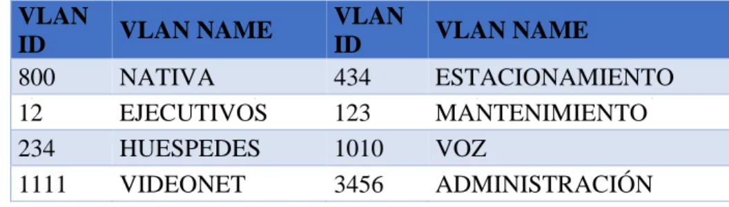
a. Configurar en el servidor principal las siguientes VLAN: En DLS1.
Tabla 1. Configuraciones en DLS1
VLAN
ID VLAN NAME
VLAN
ID VLAN NAME
800 NATIVA 434 ESTACIONAMIENTO
12 EJECUTIVOS 123 MANTENIMIENTO
234 HUESPEDES 1010 VOZ
1111 VIDEONET 3456 ADMINISTRACIÓN
DLS1#configure terminal
Enter configuration commands, one per line. End with CNTL/Z. DLS1(config)#vlan 12
DLS1(config-vlan)#name EJECUTIVOS DLS1(config-vlan)#vlan 234
DLS1(config-vlan)#name HUESPEDES DLS1(config-vlan)#vlan 1111
VLAN_CREATE_FAIL: Failed to create VLANs 1111 : extended VLAN(s) not allowed in current VTP mode
DLS1(config)#name VIDEONET ^
% Invalid input detected at '^' marker. DLS1(config)#vlan 434
DLS1(config-vlan)#name ESTACIONAMIENTO DLS1(config-vlan)#vlan 123
51 DLS1(config)#name VOZ
^
% Invalid input detected at '^' marker. DLS1(config)#vlan 3456
VLAN_CREATE_FAIL: Failed to create VLANs 3456 : extended VLAN(s) not allowed in current VTP mode
DLS1(config)#name ADMINISTRACION ^
% Invalid input detected at '^' marker.
b. En DLS1, suspender la VLAN 434.
En DLS1.
DLS1#configure terminal DLS1(config)#vlan 434
DLS1(config-vlan)#state suspend ^
% Invalid input detected at '^' marker. DLS1(config-vlan)#exit
DLS1(config)#
c. Configurar DLS2 en modo VTP transparente VTP utilizando VTP versión 2, y configurar en DLS2 las mismas VLAN que en DLS1.
En DLS2.
DLS2#configure terminal
Enter configuration commands, one per line. End with CNTL/Z. DLS2(config)#vtp version 2
DLS2(config)#vtp mode transparent
52 DLS2(config)#vlan 12
DLS2(config-vlan)#name EJECUTIVOS DLS2(config-vlan)#vlan 234
DLS2(config-vlan)#name HUESPEDES DLS2(config-vlan)#vlan 1111
DLS2(config-vlan)#name VIDEONET DLS2(config-vlan)#vlan 123
DLS2(config-vlan)#name MANTENIMIENTO DLS2(config-vlan)#vlan 1010
DLS2(config-vlan)#name VOZ DLS2(config-vlan)#vlan 3456
DLS2(config-vlan)#name ADMINISTRACION DLS2(config-vlan)#vlan 434
DLS2(config-vlan)#name ESTACIONAMIENTO DLS2(config-vlan)#exit
DLS2(config)#
d. Suspender VLAN 434 en DLS2.
En DLS2.
DLS2(config)#
DLS2(config)#vlan 434
DLS2(config-vlan)#state suspend ^
% Invalid input detected at '^' marker. DLS2(config-vlan)#exit
DLS2(config)#
e. En DLS2, crear VLAN 567 con el nombre de CONTABILIDAD. La VLAN de
CONTABILIDAD no podrá estar disponible en cualquier otro Switch de la red.
53 DLS2(config)#
DLS2(config)#vlan 567
DLS2(config-vlan)#name CONTABILIDAD DLS2(config-vlan)#exit
DLS2(config)#
f. Configurar DLS1 como Spanning tree root para las VLAN 1, 12, 434, 800, 1010, 1111 y 3456 y como raíz secundaria para las VLAN 123 y 234.
En DLS1.
DLS1#
DLS1#configure terminal
Enter configuration commands, one per line. End with CNTL/Z. DLS1(config)#
DLS1(config)#spanning-tree vlan 1 root primary DLS1(config)#spanning-tree vlan 12 root primary DLS1(config)#spanning-tree vlan 434 root primary DLS1(config)#spanning-tree vlan 800 root primary DLS1(config)#spanning-tree vlan 1010 root primary DLS1(config)#spanning-tree vlan 1111 root primary DLS1(config)#spanning-tree vlan 3456 root primary DLS1(config)#spanning-tree vlan 123 root secondary DLS1(config)#spanning-tree vlan 234 root secondary DLS1(config)#
g. Configurar DLS2 como Spanning tree root para las VLAN 123 y 234 y como una raíz secundaria para las VLAN 12, 434, 800, 1010, 1111 y 3456.
En DLS2.
DLS2(config)#
54
DLS2(config)#spanning-tree vlan 12 root secondary DLS2(config)#spanning-tree vlan 434 root secondary DLS2(config)#spanning-tree vlan 800 root secondary DLS2(config)#spanning-tree vlan 1010 root secondary DLS2(config)#spanning-tree vlan 1111 root secondary DLS2(config)#spanning-tree vlan 3456 root secondary DLS2(config)#
h. Configurar todos los puertos como troncales de tal forma que solamente las VLAN que se han creado se les permitirá circular a través de éstos puertos.
En DLS2.
DLS2(config)#
DLS2(config)#interface range fas
DLS2(config)#interface range fastEthernet 0/1-24 DLS2(config-if-range)#switchport mode trunk
Command rejected: An interface whose trunk encapsulation is "Auto" can not be configured to "trunk" mode.
Command rejected: An interface whose trunk encapsulation is "Auto" can not be configured to "trunk" mode.
Command rejected: An interface whose trunk encapsulation is "Auto" can not be configured to "trunk" mode.
Command rejected: An interface whose trunk encapsulation is "Auto" can not be configured to "trunk" mode.
Command rejected: An interface whose trunk encapsulation is "Auto" can not be configured to "trunk" mode.
Command rejected: An interface whose trunk encapsulation is "Auto" can not be configured to "trunk" mode.
Command rejected: An interface whose trunk encapsulation is "Auto" can not be configured to "trunk" mode.
Command rejected: An interface whose trunk encapsulation is "Auto" can not be configured to "trunk" mode.
Command rejected: An interface whose trunk encapsulation is "Auto" can not be configured to "trunk" mode.
55
Command rejected: An interface whose trunk encapsulation is "Auto" can not be configured to "trunk" mode.
Command rejected: An interface whose trunk encapsulation is "Auto" can not be configured to "trunk" mode.
Command rejected: An interface whose trunk encapsulation is "Auto" can not be configured to "trunk" mode.
Command rejected: An interface whose trunk encapsulation is "Auto" can not be configured to "trunk" mode.
Command rejected: An interface whose trunk encapsulation is "Auto" can not be configured to "trunk" mode.
Command rejected: An interface whose trunk encapsulation is "Auto" can not be configured to "trunk" mode.
Command rejected: An interface whose trunk encapsulation is "Auto" can not be configured to "trunk" mode.
Command rejected: An interface whose trunk encapsulation is "Auto" can not be configured to "trunk" mode.
Command rejected: An interface whose trunk encapsulation is "Auto" can not be configured to "trunk" mode.
Command rejected: An interface whose trunk encapsulation is "Auto" can not be configured to "trunk" mode.
Command rejected: An interface whose trunk encapsulation is "Auto" can not be configured to "trunk" mode.
Command rejected: An interface whose trunk encapsulation is "Auto" can not be configured to "trunk" mode.
Command rejected: An interface whose trunk encapsulation is "Auto" can not be configured to "trunk" mode.
Command rejected: An interface whose trunk encapsulation is "Auto" can not be configured to "trunk" mode.
DLS2(config-if-range)#exit DLS2(config)#
i. Configurar las siguientes interfaces como puertos de acceso, asignados a las VLAN de la siguiente manera:
Tabla 2. Configuraciones para interfaces
Interfaz DLS1 DLS2 ALS1 ALS2
Interfaz Fa0/6 3456 12,1010 123,1010 234
Interfaz Fa0/15 1111 1111
1111
56 En DLS1.
DLS1(config)#
DLS1(config)#interface fastethernet0/6 DLS1(config-if)#switchport mode access DLS1(config-if)#switchport access vlan 3456
% Access VLAN does not exist. Creating vlan 3456 DLS1(config-if)#no shutdown
DLS1(config-if)#interface fastethernet0/15 DLS1(config-if)#switchport mode access DLS1(config-if)#switchport access vlan 1111
% Access VLAN does not exist. Creating vlan 1111 DLS1(config-if)#no shutdown
%LINK-5-CHANGED: Interface FastEthernet0/15, changed state to down DLS1(config-if)#exit
%LINK-5-CHANGED: Interface FastEthernet0/6, changed state to up
En DLS2.
DLS2#configure terminal
Enter configuration commands, one per line. End with CNTL/Z. DLS2(config)#
DLS2(config)#interface fastethernet0/6 DLS2(config-if)#switchport mode access DLS2(config-if)#switchport access vlan 12 DLS2(config-if)#no shutdown
57
%LINK-5-CHANGED: Interface FastEthernet0/15, changed state to down DLS2(config-if)#interface range fastethernet0/16-18
DLS2(config-if-range)#switchport mode access DLS2(config-if-range)#switchport access vlan 567 DLS2(config-if-range)#no shutdown
%LINK-5-CHANGED: Interface FastEthernet0/16, changed state to down
%LINK-5-CHANGED: Interface FastEthernet0/17, changed state to down
%LINK-5-CHANGED: Interface FastEthernet0/18, changed state to down DLS2(config-if-range)#exit
%LINK-5-CHANGED: Interface FastEthernet0/6, changed state to up
%LINEPROTO-5-UPDOWN: Line protocol on Interface FastEthernet0/6, changed state to up
En ALS1.
ALS1#configure terminal
Enter configuration commands, one per line. End with CNTL/Z. ALS1(config)#interface fastethernet0/6
ALS1(config-if)#switchport mode access ALS1(config-if)#switchport access vlan 123 ALS1(config-if)#no shutdown
ALS1(config-if)#interface fastethernet0/15 ALS1(config-if)#switchport mode access ALS1(config-if)#switchport access vlan 1111 ALS1(config-if)#no shutdown
%LINK-5-CHANGED: Interface FastEthernet0/15, changed state to down ALS1(config-if)#exit
%LINK-5-CHANGED: Interface FastEthernet0/6, changed state to up
%LINEPROTO-5-UPDOWN: Line protocol on Interface FastEthernet0/6, changed state to up
58 En ALS2.
ALS2#configure terminal
Enter configuration commands, one per line. End with CNTL/Z. ALS2(config)#interface fastethernet0/6
ALS2(config-if)#switchport mode access ALS2(config-if)#switchport access vlan 234 ALS2(config-if)#no shutdown
ALS2(config-if)#interface fastethernet0/15 ALS2(config-if)#switchport mode access ALS2(config-if)#switchport access vlan 1111 ALS2(config-if)#no shutdown
%LINK-5-CHANGED: Interface FastEthernet0/15, changed state to down ALS2(config-if)#exit
%LINK-5-CHANGED: Interface FastEthernet0/6, changed state to up
%LINEPROTO-5-UPDOWN: Line protocol on Interface FastEthernet0/6, changed state to up
ALS2(config)#
Parte 2: conectividad de red de prueba y las opciones configuradas.
a. Verificar la existencia de las VLAN correctas en todos los switches y la asignación de puertos troncales y de acceso
b. Verificar que el EtherChannel entre DLS1 y ALS1 está configurado correctamente
59
CONCLUSIONES
De acuerdo con lo indicado en la práctica se pudo observar y aprender cómo se configura una red a través de switching basado en protocolos avanzados de capa 2 pasando por capa 3 otorgando conectividad entre los hosts de la red.
Así mismo con el desarrollo de la actividad se pudieron adquirir las habilidades de gestión de redes orientadas hacia el mundo profesional y corporativo, además necesarios para planificar, implementar, asegurar, mantener y solucionar problemas de redes convergentes.
La administración de aplicación o de proyectos más simples nos permite que las VLAN agregan dispositivos de red y usuarios para admitir los requerimientos geográficos o comerciales.
60
REFERENCIAS BIBLIOGRÁFICAS.
Donohue, D. (2017). CISCO Press (Ed). CCNP Quick Reference. Recuperado de
https://1drv.ms/b/s!AgIGg5JUgUBthFt77ehzL5qp0OKD
Froom, R., Frahim, E. (2015). CISCO Press (Ed). Campus Network Architecture. Implementing Cisco IP Switched Networks (SWITCH) Foundation Learning Guide CCNP SWITCH 300-115. Recuperado de https://1drv.ms/b/s!AmIJYei-NT1IlnWR0hoMxgBNv1CJ
Froom, R., Frahim, E. (2015). CISCO Press (Ed). Campus Network Security. Implementing Cisco IP Switched Networks (SWITCH) Foundation Learning Guide CCNP SWITCH 300-115. Recuperado de https://1drv.ms/b/s!AmIJYei-NT1IlnWR0hoMxgBNv1CJ
Froom, R., Frahim, E. (2015). CISCO Press (Ed). First Hop Redundancy Protocols. Implementing Cisco IP Switched Networks (SWITCH) Foundation Learning Guide CCNP SWITCH 300-115. Recuperado de https://1drv.ms/b/s!AmIJYei-NT1IlnWR0hoMxgBNv1CJ
Froom, R., Frahim, E. (2015). CISCO Press (Ed). High Availability. Implementing Cisco IP Switched Networks (SWITCH) Foundation Learning Guide CCNP SWITCH
300-115. Recuperado de https://1drv.ms/b/s!AmIJYei-NT1IlnWR0hoMxgBNv1CJ
Froom, R., Frahim, E. (2015). CISCO Press (Ed). InterVLAN Routing. Implementing Cisco IP Switched Networks (SWITCH) Foundation Learning Guide CCNP SWITCH
61
Froom, R., Frahim, E. (2015). CISCO Press (Ed). Network Design Fundamentals. Implementing Cisco IP Switched Networks (SWITCH) Foundation Learning Guide CCNP SWITCH 300-115. Recuperado de https://1drv.ms/b/s!AmIJYei-NT1IlnWR0hoMxgBNv1CJ
Froom, R., Frahim, E. (2015). CISCO Press (Ed). Network Management. Implementing Cisco IP Switched Networks (SWITCH) Foundation Learning Guide CCNP SWITCH 300-115. Recuperado de https://1drv.ms/b/s!AmIJYei-NT1IlnWR0hoMxgBNv1CJ
Froom, R., Frahim, E. (2015). CISCO Press (Ed). Spanning Tree Implementation. Implementing Cisco IP Switched Networks (SWITCH) Foundation Learning Guide CCNP SWITCH 300-115. Recuperado de https://1drv.ms/b/s!AmIJYei-NT1IlnWR0hoMxgBNv1CJ
Froom, R., Frahim, E. (2015). CISCO Press (Ed). Switch Fundamentals Review. Implementing Cisco IP Switched Networks (SWITCH) Foundation Learning Guide CCNP SWITCH 300-115. Recuperado de https://1drv.ms/b/s!AmIJYei-NT1IlnWR0hoMxgBNv1CJ
Froom, R., Frahim, E. (2015). CISCO Press (Ed). v. Implementing Cisco IP Switched Networks (SWITCH) Foundation Learning Guide CCNP SWITCH 300-115.
Recuperado de https://1drv.ms/b/s!AmIJYei-NT1IlnWR0hoMxgBNv1CJ
Hucaby, D. (2015). CISCO Press (Ed). CCNP Routing and Switching SWITCH 300-
115 Official Cert Guide. Recuperado de
https://1drv.ms/b/s!AgIGg5JUgUBthF16RWCSsCZnfDo2
Macfarlane, J. (2014). Network Routing Basics : Understanding IP Routing in Cisco
62
http://bibliotecavirtual.unad.edu.co:2048/login?url=http://search.ebscohost.com/logi n.aspx?direct=true&db=e000xww&AN=158227&lang=es&site=ehost-live
Teare, D., Vachon B., Graziani, R. (2015). CISCO Press (Ed). Basic Network and Routing Concepts. Implementing Cisco IP Routing (ROUTE) Foundation Learning Guide CCNP ROUTE 300-101. Recuperado de https://1drv.ms/b/s!AmIJYei-NT1IlnMfy2rhPZHwEoWx
Teare, D., Vachon B., Graziani, R. (2015). CISCO Press (Ed). EIGRP Implementation. Implementing Cisco IP Routing (ROUTE) Foundation Learning Guide CCNP ROUTE 300-101. Recuperado de https://1drv.ms/b/s!AmIJYei-NT1IlnMfy2rhPZHwEoWx
Teare, D., Vachon B., Graziani, R. (2015). CISCO Press (Ed). Enterprise Internet Connectivity. Implementing Cisco IP Routing (ROUTE) Foundation Learning Guide CCNP ROUTE 300-101. Recuperado de https://1drv.ms/b/s!AmIJYei-NT1IlnMfy2rhPZHwEoWx
Teare, D., Vachon B., Graziani, R. (2015). CISCO Press (Ed). Implementing a Border Gateway Protocol (BGP). Implementing Cisco IP Routing (ROUTE)
Foundation Learning Guide CCNP ROUTE 300-101. Recuperado de
https://1drv.ms/b/s!AmIJYei-NT1IlnMfy2rhPZHwEoWx
Teare, D., Vachon B., Graziani, R. (2015). CISCO Press (Ed). Manipulating Routing Updates. Implementing Cisco IP Routing (ROUTE) Foundation Learning Guide CCNP ROUTE 300-101. Recuperado de https://1drv.ms/b/s!AmIJYei-NT1IlnMfy2rhPZHwEoWx
63
Guide CCNP ROUTE 300-101. Recuperado de
https://1drv.ms/b/s!AmIJYei-NT1IlnMfy2rhPZHwEoWx
Teare, D., Vachon B., Graziani, R. (2015). CISCO Press (Ed). Path Control Implementation. Implementing Cisco IP Routing (ROUTE) Foundation Learning Guide CCNP ROUTE 300-101. Recuperado de https://1drv.ms/b/s!AmIJYei-NT1IlnMfy2rhPZHwEoWx
Teare, D., Vachon B., Graziani, R. (2015). CISCO Press (Ed). Routers and Routing Protocol Hardening. Implementing Cisco IP Routing (ROUTE) Foundation Learning Guide CCNP ROUTE 300-101. Recuperado de https://1drv.ms/b/s!AmIJYei-NT1IlnMfy2rhPZHwEoWx
UNAD (2015). Introducción a la configuración de Switches y Routers [OVA].
Recuperado de https://1drv.ms/u/s!AmIJYei-NT1IhgL9QChD1m9EuGqC
UNAD (2015). Principios de Enrutamiento [OVA]. Recuperado de
https://1drv.ms/u/s!AmIJYei-NT1IhgOyjWeh6timi_Tm
UNAD (2015). Switch CISCO - Procedimientos de instalación y configuración del
IOS [OVA]. Recuperado de https://1drv.ms/u/s!AmIJYei-NT1IlyYRohwtwPUV64dg
UNAD (2015). Switch CISCO Security Management [OVA]. Recuperado de
https://1drv.ms/u/s!AmIJYei-NT1IlyVeVJCCezJ2QE5c
Wallace, K. (2015). CISCO Press (Ed). CCNP Routing and Switching ROUTE 300-
101 Official Cert Guide. Recuperado de
64
Wallace, K. (2015). CISCO Press (Ed). CCNP Routing and Switching ROUTE 300-
101 Official Cert Guide. Recuperado de