DIPLOMADO DE PROFUNDIZACION CISCO PRUEBA DE HABILIDADES PRÁCTICAS CCNP
HARRINSON URREA MONTEALEGRE
UNIVERSIDAD NACIONAL ABIERTA Y A DISTANCIA - UNAD
ESCUELA DE CIENCIAS BÁSICAS, TECNOLOGÍA E INGENIERÍA - ECBTI INGENIERÍA EN TELECOMUNICACIONES
DIPLOMADO DE PROFUNDIZACION CISCO PRUEBA DE HABILIDADES PRÁCTICAS CCNP
HARRINSON URREA MONTEALEGRE
Diplomado de opción de grado presentado para optar el título de INGENIERO EN TELECOMUNICACIONES
DIRECTOR:
MSc. GERARDO GRANADOS ACUÑA
UNIVERSIDAD NACIONAL ABIERTA Y A DISTANCIA - UNAD
ESCUELA DE CIENCIAS BÁSICAS, TECNOLOGÍA E INGENIERÍA - ECBTI INGENIERÍA EN TELECOMUNICACIONES
NOTA DE ACEPTACIÓN
Firma del Presidente del Jurado
Firma del Jurado
Firma del Jurado
AGRADECIMIENTOS
A Dios, a mi familia, que me permitieron adquirir nuevos conocimientos, que nos da la oportunidad de mejorar la calidad de vida en el futuro, a corto plazo esperado
A los tutores y directores de cursos en el transcurso de la carrera, compañeros de los grupos colaborativos, que juntos trabajamos para el cumplimento de objetivos, metas y aprendizaje.
CONTENIDO
AGRADECIMIENTOS ... 4
CONTENIDO ... 5
LISTA DE TABLAS ... 6
LISTA DE FIGURAS ... 7
RESUMEN ... 9
ABSTRACT ... 9
INTRODUCCIÓN ... 10
DESARROLLO ... 11
1. Escenario 1 ... 11
2. Escenario 2 ... 19
CONCLUSIONES ... 29
LISTA DE TABLAS
Tabla 1. VLAN para configurar en el servidor principal --- 23
LISTA DE FIGURAS
Figura 1. Escenario 1……….10
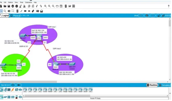
Figura 2. Simulación de escenario 1………..11
Figura 3. Comunicación Router 1……….17
Figura 4. Comunicación Router 2……….17
Figura 5. Comunicación Router 3...17
Figura 6. Escenario 2...18
Figura 7. Simulación del escenario 2...18
Figura 8. Configuración de DSL1...25
Figura 9. Configuración de DSL2………..26
Figura 10. Configuración de ALS1………...26
Figura 11. Configuración de ALS2………26
RESUMEN
Las redes pueden mejorar su desempeño a partir de la conmutación. La conmutación permite segmentar una red creando dominios de colisión con anchos de banda exclusivos para cada segmento pudiendo transmitir y recibir al mismo tiempo sin el retardo que provocarían las colisiones.
Los puentes, switches y routers dividen las redes en segmentos. Los puentes trabajan a nivel de software generando alta latencia, los routers utilizan gran cantidad de recursos, mientras que los switches lo hacen a nivel de hardware siendo tan rápidos como el medio lo exija.
Palabras Clave: cisco, router, enrutamiento, interconexión, red, interfaz, lan, dirección, internet,
configuración.
ABSTRACT
Networks can improve their performance from switching. The switching allows to segment a network by creating collision domains with exclusive bandwidths for each segment, being able to transmit and receive at the same time without the delay that the collisions would cause.
Bridges, switches and routers divide networks into segments. The bridges work at the software level generating high latency, the routers use a lot of resources, while the switches do it at the hardware level being as fast as the medium demands.
INTRODUCCIÓN
El presente trabajo se realiza para cumplir los objetivos de habilidades practicas del diplomado de profundización en redes Cisco Networking, y como requisito para grado de Ingeniero en Telecomunicaciones de la universidad Nacional Abierta y a distancia UNAD.
Este Trabajo es sobre dos topologías de redes con diferentes exigencias de conexión y condiciones de implementación, se realizó por medio de simulación en el software Packet Tracer, el cual está diseñado para el trabajo de redes con router’s y switches de la tecnología Cisco.
DESARROLLO
1. ESCENARIO 1
Parte 1: Configuración del escenario propuesto
Configurar las interfaces con las direcciones IPv4 e IPv6 que se muestran en la topología de red.
Figura 2. Simulación de escenario 1
BOGOTA
en config t
hostname BOGOTA ipv6 unicast-routing no ip domain-lookup line con 0
logging synchronous exec-timeout 0 0 exit
interface g0/0 exit
interface g0/0
ip address 192.168.110.1 255.255.255.0 ipv6 address 2001:db8:acad:110::1/64 no shutdown
exit
interface s0/0/0
exit BUCARAMANGA en config t hostname BUCARAMANGA ipv6 unicast-routing
no ip domain-lookup line con 0
logging synchronous exec-timeout 0 0 interface s0/0/0
ip address 192.168.9.2 255.255.255.252 ipv6 address 2001:db8:acad:90::2/64 ipv6 address fe80::2 link-local
no shutdown exit
interface s0/0/1
ip address 192.168.9.5 255.255.255.252 ipv6 address 2001:db8:acad:91::1/64 ipv6 address fe80::2 link-local
clock rate 128000 no shutdown exit
interface g0/0
ip address 192.168.2.1 255.255.255.0 ipv6 address 2001:db8:acad:b::1/64 no shutdown exit MEDELLIN en config t hostname MEDELLIN ipv6 unicast-routing no ip domain-lookup line con 0
logging synchronous exec-timeout 0 0 exit
interface s0/0/1
ip address 192.168.9.6 255.255.255.252 ipv6 address 2001:db8:acad:91::2/64 ipv6 address fe80::3 link-local
exit
interface g0/0
ip address 192.168.0.9 255.255.255.0 ipv6 address 2001:db8:acad:c::1/64 no shutdown
exit
2. Ajustar el ancho de banda a 128 kbps sobre cada uno de los enlaces seriales ubicados en R1, R2, y R3 y ajustar la velocidad de reloj de las conexiones de DCE según sea apropiado.
BOGOTA
en config t
interface s0/0/0 bandwidth 128 clock rate 128000 no shutdown exit BUCARAMANGA en config t interface s0/0/0 bandwidth 128 no shutdown exit interface s0/0/1 bandwidth 128 clock rate 128000 no shutdown exit MEDELLIN en config t interface s0/0/1 bandwidth 128 no shutdown exit
BUCARAMANGA
en config t
ipv4 unicast-routing router ospf 1
router-id 2.2.2.2 exit ipv6 unicast-routing router ospf1 router-id 2.2.2.2 exit MEDELLIN en config t router ospf 1 router-id 3.3.3.3 exit ipv6 unicast-routing router ospf1 router-id 3.3.3.3 exit
4. En R2, configurar la interfaz F0/0 en el área 1 de OSPF y la conexión serial entre R2 y R3 en OSPF área 0.
en config t
interface g0/0 ospf 1 ipv4 area 1 exit
interface s0/0/1 ospf 1 ipv4 area 0 exit
5. En R3, configurar la interfaz F0/0 y la conexión serial entre R2 y R3 en OSPF área 0.
en config t
interface g0/0 ospf 1 ipv4 area 1 ospf 1 ipv6 area 1 exit
ospf 1 ipv4 area 0 ospf 1 ipv6 area o exit
6. Configurar el área 1 como un área totalmente Stubby.
en config t router ospf 1
area 1 stub no-summary exit
ipv6 router ospf 1
area 1 stub no-summary exit
7. Propagar rutas por defecto de IPv4 y IPv6 en R3 al interior del dominio OSPFv3. Nota: Es importante tener en cuenta que una ruta por defecto es diferente a la definición de rutas estáticas.
en config t router ospf 1
default-information originate exit
ipv6 router ospf 1
default-information originate exit
8. Realizar la configuración del protocolo EIGRP para IPv4 como IPv6. Configurar la interfaz F0/0 de R1 y la conexión entre R1 y R2 para EIGRP con el sistema autónomo 101. Asegúrese de que el resumen automático está desactivado.
en config t
router eigrp 101
network 192.168.9.0 0.0.0.3 network 192.168.110.0 0.0.0.255 eigrp router-id 1.1.1.1
exit
9. Configurar las interfaces pasivas para EIGRP según sea apropiado.
en config t
interface g0/0 passive-interface no shutdown exit
10. En R2, configurar la redistribución mutua entre OSPF y EIGRP para IPv4 e IPv6. Asignar métricas apropiadas cuando sea necesario.
en config t
router eigrp 101
redistribute ospf 1 metric 1500 100 255 1 exit
ipv6 router eigrp 101
redistribute ospf 1 metric 1500 100 255 1 exit
11. En R2, de hacer publicidad de la ruta 192.168.3.0/24 a R1 mediante una lista de distribución y ACL.
en config t
router eigrp 101
redistribute ospf 1 metric 1500 100 255 1 exit
ipv6 router eigrp 101
redistribute ospf 1 metric 1500 100 255 1 exit
access-list 1 deny 192.168.3.0 0.0.0.255 access-list 1 permit any
exit
Parte 2: Verificar conectividad de red y control de la trayectoria.
a. Registrar las tablas de enrutamiento en cada uno de los routers, acorde con los parámetros de configuración establecidos en el escenario propuesto.
b. Verificar comunicación entre routers mediante el comando ping y traceroute
ping
Figura 3. Comunicación Router 1
Figura 4. Comunicación Router 2
Figura 5. Comunicación Router 3
c. Verificar que las rutas filtradas no están presentes en las tablas de enrutamiento de los routers correctas.
en
1. ESCENARIO 2
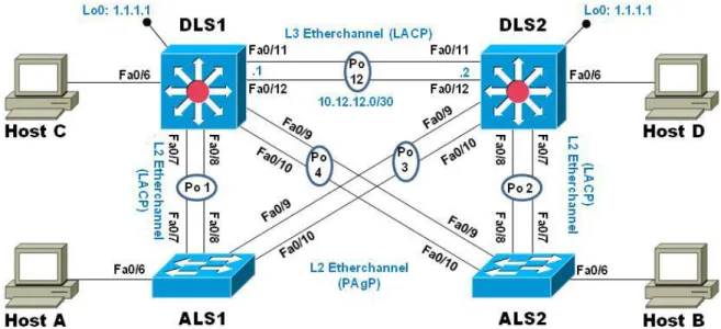
Figura 6. Escenario 2
PARTE 1: Configurar la red de acuerdo con las especificaciones.
a. Apagar todas las interfaces en cada switch.
enable config t
interface range f0/1-24, g0/1-2 shutdown
b. Asignar un nombre a cada switch acorde al escenario establecido
enable config t hostname
c. Configurar los puertos troncales y Port-channels tal como se muestra en el diagrama.
1) La conexión entre DLS1 y DLS2 será un EtherChannel capa-3 utilizando LACP. Para DLS1 se utilizará la dirección IP 10.12.12.1/30 y para DLS2 utilizará 10.12.12.2/30.
DSL1 en config t
interface port-channel 12 no switchport
ip address 10.12.12.1 255.255.255.252 exit
interface range fa0/11-12 no switchport
channel-group 12 mode active exit
DLS2 en config t
interface port-channel 12 no switchport
ip address 10.12.12.2 255.255.255.252 exit
interface range fa0/11-12 no switchport
2) Los Port-channels en las interfaces Fa0/7 y Fa0/8 utilizarán LACP.
DSL1 en config t
int ran fa0/7-8
switchport trunk encapsulation dotlq switchport mode trunk
channel-group 1 mode active no shutdown
exit
ASL1 en config t
int ran fa0/7-8
switchport mode trunk
channel-group 1 mode active no shutdown
exit
DSL2 en config
int ran fa0/7-8
switchport trunk encapsulation dotlq switchport mode trunk
channel-group 2 mode active no shutdown
exit
ASL2 en config
int ran fa0/7-8
switchport mode trunk
channel-group 2 mode active no shutdown
exit
3) Los Port-channels en las interfaces F0/9 y fa0/10 utilizará PAgP.
DLS1 en config
int ran fa0/9-10
switchport trunk encapsulation dotlq switchport mode trunk
no shutdown exit
ASL2 en config
int ran fa0/9-10
switchport mode trunk
channel-group 4 mode desirable no shutdown
exit
DSL2 en config
int ran fa0/9-10
switchport trunk encapsulation dotlq switchport mode trunk
channel-group 3 mode desirable no shutdown
exit
ALS1 en config
int ran fa0/9-10
switchport mode trunk
channel-group 3 mode desirable no shutdown
exit
4) Todos los puertos troncales serán asignados a la VLAN 800 como la VLAN nativa.
DSL1 en config t interface Po1
switchport trunk native vlan 800 exit
interface Po4
switchport trunk native vlan 800 exit
switchport trunk native vlan 800 exit
interface Po3
switchport trunk native vlan 800 exit
ASL2 en config t interface Po2
switchport trunk native vlan 800 exit
interface Po4
switchport trunk native vlan 800 exit
ASL1 en config t interface Po1
switchport trunk native vlan 800 exit
interface Po3
switchport trunk native vlan 800 exit
d. Configurar DLS1, ALS1, y ALS2 para utilizar VTP versión 3 1) Utilizar el nombre de dominio UNAD con la contraseña cisco123
DSL1 config t
vtp domain UNAD vtp pass cisco123
vtp version 3 ( aca produjo error ) vtp version 2
exit
ASL1 config t
vtp domain UNAD vtp pass cisco123 vtp version 2 exit
ASL2 config t
vtp version 2 exit
2) Configurar DLS1 como servidor principal para las VLAN.
config t
vtp mode server exit
3) Configurar ALS1 y ALS2 como clientes VTP.
ALS1 config t
vtp mode client exit
ALS2 config t
vtp mode client exit
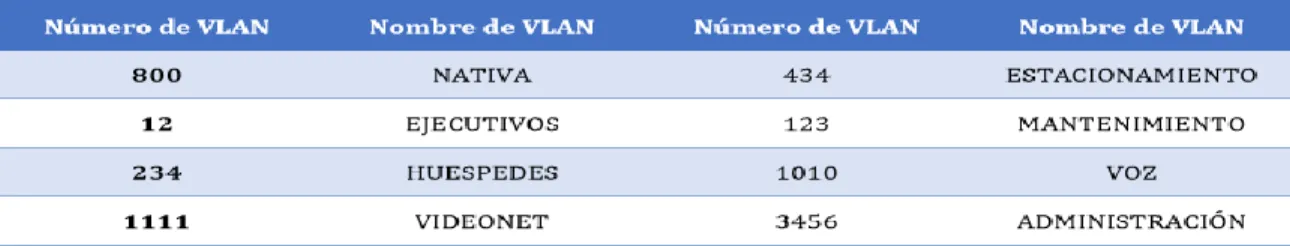
e. Configurar en el servidor principal las siguientes VLAN:
Tabla 1. VLAN para configurar en el servidor principal
DSL1 en config t vlan 800 name NATIVA vlan 12
name EJECUTIVOS vlan 234
name HUESPEDES vlan 1111 (genero error) vlan 11
name VIDEONET vlan 434
name ESTACIONAMIENTO vlan 123
name VOZ vlan 34
f. En DLS1, suspender la VLAN 434. en config t vlan 434 shutdown suspend
( aca no fue posible suspender la vlan 434, ya que ninguno de los comandos fue valido )
g. Configurar DLS2 en modo VTP transparente VTP utilizando VTP versión 2, y configurar en DLS2 las mismas VLAN que en DLS1.
en config t
vtp mode transparent exit DLS2 en config t vlan 800 name NATIVA vlan 12 name EJECUTIVOS vlan 234 name HUESPEDES vlan 11 name VIDEONET vlan 434 name ESTACIONAMIENTO vlan 123 name VOZ vlan 34 name ADMINISTRACION exi
h. Suspender VLAN 434 en DLS2.
en config t vlan 434 shutdown suspend
i. En DLS2, crear VLAN 567 con el nombre de CONTABILIDAD. La VLAN de CONTABILIDAD no podrá estar disponible en cualquier otro Switch de la red.
en config t vlan 567
name CONTABILIDAD exit
interface port-channel 2
switchport trunk allowed vlan except 567 exit
interface port-channel 3
switchport trunk allowed vlan except 567 exit
j. Configurar DLS1 como Spanning tree root para las VLAN 1, 12, 434, 800, 1010, 1111 y 3456 y como raíz secundaria para las VLAN 123 y 234.
en config t
spanning-tree vlan 1,12,434,800,101,11 root primary spanning-tree vlan 123,234 root secondary
exit
k. Configurar DLS2 como Spanning tree root para las VLAN 123 y 234 y como una raíz secundaria para las VLAN 12, 434, 800, 1010, 1111 y 3456.
en config t
spanning-tree vlan 123,234 root primary
spanning-tree vlan 12,434,800,101,11 root secondary exit
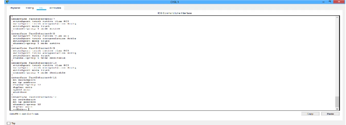
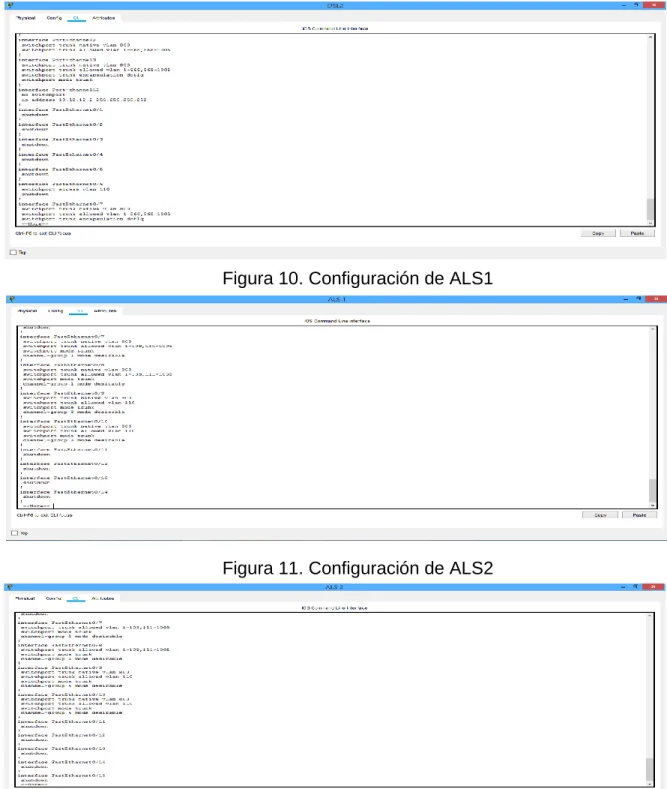
l. Configurar todos los puertos como troncales de tal forma que solamente las VLAN que se han creado se les permitirá circular a través de éstos puertos.
Figura 8. Configuración de DSL1
Figura 9. Configuración de DSL2
Figura 10. Configuración de ALS1
m. Configurar las siguientes interfaces como puertos de acceso, asignados a las VLAN de la siguiente manera:
Tabla 2. Interfaces para configurar como puertos de acceso
DLS1 en config t
interface fastethernet 0/6 switchport mode access switchport access vlan 34 no shutdown
exit
interface fastethernet 0/15 switchport mode access switchport access vlan 11 no shutdown
exit
DLS2 en config t
interface fastethernet 0/15 switchport mode access switchport access vlan 11 no shutdown
exit
interface fastethernet 0/16-18 switchport mode access switchport access vlan 567 no shutdown
exit
ALS1 en config t
interface fastethernet 0/6 switchport mode access switchport access vlan 123 no shutdown
exit
switchport mode access switchport access vlan 11 no shutdown
exit
ALS2 en config t
interface fastethernet 0/6 switchport mode access switchport access vlan 234 no shutdown
exit
interface fastethernet 0/15 switchport mode access switchport access vlan 11 no shutdown
exit
Part 2: conectividad de red de prueba y las opciones configuradas.
a. Verificar la existencia de las VLAN correctas en todos los switches y la asignación de puertos troncales y de acceso
en config t show vlan
b. Verificar que el EtherChannel entre DLS1 y ALS1 está configurado correctamente
en config t
show etherchannel summary
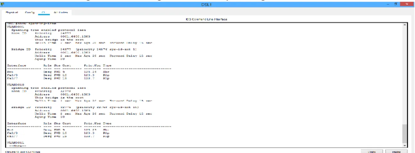
c. Verificar la configuración de Spanning tree entre DLS1 o DLS2 para cada VLAN.
En config t
show spanning-tree
CONCLUSIONES
• Los dos escenarios se realizaron en Packet Tracer, en el que se introdujeron diferentes comandos en los routers y switches dependiendo los protocolos y sus direcciones ipv4 e ipv6. Mediante los comandos show se verifico que los protocolos se han realizado correctamente y mediante los comandos ping que tenga conectividad entre los diferentes dispositivos.
• Se adquirió conocimientos sobre el Routing and Switching en la tecnología de redes CISCO, interactuando con plataformas simuladoras en implementación de redes.
BIBLIOGRAFÍA
(SWITCH) Foundation Learning Guide CCNP SWITCH 300-115. Recuperado de https://1drv.ms/b/s!AmIJYei-NT1IlnWR0hoMxgBNv1CJ
Spanning Tree Implementation Froom, R., Frahim, E. (2015). CISCO Press (Ed). Spanning Tree Implementation. Implementing Cisco IP Switched Networks (SWITCH) Foundation Learning Guide CCNP SWITCH 300-115. Recuperado de https://1drv.ms/b/s!AmIJYei-NT1IlnWR0hoMxgBNv1CJ
InterVLAN Routing Froom, R., Frahim, E. (2015). CISCO Press (Ed). InterVLAN Routing. Implementing Cisco IP Switched Networks (SWITCH) Foundation Learning Guide CCNP SWITCH 300-115. Recuperado de https://1drv.ms/b/s!AmIJYei-NT1IlnWR0hoMxgBNv1CJ
Teare, D., Vachon B., Graziani, R. (2015). CISCO Press (Ed). EIGRP Implementation. Implementing Cisco IP Routing (ROUTE) Foundation Learning Guide CCNP ROUTE 300-101. Recuperado de https://1drv.ms/b/s!AmIJYei- NT1IlnMfy2rhPZHwEoWx
Teare, D., Vachon B., Graziani, R. (2015). CISCO Press (Ed). OSPF Implementation. Implementing Cisco IP Routing (ROUTE) Foundation Learning Guide CCNP ROUTE 300-101. Recuperado de https://1drv.ms/b/s!AmIJYei- NT1IlnMfy2rhPZHwEoWx
Teare, D., Vachon B., Graziani, R. (2015). CISCO Press (Ed). Manipulating Routing Updates. Implementing Cisco IP Routing (ROUTE) Foundation Learning Guide CCNP ROUTE 300-101. Recuperado de https://1drv.ms/b/s!AmIJYei-
Froom, R., Frahim, E. (2015). CISCO Press (Ed). Spanning Tree Implementation. Implementing Cisco IP Switched Networks (SWITCH) Foundation Learning Guide CCNP SWITCH 300-115. Recuperado de https://1drv.ms/b/s!AmIJYei- NT1IlnWR0hoMxgBNv1CJ