DIPLOMADO DE PROFUNDIZACION CISCO PRUEBA DE HABILIDADES PRÁCTIAS CCNP
Héctor Alexander Quevedo Villamil
UNIVERSIDAD NACIONAL ABIERTA Y A DISTANCIA - UNAD
ESCUELA DE CIENCIAS BÁSICAS, TECNOLOGÍA E INGENIERÍA - ECBTI INGENIERÍA EN TELECOMUNICACIONES
DIPLOMADO DE PROFUNDIZACION CISCO PRUEBA DE HABILIDADES PRÁCTICAS CCNP
Héctor Alexander Quevedo Villamil
Diplomado de opción de grado presentado para optar el título de INGENIERO EN TELECOMUNICACIONES
DIRECTOR:
MSc. GERARDO GRANADOS ACUÑA
UNIVERSIDAD NACIONAL ABIERTA Y A DISTANCIA - UNAD ESCUELA DE CIENCIAS BÁSICAS, TECNOLOGÍA E INGENIERÍA - ECBTI
INGENIERÍA EN TELECOMUNICACIONES
3
NOTA DE ACEPTACIÓN
Firma del Presidente del Jurado
Firma del Jurado
Firma del Jurado
4
AGRADECIMIENTOS
Primero que todo, quiero dar gracias a Dios, ya que Él nos ha iluminado el camino y nos ha dado la fortaleza suficiente para alcanzar, con esfuerzo y dedicación, este galardón que tiene toda tu bendición.
5
CONTENIDO
AGRADECIMIENTOS ... 4
CONTENIDO ... 5
LISTA DE FIGURAS ... 6
LISTA DE TABLAS... 8
RESUMEN ... 9
ABSTRACT... 9
INTRODUCCIÓN ... 10
DESARROLLO ... 11
ESCENARIO 1 ... 11
ROUTER ... 11
ESCENARIO 2 ... 27
SWITCH ... 27
CONCLUSIONES ... 58
6
LISTA DE FIGURAS
Figura 1.Escenario 1 ... 11
Figura 2.Simulación de escenario 1 ... 12
Figura 3.Direcciones IPv4 e IPv6 ... 13
Figura 4.Direcciones IPv4 e IPv6 ... 14
Figura 5.Direcciones IPv4 e IPv6 ... 15
Figura 6.Ancho de banda ... 15
Figura 7.Ancho de banda ... 16
Figura 8.Ancho de banda ... 16
Figura 9.Direcciones OSPFv3 ... 17
Figura 10.Direcciones OSPFv3 ... 17
Figura 11.Area 1 de OSPF... 18
Figura 12.OSPF área 0 ... 19
Figura 13.Stubby ... 19
Figura 14.Rutas de IPv4 y IPv6 ... 20
Figura 15.Protocolo EIGRP... 20
Figura 16.Protocolo EIGRP... 21
Figura 17.Interfaces pasivas EIGRP ... 21
Figura 18.OSPF y EIGRP ... 22
Figura 19.Ruta 192.168.3.0/24 ... 22
Figura 20. Show ip route ... 23
Figura 21.Show ip route ... 23
Figura 22.Show ip route ... 24
Figura 23.Show ip route ... 24
Figura 24.Show ip route ... 25
Figura 25.Ping ... 25
Figura 26.Ping ... 26
Figura 27.Escenario 2 ... 27
Figura 28.Simulación de Escenario 2 ... 28
Figura 29.Apagado de puertos fastEthernet ... 29
Figura 30.Apagado de puertos GigabitEthernet ... 29
Figura 31.show interfaces Status ... 29
Figura 32.Apagado de puertos fastEthernet ... 30
Figura 33.Apagado de puertos GigabitEthernet ... 30
Figura 34.show interfaces Status ... 31
Figura 35.Apagado de puertos fastEtherne ... 32
Figura 36.Apagado de puertos GigabitEthernet ... 32
Figura 37.show interfaces Status ... 32
Figura 38.Apagado de puertos fastEthernet ... 33
Figura 39.Apagado de puertos GigabitEthernet ... 33
Figura 40.show interfaces Status ... 34
7
Figura 42.Nombre de switch DLS2 ... 35
Figura 43.Nombre de switch ASL1... 35
Figura 44.Nombre de switch ASL2... 35
Figura 45.Troncales y Port-channels DLS1 ... 36
Figura 46.Troncales y Port-channels DLS2 ... 36
Figura 47.Port-channels DLS1 ... 37
Figura 48.Port-channels DLS2 ... 37
Figura 49.Port-channels ASL1 ... 38
Figura 50.Port-channels ASL2 ... 38
Figura 51.interfaces F0/9 y fa0/10 DLS1 ... 39
Figura 52.interfaces F0/9 y fa0/10 DLS2 ... 39
Figura 53.interfaces F0/9 y fa0/10 ALS1 ... 39
Figura 54.interfaces F0/9 y fa0/10 ALS2 ... 40
Figura 55.VLAN 800 DLS1... 40
Figura 56.VLAN 800 DLS2... 41
Figura 57.VLAN 800 ASL1 ... 41
Figura 58.VLAN 800 ASL2 ... 42
Figura 59.Confi Contraseña DLS1 ... 42
Figura 60.VTP Mode Server DLS1 ... 43
Figura 61.Clientes VTP ASL1 ... 43
Figura 62.Clientes VTP ASL2 ... 43
Figura 63.Servidor VLAN DLS1 ... 45
Figura 64.Servidor VLAN DLS2 ... 45
Figura 65.VLAN 434 DLS1... 45
Figura 66.VLAN 434 DLS2... 46
Figura 67.VLAN 434 DLS2... 47
Figura 68.VLAN 567 DLS2... 47
Figura 69.Spanning tree DLS1 ... 47
Figura 70.Spanning tree DLS2 ... 48
Figura 71.troncales DLS1 ... 49
Figura 72.troncales DLS2 ... 50
Figura 73.troncales ALS2 ... 51
Figura 74.troncales ALS2 ... 51
Figura 75.Asignados a las VLAN DLS1... 52
Figura 76.Asignados a las VLAN DLS2... 53
Figura 77.Asignados a las VLAN ASL1 ... 53
Figura 78.Asignados a las VLAN ASL2 ... 54
Figura 79.show vlan DSL1 ... 54
Figura 80.show vlan DSL2 ... 55
Figura 81.show vlan ASL1 ... 55
Figura 82.show vlan ASL2 ... 56
Figura 83.show etherchannel DSL1 ... 56
Figura 84.show etherchannel ASL1 ... 57
8
LISTA DE TABLAS
Table 1.Interfaces Loopback para crear R1 ... 44 Table 2.Interfaces loopback para crear R2 ... 52
9
RESUMEN
Este proyecto consiste en el proceso de conceptualización de los diversos temas del área de networking y seguridad los cuales se apreciaron durante el Diplomado de CCNP, a su vez la aplicación práctica de los mismos en la elaboración de diferentes esquemas topológicos de red en los laboratorios para los módulos de CCNP ROUTE y CCNA SWITCH en ambientes de simulación elaborados en software tales como GSN3 Y Packet Tracer.
El objetivo principal es el enriquecimiento del estudiante en un área de profundización del área de telecomunicaciones que permita poseer una base práctica para el mejoramiento del pensamiento crítico y la capacidad de análisis proactivo sobre plataforma de red, el análisis de situaciones conflictivas que permitan al estudiante entender el funcionamiento de corta mediana y gran envergadura.
Palabras Clave: Enrutamiento, Conmutación, Seguridad, Red
ABSTRACT
This project consists of the process of conceptualization of the various topics of the area of networking and security which were appreciated during the CCNP Diploma, in turn the practical application of them in the development of different network topological schemes in laboratories to CCNP ROUTE and CCNA SWITCH modules in simulation environments developed in software such as GSN3 and Packet Tracer. The main objective is the enrichment of the student in an area of deepening of the telecommunications area that allows to have a practical basis for the improvement of critical thinking and the ability of proactive analysis on a network platform, the analysis of conflict situations that allow the student to understand The operation of short medium and large wingspan.
10
INTRODUCCIÓN
Durante esta actividad practica se desarrollaron dos escenarios (Uno con router y uno con switch) que permitían la configuración de diversos escenarios trabajados durante el diplomado, entre estos se encuentran las configuraciones básicas para ambos dispositivos (asignación de nombres, cableado, asignación de IP tanto IPv4 como IPv6, entre otros) así como la configuración de protocolos como Ethernet, OSPF, EIGRP, VTP, etc.
En este documento encontrará los comandos necesarios para realizar dichas configuraciones seguidas de la imagen que implementa esta en un software de diseño (GNS3, packet tracer o SmartLab) de acuerdo a las instrucciones dadas en la guía propuesta.
11
DESARROLLO
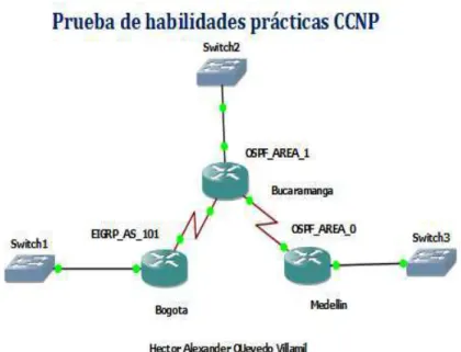
ESCENARIO 1
ROUTER
Una empresa de confecciones posee tres sucursales distribuidas en las ciudades de Bogotá, Medellín y Bucaramanga, en donde el estudiante será el administrador de la red, el cual deberá configurar e interconectar entre sí cada uno de los
dispositivos que forman parte del escenario, acorde con los lineamientos establecidos para el direccionamiento IP, protocolos de enrutamiento y demás aspectos que forman parte de la topología de red.
Configurar la topología de red, de acuerdo con las siguientes especificaciones.
12
Figura 2.Simulación de escenario 1
Parte 1: Configuración del escenario propuesto
1. Configurar las interfaces con las direcciones IPv4 e IPv6 que se muestran en la topología de red.
Router 1 EIGRP_AS_101 no ip domain-lookup line con 0
logging synchronous exec-timeout 0 0 hostname EIGRP
interface gigabitEthernet0/0
ip address 192.168.110.1 255.255.255.0 ipv6 address 2001:db8:acad:110::1/64 speed auto
duplex auto interface serial1/0
13
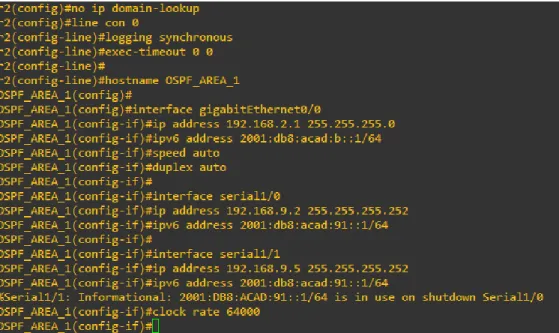
Figura 3.Direcciones IPv4 e IPv6
Router 1 OSPF_AREA_1 no ip domain-lookup line con 0
logging synchronous exec-timeout 0 0
hostname OSPF_AREA_1 interface gigabitEthernet0/0
ip address 192.168.2.1 255.255.255.0 ipv6 address 2001:db8:acad:b::1/64 speed auto
duplex auto interface serial1/0
ip address 192.168.9.2 255.255.255.252 ipv6 address 2001:db8:acad:91::1/64 interface serial1/1
14
Figura 4.Direcciones IPv4 e IPv6
Router 1 OSPF_AREA_0 no ip domain-lookup line con 0
logging synchronous exec-timeout 0 0
hostname OSPF_AREA_0 interface gigabitEthernet0/0
ip address 192.168.3.1 255.255.255.0 ipv6 address 2001:db8:acad:c::1/64 speed auto
duplex auto interface serial1/1
15
Figura 5.Direcciones IPv4 e IPv6
2. Ajustar el ancho de banda a 128 kbps sobre cada uno de los enlaces seriales ubicados en R1, R2, y R3 y ajustar la velocidad de reloj de las conexiones de DCE según sea apropiado.
Router 1 EIGRP_AS_101 interface serial1/0
bandwidth 128
Figura 6.Ancho de banda
Router 1 OSPF_AREA_1 interface serial1/0
16
Figura 7.Ancho de banda
Router 1 OSPF_AREA_0 interface serial1/1
bandwidth 128
Figura 8.Ancho de banda
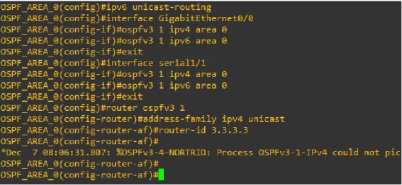
3. En R2 y R3 configurar las familias de direcciones OSPFv3 para IPv4 e IPv6. Utilice el identificador de enrutamiento 2.2.2.2 en R2 y 3.3.3.3 en R3 para ambas familias de direcciones.
Router 1 OSPF_AREA_1 ipv6 unicast-routing
interface GigabitEthernet0/0 ospfv3 1 ipv4 area 1
ospfv3 1 ipv6 area 1 exit
interface serial 1/0 ospfv3 1 ipv4 area 1 ospfv3 1 ipv6 area 1 exit
router ospfv3 1
17
Figura 9.Direcciones OSPFv3
Router 1 OSPF_AREA_0
ipv6 unicast-routing
interface GigabitEthernet0/0 ospfv3 1 ipv4 area 0
ospfv3 1 ipv6 area 0 exit
interface serial1/1 ospfv3 1 ipv4 area 0 ospfv3 1 ipv6 area 0 exit
router ospfv3 1
address-family ipv4 unicast router-id 3.3.3.3
18
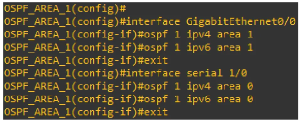
4. En R2, configurar la interfaz F0/0 en el área 1 de OSPF y la conexión serial entre R2 y R3 en OSPF área 0.
Router 1 OSPF_AREA_1
interface GigabitEthernet0/0 ospf 1 ipv4 area 1
ospf 1 ipv6 area 1 exit
interface serial 1/0 ospf 1 ipv4 area 0 ospf 1 ipv6 area 0 exit
Figura 11.Area 1 de OSPF
5. En R3, configurar la interfaz F0/0 y la conexión serial entre R2 y R3 en OSPF área 0.
Router 1 OSPF_AREA_0 interface GigabitEthernet0/0 ospf 1 ipv4 area 1
ospf 1 ipv6 area 1 exit
19
Figura 12.OSPF área 0
6. Configurar el área 1 como un área totalmente Stubby.
Router 1 OSPF_AREA_1
router ospfv3 1
area 1 stub no-summary
Figura 13.Stubby
7. Propagar rutas por defecto de IPv4 y IPv6 en R3 al interior del dominio OSPFv3. Nota: Es importante tener en cuenta que una ruta por defecto es diferente a la definición de rutas estáticas.
Router 1 OSPF_AREA_0
ip route 0.0.0.0 0.0.0.0 192.168.9.5 ipv6 route ::/0 2001:DB8:ACAD:91::1 router ospfv3 1
address-family ipv4 unicast default-information originate exit-address-family
address-family ipv6 unicast default-information originate exit-address-family
20
Figura 14.Rutas de IPv4 y IPv6
8. Realizar la configuración del protocolo EIGRP para IPv4 como IPv6. Configurar la interfaz F0/0 de R1 y la conexión entre R1 y R2 para EIGRP con el sistema autónomo 101. Asegúrese de que el resumen automático está desactivado.
Router 1 EIGRP_AS_101 ipv6 unicast-routing router eigrp 101 no auto-summary network 192.168.0.0 no shutdown
exit
interface g0/0 ipv6 eigrp 1 exit
interface s1/0 ipv6 eigrp 101 exit
21
Router 1 OSPF_AREA_1 ipv6 unicast-routing router eigrp 101 no auto-summary network 192.168.0.0 no shutdown
interface s1/0 ipv6 eigrp 101 exit
Figura 16.Protocolo EIGRP
9. Configurar las interfaces pasivas para EIGRP según sea apropiado.
Router 1 EIGRP_AS_101 router eigrp 101
passive-interface serial1/1 end
Figura 17.Interfaces pasivas EIGRP
10. En R2, configurar la redistribución mutua entre OSPF y EIGRP para IPv4 e IPv6. Asignar métricas apropiadas cuando sea necesario.
Router 1 OSPF_AREA_1 router ospf 1
redistribute eigrp 101 subnets exit
22
redistribute ospf 1 metric 10000 100 255 1 1500 default-metric 10000 100 255 1 1500
redistribute ospf 1 end
Figura 18.OSPF y EIGRP
11. En R2, de hacer publicidad de la ruta 192.168.3.0/24 a R1 mediante una lista de distribución y ACL.
Router 1 OSPF_AREA_1
access-list 1 permit host 192.168.9.1 end
Figura 19.Ruta 192.168.3.0/24
Parte 2: Verificar conectividad de red y control de la trayectoria.
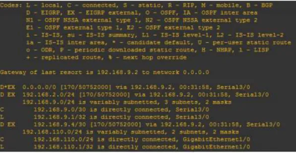
a. Registrar las tablas de enrutamiento en cada uno de los routers, acorde con los parámetros de configuración establecidos en el escenario propuesto.
#Enable
23
Router 1 EIGRP_AS_101
Figura 20. Show ip route
24
Router 1 OSPF_AREA_1
Figura 22.Show ip route
25
Router 1 OSPF_AREA_0
Figura 24.Show ip route
b. Verificar comunicación entre routers mediante el comando ping y traceroute
R1 Router 1 EIGRP_AS_101
26
Router 1 OSPF_AREA_1
Figura 26.Ping
Router 1 OSPF_AREA_0
27
ESCENARIO 2 .
SWITCH
Una empresa de comunicaciones presenta una estructura Core acorde a la topología de red, en donde el estudiante será el administrador de la red, el cual deberá configurar e interconectar entre sí cada uno de los dispositivos que forman parte del escenario, acorde con los lineamientos establecidos para el
direccionamiento IP, etherchannels, VLANs y demás aspectos que forman parte del escenario propuesto.
28
Figura 28.Simulación de Escenario 2
Parte 1: Configurar la red de acuerdo con las especificaciones.
a. Apagar todas las interfaces en cada switch.
Switch DLS1 configureterminal noipdomain-lookup linecon0
loggingsynchronous exec-timeout00 exit
interfacerangefastEthernet0/1-24 shutdown
29
Figura 29.Apagado de puertos fastEthernet
interfaceRangeGigabitEthernet0/1-2 shutdown
Figura 30.Apagado de puertos GigabitEthernet
Figura 31.show interfaces Status
30
linecon0
loggingsynchronous exec-timeout00 exit
interfacerangefastEthernet0/1-24 shutdown
exit
Figura 32.Apagado de puertos fastEthernet
interfaceRangeGigabitEthernet0/1-2 shutdown
31
Figura 34.show interfaces Status
Switch ALS1 configureterminal noipdomain-lookup linecon0
loggingsynchronous exec-timeout00 exit
interfacerangefastEthernet0/1-24 shutdown
32
Figura 35.Apagado de puertos fastEtherne
interfaceRangeGigabitEthernet0/1-2 shutdown
Figura 36.Apagado de puertos GigabitEthernet
33
Switch ALS2
configureterminal noipdomain-lookup linecon0
loggingsynchronous exec-timeout00 exit
interfacerangefastEthernet0/1-24 shutdown
exit
Figura 38.Apagado de puertos fastEthernet
interfaceRangeGigabitEthernet0/1-2 shutdown
34
Figura 40.show interfaces Status
b. Asignar un nombre a cada switch acorde al escenario establecido.
Switch DLS1 DLS1
configureterminal hostnameDSL1 end
wr
Figura 41.Nombre de switch DLS1
35
end wr
Figura 42.Nombre de switch DLS2
Switch ALS1 configureterminal hostnameASL1 end
wr
Figura 43.Nombre de switch ASL1
Switch ALS2 configureterminal hostnameASL2 end
wr
Figura 44.Nombre de switch ASL2
c. Configurar los puertos troncales y Port-channels tal como se muestra en el diagrama.
36
Switch DLS1 interfacevlan800
ipaddress10.12.12.1255.255.255.252 interfacerangef0/11-12
channel-protocollacp
channel-group2modeactive noshutdown
Figura 45.Troncales y Port-channels DLS1
Switch DLS2 interfacevlan800
ipaddress10.12.12.2255.255.255.252 interfacerangef0/11-12
channel-protocollacp
channel-group2modeactive noshutdown
Figura 46.Troncales y Port-channels DLS2
2) Los Port-channels en las interfaces Fa0/7 y Fa0/8 utilizarán LACP.
Switch DLS1
interfacerangef0/7-8 channel-protocollacp
channel-group2modeactive noshutdown
37
Figura 47.Port-channels DLS1
Switch DLS2
interfacerangef0/7-8 channel-protocollacp
channel-group2modeactive noshutdown
end
Figura 48.Port-channels DLS2
Switch ALS1
interfacerangef0/7-8 channel-protocollacp
channel-group2modeactive noshutdown
38
Figura 49.Port-channels ASL1
Switch ALS2
interfacerangef0/7-8 channel-protocollacp
channel-group2modeactive noshutdown
end
Figura 50.Port-channels ASL2
3) Los Port-channels en las interfaces F0/9 y fa0/10 utilizará PAgP.
Switch DLS1
interfacerangef0/9-10 channel-protocolpagp
channel-group2modedesirable noshutdown
39
Figura 51.interfaces F0/9 y fa0/10 DLS1
Switch DLS2
interfacerangef0/9-10 channel-protocolpagp
channel-group2modedesirable noshutdown
end
Figura 52.interfaces F0/9 y fa0/10 DLS2
Switch ALS1
interfacerangef0/9-10 channel-protocolpagp
channel-group2modedesirable noshutdown
end
40 Switch ALS2 interfacerangef0/9-10 channel-protocolpagp channel-group2modedesirable noshutdown end
Figura 54.interfaces F0/9 y fa0/10 ALS2
4) Todos los puertos troncales serán asignados a la VLAN 800 como la VLAN nativa. Switch DLS1 intranf0/7-12 switchporttrunkencapdot1q switchporttrunknativevlan800 switchportmodetrunk switchportnonegotiate noshut exit
Figura 55.VLAN 800 DLS1
41
Figura 56.VLAN 800 DLS2
Switch ALS1 intranf0/7-10
switchporttrunkencapdot1q switchporttrunknativevlan800 switchportmodetrunk
switchportnonegotiate noshut
exit
Figura 57.VLAN 800 ASL1
Switch ALS2 intranf0/7-10
switchporttrunkencapdot1q switchporttrunknativevlan800 switchportmodetrunk
switchportnonegotiate noshut
42
Figura 58.VLAN 800 ASL2
d. Configurar DLS1, ALS1, y ALS2 para utilizar VTP versión 3
1) Utilizar el nombre de dominio UNAD con la contraseña cisco123
Switch DLS1 conft
vtpdomainUNAD vtppasswordcisco123 end
Figura 59.Confi Contraseña DLS1
2) Configurar DLS1 como servidor principal para las VLAN.
Switch DLS1 conft
43
vtpmodeserver end
vtpprimarymst
Figura 60.VTP Mode Server DLS1
3) Configurar ALS1 y ALS2 como clientes VTP.
Switch ALS1
spanning-treemodepvst vtpversion2
vtpmodeclient end
Figura 61.Clientes VTP ASL1
Switch ALS1
spanning-treemodemst vtpversion3
vtpmodeclientmst end
44
e. Configurar en el servidor principal las siguientes VLAN:
Table 1.Interfaces Loopback para crear R1
Número de
VLAN Nombre de VLAN
Número de
VLAN Nombre de VLAN
800 NATIVA 434 ESTACIONAMIENTO
12 EJECUTIVOS 123 MANTENIMIENTO
234 HUESPEDES 1010 VOZ
1111 VIDEONET 3456 ADMINISTRACIÓN
45
Figura 63.Servidor VLAN DLS1
Switch DLS1
Figura 64.Servidor VLAN DLS2
f. En DLS1, suspender la VLAN 434.
Switch DLS1 vlan434
nameESTACIONAMIENTO statesuspend
exit
Figura 65.VLAN 434 DLS1
g. Configurar DLS2 en modo VTP transparente VTP utilizando VTP versión 2, y configurar en DLS2 las mismas VLAN que en DLS1.
Switch DLS2 vtpversion2
vtpmodetransparent vlan800
46
exit vlan12
nameEJECUTIVOS exit
vlan234
nameHUESPEDES exit
vlan1111
nameVIDEONET exit
vlan123
nameMANTENIMIENTO exit
vlan1010 nameVOZ exit
vlan3456
nameADMINISTRACION exit
Figura 66.VLAN 434 DLS2
h. Suspender VLAN 434 en DLS2.
47
vlan434
nameESTACIONAMIENTO statesuspend
exit
Figura 67.VLAN 434 DLS2
i. En DLS2, crear VLAN 567 con el nombre de CONTABILIDAD. La VLAN de CONTABILIDAD no podrá estar disponible en cualquier otro Switch de la red. Switch DLS2
vlan567
private-vlanisolated nameCONTABILIDAD exit
Figura 68.VLAN 567 DLS2
j. Configurar DLS1 como Spanning tree root para las VLAN 1, 12, 434, 800, 1010, 1111 y 3456 y como raíz secundaria para las VLAN 123 y 234.
Switch DLS1
spanning-tree vlan 123 root primary spanning-tree vlan 234 root primary spanning-tree vlan 12 root secondary spanning-tree vlan 434 root secondary spanning-tree vlan 800 root secondary spanning-tree vlan 1010 root secondary spanning-tree vlan 1111 root secondary spanning-tree vlan 3456 root secondary
48
k. Configurar DLS2 como Spanning tree root para las VLAN 123 y 234 y como una raíz secundaria para las VLAN 12, 434, 800, 1010, 1111 y 3456.
Switch DLS2
spanning-treevlan123rootprimary spanning-treevlan234rootprimary spanning-treevlan12rootsecondary spanning-treevlan434rootsecondary spanning-treevlan800rootsecondary spanning-treevlan1010rootsecondary spanning-treevlan1111rootsecondary spanning-treevlan3456rootsecondary
Figura 70.Spanning tree DLS2
l. Configurar todos los puertos como troncales de tal forma que solamente las VLAN que se han creado se les permitirá circular a través de éstos puertos. Switch DLS1
int ran f0/7-12
switchport trunk encap dot1q switchport trunk native vlan 800 switchport mode trunk
exit
49
Figura 71.troncales DLS1
Switch DLS2 int ran f0/7-12
switchport trunk encap dot1q switchport trunk native vlan 800 switchport mode trunk
50
Figura 72.troncales DLS2
Switch ALS1 int ran f0/7-12
switchport trunk allowed vlan 800 switchport trunk native vlan 800 switchport mode trunk
51
Figura 73.troncales ALS2
Switch ALS2 intranf0/7-12
switchporttrunkencapdot1q switchporttrunknativevlan800 switchportmodetrunk
exit
Figura 74.troncales ALS2
52 Table 2.Interfaces loopback para crear R2
Interfaz DLS1 DLS2 ALS1 ALS2
Interfaz Fa0/6 3456 12 , 1010 123, 1010 234
Interfaz Fa0/15 1111 1111 1111 1111
Interfaces F0 /16-18 567
Switch DLS1
interface fastethernet0/6 switchport access vlan 3456 no sh
interface fastethernet0/15 switchport access vlan 111 no sh
end
Figura 75.Asignados a las VLAN DLS1
Switch DLS2
interface fastethernet0/6 switchport access vlan 12 switchport access vlan 1010 no sh
interface fastethernet0/15 switchport access vlan 111 no sh
int ran f0/16-18
switchport access vlan 567 no sh
53
Figura 76.Asignados a las VLAN DLS2
Switch ALS1
interface fastethernet0/6 switchport access vlan 123 switchport access vlan 101 no sh
interface fastethernet0/15 switchport access vlan 111 no sh
end
54
Switch ALS2
interface fastethernet0/6 switchport access vlan 234 no sh
interface fastethernet0/15 switchport access vlan 111 no sh
end
Figura 78.Asignados a las VLAN ASL2
Part 2: conectividad de red de prueba y las opciones configuradas.
a. Verificar la existencia de las VLAN correctas en todos los switches y la asignación de puertos troncales y de acceso
show vlan brief
55
Figura 80.show vlan DSL2
56
Figura 82.show vlan ASL2
b. Verificar que el EtherChannel entre DLS1 y ALS1 está configurado correctamente
#show etherchannel summary
57
Figura 84.show etherchannel ASL1
c. Verificar la configuración de Spanning tree entre DLS1 o DLS2 para cada VLAN.
show spanning-tree
Figura 85.show etherchannel
58
CONCLUSIONES
HRSP es un protocolo propiedad de CISCO que permite crear routers redundantes y validar el estado de los routers para el envío, por cuanto contribuye a la fidelidad y disponibilidad de la red, esto teniendo en cuenta que el camino de información no se ve interrumpido pues esta puede encontrar otra ruta para llegar a su destino. EIGRP es un protocolo de enrutamiento propiedad de CISCO, permite configurar redes libres de bucles, realizar convergencia rápida, entre otras, además de soportar diferentes dispositivos mediante una configuración sencilla y utilizando ancho de banda reducido.
OSPFv3 es un protocolo de enrutamiento que entre otras cosas permite subdividir la red en áreas, una de sus ventajas es la actualización automática de las tablas de enrutamiento, actualmente cuenta con tres versiones, siendo la tercera que permite la inclusión de IPv6.
VTP es un protocolo propietario de Cisco el cual contribuye con la administración de la red, entre otras cosas permite distribuir una VLAN a toda la red sin que sea necesario realizar la configuración de esta en cada uno de los dispositivos, la versión más reciente es la 3 la cual solo está disponible en Catalyst IOS.
Mediante las VLAN (Red de área local virtual) se crean redes independientes, las cuales no son físicas por cuanto no involucran un ajuste del cableado estructurado, sino que se realizan de manera lógica en el dispositivo, permiten disminuir el tamaño del dominio de difusión y contribuyen con la administración de la red pues su objetivo es crear secciones pequeñas, permitiendo enviar información o actualizaciones a un segmento en particular.
Un enlace punto a punto entre dos dispositivos de red, es un enlace troncal que puede transportar más de una VLAN sin que llegue a pertenecer a una VLAN específica, los switch cisco admiten IEEE 802.1Q que facilitan la coordinación de estos enlaces
Las VLAN pueden dividirse en dos, las VLAN estáticas que cuentan con un puerto asociado y las dinámicas, las cuales desarrollan su propia configuración.
59
BIBLIOGRÁFIA
Teare, D., Vachon B., Graziani, R. (2015). CISCO Press (Ed). Basic Network and Routing Concepts.
Implementing Cisco IP Routing (ROUTE) Foundation Learning Guide CCNP ROUTE 300-101.
Recuperado dehttps://1drv.ms/b/s!AmIJYei-NT1IlnMfy2rhPZHwEoWx
Teare, D., Vachon B., Graziani, R. (2015). CISCO Press (Ed). EIGRP Implementation. Implementing Cisco IP Routing (ROUTE) Foundation Learning Guide CCNP ROUTE 300-101. Recuperado de https://1drv.ms/b/s!AmIJYei-NT1IlnMfy2rhPZHwEoWx
Teare, D., Vachon B., Graziani, R. (2015). CISCO Press (Ed). OSPF Implementation. Implementing Cisco
IP Routing (ROUTE) Foundation Learning Guide CCNP ROUTE 300-101. Recuperado de https://1drv.ms/b/s!AmIJYei-NT1IlnMfy2rhPZHwEoWx
Teare, D., Vachon B., Graziani, R. (2015). CISCO Press (Ed). Manipulating Routing Updates. Implementing Cisco IP Routing (ROUTE) Foundation Learning Guide CCNP ROUTE 300-101. Recuperado dehttps://1drv.ms/b/s!AmIJYei-NT1IlnMfy2rhPZHwEoWx
Teare, D., Vachon B., Graziani, R. (2015). CISCO Press (Ed). Path Control Implementation. Implementing Cisco IP Routing (ROUTE) Foundation Learning Guide CCNP ROUTE 300-101. Recuperado de https://1drv.ms/b/s!AmIJYei-NT1IlnMfy2rhPZHwEoWx
Teare, D., Vachon B., Graziani, R. (2015). CISCO Press (Ed). Implementing a Border Gateway Protocol (BGP) Solution for ISP Connectivity. Implementing Cisco IP Routing (ROUTE) Foundation Learning
Guide CCNP ROUTE 300-101. Recuperado de https://1drv.ms/b/s!AmIJYei-NT1IlnMfy2rhPZHwEoWx
Teare, D., Vachon B., Graziani, R. (2015). CISCO Press (Ed). Implementing Routing Facilities for Branch
Offices and Mobile Workers. Implementing Cisco IP Routing (ROUTE) Foundation Learning Guide
CCNP ROUTE 300-101. Recuperado de https://1drv.ms/b/s!AmIJYei-NT1IlnMfy2rhPZHwEoWx
Teare, D., Vachon B., Graziani, R. (2015). CISCO Press (Ed). Implementing IPv6 in the Enterprise Network. Implementing Cisco IP Routing (ROUTE) Foundation Learning Guide CCNP ROUTE 300-
101. Recuperado dehttps://1drv.ms/b/s!AmIJYei-NT1IlnMfy2rhPZHwEoWx
Froom, R., Frahim, E. (2015). CISCO Press (Ed). Fundamentals Review. Implementing Cisco IP Switched
60
Froom, R., Frahim, E. (2015). CISCO Press (Ed). Campus Network Design Fundamentals. Implementing Cisco IP Switched Networks (SWITCH) Foundation Learning Guide CCNP SWITCH 300-115.
Recuperado dehttps://1drv.ms/b/s!AmIJYei-NT1IlnWR0hoMxgBNv1CJ
Froom, R., Frahim, E. (2015). CISCO Press (Ed). Spanning Tree Implementation. Implementing Cisco IP Switched Networks (SWITCH) Foundation Learning Guide CCNP SWITCH 300-115. Recuperado dehttps://1drv.ms/b/s!AmIJYei-NT1IlnWR0hoMxgBNv1CJ
Froom, R., Frahim, E. (2015). CISCO Press (Ed). InterVLAN Routing. Implementing Cisco IP Switched
Networks (SWITCH) Foundation Learning Guide CCNP SWITCH 300-115. Recuperado dehttps://1drv.ms/b/s!AmIJYei-NT1IlnWR0hoMxgBNv1CJ
Froom, R., Frahim, E. (2015). CISCO Press (Ed). First Hop Redundancy Protocols. Implementing Cisco IP Switched Networks (SWITCH) Foundation Learning Guide CCNP SWITCH 300-115. Recuperado dehttps://1drv.ms/b/s!AmIJYei-NT1IlnWR0hoMxgBNv1CJ
Froom, R., Frahim, E. (2015). CISCO Press (Ed). Network Management. Implementing Cisco IP Switched
Networks (SWITCH) Foundation Learning Guide CCNP SWITCH 300-115. Recuperado de https://1drv.ms/b/s!AmIJYei-NT1IlnWR0hoMxgBNv1CJ
Froom, R., Frahim, E. (2015). CISCO Press (Ed). Switching Features and Technologies. Implementing Cisco IP Switched Networks (SWITCH) Foundation Learning Guide CCNP SWITCH 300-115.
Recuperado dehttps://1drv.ms/b/s!AmIJYei-NT1IlnWR0hoMxgBNv1CJ
Normas Icontec 2018 para trabajos escritos | mundonets. (2018). Recuperado de
https://www.mundonets.com/normas-icontec/
Normas ICONTEC 2016 para crear trabajos escritos - Tutorial. (2018). Recuperado de