EVALUACION FINAL
PRUEBA DE HABILIDADES PRACTICAS CCNP
EDWIN FABIAN BAUTISTA ESCOBAR
UNIVERSIDAD NACIONAL ABIERTA Y A DISTANCIA UNAD
INGENIERIA EN TELECOMUNICACIONES
DIPLOMADO CISCO CCNP
BOGOTA
EVALUACION PRUEBA DE HABILIDADES PRACTICAS CCNP
EDWIN FABIAN BAUTISTA ESCOBAR
Diplomado de proundizacion cisco CCNP prueba de
Habilidades Prácticas para optar al titulo de
Ingeniero en Telecomunicaciones
Gerardo Granados Acuña
Magister en Telematica
UNIVERSIDAD NACIONAL ABIERTA Y A DISTANCIA UNAD
INGENIERIA EN TELECOMUNICACIONES
DIPLOMADO CISCO CCNP
BOGOTA
Nota de Aceptación
Jurado
Jurado
CONTENIDO
LISTADO DE TABLAS ... 5
LISTADO DE FIGURAS ... 6
GLOSARIO ... 7
RESUMEN ... 8
INTRODUCCION ... 9
DESARROLLO PRUEBA DE HABILIDADES ... 10
ESCENARIO 1 ... 10
ESCENARIO 2 ... 22
ESCENARIO 3 ... 40
CONCLUSIONES ... 61
LISTADO DE TABLAS
Tabla 1. Direccionamiento Interfaces loopback ... 14
Tabla 2. Direccionamiento Interfaces loopback ... 16
Tabla 3. Direccionamiento Escenario 2. ... 22
Tabla 4. Direccionamiento Vlans Escenario 3 ... 22
LISTADO DE FIGURAS
Figura 1. Topología Escenario 1………. ... 10
Figura 2. Resultado show ip route Router 3……….. ... 18
Figura 3. Resultado show ip route Router 1 ... 19
Figura 4. Resultado show ip route Router 5………. ... 21
Figura 5. Topología final packet tracer escenario 1. ... 21
Figura 6. Topología escenario 2 ... 22
Figura 7. Resultado show ip route Router 1 Escenario 2 ... 27
Figura 8. Resultado show ip route Router 2 Escenario 2 ... 28
Figura 9. Resultado show ip route Router 2 Escenario 2 ... 31
Figura 10. Resultado show ip route Router 3 Escenario 2 ... 32
Figura 11. Resultado show ip route Router 3 Escenario 2 ... 34
Figura 12. Resultado show ip route Router 4 Escenario 2 ... 36
Figura 13. Resultado show ip route Router 3 Escenario 2 ... 37
Figura 14. Resultado show ip route Router 4 Escenario 2 ... 38
Figura 15. Topología final Packet Tracer Escenario 2 ... 39
Figura 16. Topología Escenario 3 ... 40
Figura 17. Resultado show vtp status Switch 1. ... 42
Figura 18. Resultado show vtp status Switch 2... 22
Figura 19. Resultado show vtp status Switch 3... 44
Figura 20. Resultado show interfaces trunk Switch 1 ... 45
Figura 21. Resultado show interfaces trunk Switch 2 ... 46
Figura 21. Resultado show interfaces trunk Switch 1 ... 47
Figura 22. Resultado show interfaces trunk Switch 2 y 3 ... 48
Figura 23. Resultado show vlan Switch 2 ... 50
Figura 24. Resultado show vlan Switch 1 ... 51
Figura 25. Resultado show vlan Switch 3 ... 51
Figura 26. Configuracion Ip PCS Switch 1 ... 52
Figura 27. Configuracion Ip PCS Switch 2 ... 52
Figura 28. Configuracion Ip PCS Switch 4 ... 22
Figura 29. Resultado ping PC Switch 1 ... 56
Figura 30. Resultado ping PC Switch 2 ... 56
Figura 31. Resultado ping PC Switch 3 ... 56
Figura 32. Resultado ping Switch 1 ... 57
Figura 33. Resultado ping Switch 2 ... 57
Figura 34. Resultado ping Switch 3 ... 58
Figura 35. Resultado ping Switch 1 ... 58
Figura 36. Resultado ping Switch 2 ... 59
Figura 37. Resultado ping Switch 3 ... 59
Figura 38. Resultado ping Switch 1 ... 60
GLOSARIO
ROUTER: Dispositivo encargado de establecer la ruta para el que cada paquete
enviado desde un host llegue a su destino, este dispositivo segmenta dominios de
red.
SWITCH: Dispositivo que puede operar en capa de enlace de datos de modelo de
referencia OSI o en capa de red, interconecta varios host, segmenta dominios de
colisión.
PROTOCOLO DE ENRUTAMIENTO: Son las reglas que especifican como se
comunican los dispositivos de capa 3 entre sí, lo hacen distribuyendo la
información que les permite tomar decisiones a estos dispositivos.
HOST: Dispositivo conectado a una red, estos proveen o utilizan servicios de esta
red, normalmente nos referimos a los dispositivos de usuario final.
TOPOLOGIA DE RED: El mapa que muestra la disposición de una red, entre
estos sus nodos, conexiones etc.
LOOPBACK: Interfaz de red virtual, básicamente lo que hace es que por medio de
ella se redirige el tráfico de vuelta al equipo actual.
TABLA DE ENRUTAMIENTO: La parte donde se almacenan las rutas en los
diferentes dispositivos de enrutamiento, l origen de estas rutas puede ser de redes
conectadas directamente utas estáticas o protocolos de enrutamiento dinámico.
IGP: Protocolos de enrutamiento interno, estos protocolos se usa, para que los
vecinos interiores puedan intercambiar información de accesibilidad, unos
ejemplos de este tipo de protocolos son RIP y OSPF.
EGP: Este tipo de protocolos se diseña para intercambiar información entre
sistemas autónomos externos conectados a internet
VECINO: Router y switches conectados y que se comparten información entre sí,
normalmente conectados directamente.
VTP: VLAN Trunking Protocol, protocolo usado para configurar y administrar vlans
en equipos Cisco, permitiendo centralizar la administración de dichas vlans.
VLAN: Red de área local virtual, es un método para crear redes lógicas en una
misma red física, por ejemplo se usan cuando queremos separar recursos en
distintas áreas de una compañía.
DIRECCION IP: Número que identifica de manera lógica y jerárquica una interfaz
en un dispositivo que usa un protocolo IP.
RESUMEN
La prueba de habilidades como parte de las actividades evaluativas del diplomado
de profundización busca conocer el grado de apropiación de los conocimientos
que fueron dados a lo largo del curso CCNP, por este motivo se lleva a cabo el
desarrollo de 3 escenarios con diferentes configuraciones para validar los
conceptos aprendidos durante el curso.
El primero escenario, trata de un montaje con 5 routers en los cuales se
configuran los protocolos de enrutamiento distintos con el fin de validar la
propagación de las rutas entre diferentes protocolos de enrutamiento interno, se
validan las tablas de enrutamiento de los mismos.
Para el segundo escenario, se configuran las relaciones de vecinos en BGP, para
anunciar las diferentes rutas que se encuentran en los routers, esto como
demostración de una configuración de protocolo de enrutamiento exterior.
En el tercer escenario, se validan las configuraciones para switches tales como
VTP, DTP, se agregan VLANs y se verifica la conectividad entre los diferentes
hosts conectados en los distintos switches.
INTRODUCCION
En el presente documento se muestran los resultados de las configuraciones de
los dispositivos para los distintos escenarios propuestos como prueba del
aprendizaje obtenido a través del desarrollo del diplomado de profundización
CCNP Cisco, se dan a conocer los comandos de configuración usados en los
dispositivos, se muestran los pantallazos que arrojan los dispositivos al momento
de ingresar los comandos y también el resultado de los mismos.
1. DESARROLLO PRUEBA DE HABILIDADES
1.1 ESCENARIO 1
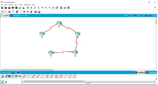
Figura 1. Topología Escenario 1
1. Aplique las configuraciones iniciales y los protocolos de enrutamiento para
los routers R1, R2, R3, R4 y R5 según el diagrama. No asigne passwords
en los routers. Configurar las interfaces con las direcciones que se
muestran en la topología de red.
En este punto en cada router se realiza la configuración de las interfaces,
se configura la Ip en cada una, en las interfaces DCE, se configura la
frecuencia de reloj, aparte de esto se realiza la configuración de los
diferentes protocolos de enrutamiento, para OSPF, el proceso será el OSPF
1 y el área 0, en EIGRP, el sistema autónomo será el 10, debemos recordar
que los routers 1 y 2 estarán configurados con el protocolo OSPF y los
router 4 y 5 estarán configurados con el protocolo EIGRP, el router 3 tendrá
una interfaz participando el proceso OSPF y una participando en EIGRP.
Configuración R1:
Router>enable
Router#configure terminal
Enter configuration commands, one per line. End with CNTL/Z. Router(config)#hostname R1
R1(config)#inter s0/0/0
R1(config-if)#clock rate 125000 R1(config-if)#no shutdown
%LINK-5-CHANGED: Interface Serial0/0/0, changed state to down R1(config-if)#exit
R1(config)#router ospf 1
R1(config-router)#network 10.103.12.0 0.0.0.255 % Incomplete command.
R1(config-router)#network 10.103.12.0 0.0.0.255 area 0 R1(config-router)#exit
R1(config)#
Configuración R2:
Router>enable
Router#configure terminal
Enter configuration commands, one per line. End with CNTL/Z. Router(config)#hostname R2
R2(config)#interfa s0/0/0
R2(config-if)#ip add 10.103.12.2 255.255.255.0 R2(config-if)#no shutdown
R2(config-if)#
%LINK-5-CHANGED: Interface Serial0/0/0, changed state to up
%LINEPROTO-5-UPDOWN: Line protocol on Interface Serial0/0/0, changed state to up
R2(config-if)#exit R2(config)#interfa s0/0/1
R2(config-if)#ip add 10.103.23.1 255.255.255.0 R2(config-if)#no shutdown
%LINK-5-CHANGED: Interface Serial0/0/1, changed state to down R2(config-if)#exit
R2(config)#router ospf 1
R2(config-router)#network 10.103.12.0 0.0.0.255 area 0 R2(config-router)#network 10.103.12.0 0.0.0.255 area 0
Configuración R3:
Router>enable
Enter configuration commands, one per line. End with CNTL/Z. Router(config)#hostname R3
R3(config)#interface s0/0/0
R3(config-if)#ip add 10.103.23.2 255.255.255.0 R3(config-if)#clock rate 125000
R3(config-if)#no shutdown
R3(config-if)#
%LINK-5-CHANGED: Interface Serial0/0/0, changed state to up
R3(config-if)#exit R3(config)#
%LINEPROTO-5-UPDOWN: Line protocol on Interface Serial0/0/0, changed state to up
R3(config)#interface s0/0/1
R3(config-if)#ip add 172.29.34.0 255.255.255.0
Bad mask /24 for address 172.29.34.0
R3(config-if)#ip add 172.29.34.1 255.255.255.0 R3(config-if)#no shutdown
%LINK-5-CHANGED: Interface Serial0/0/1, changed state to down
R3(config-if)#exit R3(config)#router ospf 1
R3(config-router)#network 10.103.23.0 0.0.0.255 area 0
R3(config-router)#exit R3(config)#
01:40:49: %OSPF-5-ADJCHG: Process 1, Nbr 10.103.23.1 on Serial0/0/0 from LOADING to FULL, Loading Done
R3(config)#router eigrp 10
R3(config-router)#network 172.29.34.0 0.0.0.255
R3(config-router)#exit R3(config)#
Configuración R4:
Router>enable
Router#configure terminal
Enter configuration commands, one per line. End with CNTL/Z. Router(config)#hostname R4
R4(config-if)#ip add 172.29.34.2 255.255.255. ^
% Invalid input detected at '^' marker.
R4(config-if)#ip add 172.29.34.2 255.255.255.0
R4(config-if)#no shutdown
R4(config-if)#
%LINK-5-CHANGED: Interface Serial0/0/0, changed state to up
%LINEPROTO-5-UPDOWN: Line protocol on Interface Serial0/0/0, changed state to up
R4(config-if)#exit
R4(config)#interface s0/0/1
R4(config-if)#ip add 172.29.45.2 255.255.255.0 R4(config-if)#no shutdown
%LINK-5-CHANGED: Interface Serial0/0/1, changed state to down R4(config-if)#exit
R4(config)#router eigrp 10
R4(config-router)#no auto-summary
R4(config-router)#network 172.29.34.0 0.0.0.255 R4(config-router)#
%DUAL-5-NBRCHANGE: IP-EIGRP 10: Neighbor 172.29.34.1 (Serial0/0/0) is up: new adjacency
R4(config-router)#network 172.29.45.0 0.0.0.255 R4(config-router)#exit
R4(config)#
Configuración R5:
Router>enable
Router#configure terminal
Enter configuration commands, one per line. End with CNTL/Z.
Router(config)#hostname R5 R5(config)#interfa s0/0/0
R5(config-if)#ip add 172.29.45.1 255.255.255.0
R5(config-if)#clock rate 125000 R5(config-if)#no shutdown
%LINK-5-CHANGED: Interface Serial0/0/0, changed state to up exit
R5(config)#
%LINEPROTO-5-UPDOWN: Line protocol on Interface Serial0/0/0, changed state to up
R5(config)#router eigrp 10
R5(config-router)#network 172.29.45.0 0.0.0.255 R5(config-router)#
%DUAL-5-NBRCHANGE: IP-EIGRP 10: Neighbor 172.29.45.2 (Serial0/0/0) is up: new adjacency
R5(config-router)#exit R5(config)#exit
2. Cree cuatro nuevas interfaces de Loopback en R1 utilizando la asignación
de direcciones 10.1.0.0/22 y configure esas interfaces para participar en el
área 0 de OSPF.
Con la dirección Ip dada, tomamos además 3 direcciones más para crear
las interfaces Loopback, se procede a crear las interfaces en el router,
luego se configuran dentro del proceso OSPF para que puedan participar
del mismo.
INTERFAZ
IP
Loopback 1 10.1.0.1/22
Loopback 2 10.2.0.1/22
Loopback 3 10.3.0.1/22
Loopback 4 10.4.0.1/22
Tabla 1. Direccionamiento Interfaces loopback
R1(config)#interface loopback 1
%LINK-5-CHANGED: Interface Loopback1, changed state to up
%LINEPROTO-5-UPDOWN: Line protocol on Interface Loopback1, changed state to up R1(config-if)#ip add 10.1.0.1 255.255.252.0
R1(config-if)#exit
R1(config)#interface loopback 2 R1(config-if)#
%LINEPROTO-5-UPDOWN: Line protocol on Interface Loopback2, changed state to up
R1(config-if)#ip add 10.2.0.1 255.255.252.0 R1(config-if)#exit
R1(config)#interface loopback 3
R1(config-if)#
%LINK-5-CHANGED: Interface Loopback3, changed state to up
%LINEPROTO-5-UPDOWN: Line protocol on Interface Loopback3, changed state to up
R1(config-if)#ip add 10.3.0.1 255.255.252.0
R1(config-if)#exit
R1(config)#interface loopback 4 R1(config-if)#
%LINK-5-CHANGED: Interface Loopback4, changed state to up
%LINEPROTO-5-UPDOWN: Line protocol on Interface Loopback4, changed state to up
ip add 10.4.0.1 255.255.252.0 R1(config-if)#exit
R1(config)#router ospf 1
R1(config-router)#network 10.103.12.0 0.0.0.255 area 0 R1(config-router)#network 10.1.0.0 0.0.3.255 area 0
R1(config-router)#network 10.2.0.0 0.0.3.255 area 0 R1(config-router)#network 10.3.0.0 0.0.3.255 area 0 R1(config-router)#network 10.4.0.0 0.0.3.255 area 0
R1(config-router)#exit
3. Cree cuatro nuevas interfaces de Loopback en R5 utilizando la asignación
de direcciones 172.5.0.0/22 y configure esas interfaces para participar en el
Sistema Autónomo EIGRP 10.
INTERFAZ
IP
Loopback 5 172.5.0.1/22
Loopback 6 172.6.0.1/22
Loopback 7 172.7.0.1/22
Loopback 8 172.8.0.1/22
Tabla 2. Direccionamiento Interfaces loopback
R5(config)#interface loopback 5 R5(config-if)#
%LINK-5-CHANGED: Interface Loopback5, changed state to up
%LINEPROTO-5-UPDOWN: Line protocol on Interface Loopback5, changed state to up R5(config-if)#ip add 172.5.0.1 255.255.252.0
R5(config-if)#exit
R5(config)#interface loopback 6 R5(config-if)#
%LINK-5-CHANGED: Interface Loopback6, changed state to up
%LINEPROTO-5-UPDOWN: Line protocol on Interface Loopback6, changed state to up
R5(config-if)#ip add 172.6.0.1 255.255.252.0 R5(config-if)#exit
R5(config)#interface loopback 7 R5(config-if)#
%LINK-5-CHANGED: Interface Loopback7, changed state to up
%LINEPROTO-5-UPDOWN: Line protocol on Interface Loopback7, changed state to up ip add 172.7.0.1 255.255.252.0
R5(config-if)#exit
R5(config)#interface loopback 8 R5(config-if)#
%LINK-5-CHANGED: Interface Loopback8, changed state to up
%LINEPROTO-5-UPDOWN: Line protocol on Interface Loopback8, changed state to up
R5(config-if)#ip add 172.8.0.1 255.255.252.0 R5(config-if)#exit
R5(config)#router eigrp 10
R5(config-router)#no auto-summary
R5(config-router)#network 172.6.0.0 0.0.3.255 R5(config-router)#network 172.7.0.0 0.0.3.255
R5(config-router)#network 172.8.0.0 0.0.3.255 R5(config-router)#exit
R5(config)#
4. Analice la tabla de enrutamiento de R3 y verifique que R3 está aprendiendo
las nuevas interfaces de Loopback mediante el comando show ip route.
Como se puede ver en el resultado del comando, el router por un lado está
aprendiendo las interfaces provenientes del R1 en OSPF O y por otro está
aprendiendo las interfaces provenientes de R5 en EIGRP D.
R3#show ip route
Codes: L - local, C - connected, S - static, R - RIP, M - mobile, B - BGP D - EIGRP, EX - EIGRP external, O - OSPF, IA - OSPF inter area N1 - OSPF NSSA external type 1, N2 - OSPF NSSA external type 2 E1 - OSPF external type 1, E2 - OSPF external type 2, E - EGP i - IS-IS, L1 - IS-IS level-1, L2 - IS-IS level-2, ia - IS-IS inter area * - candidate default, U - per-user static route, o - ODR
P - periodic downloaded static route
Gateway of last resort is not set
10.0.0.0/8 is variably subnetted, 7 subnets, 2 masks
O 10.1.0.1/32 [110/129] via 10.103.23.1, 00:22:00, Serial0/0/0 O 10.2.0.1/32 [110/129] via 10.103.23.1, 00:21:50, Serial0/0/0 O 10.3.0.1/32 [110/129] via 10.103.23.1, 00:21:50, Serial0/0/0 O 10.4.0.1/32 [110/129] via 10.103.23.1, 00:21:40, Serial0/0/0 O 10.103.12.0/24 [110/128] via 10.103.23.1, 01:16:33, Serial0/0/0 C 10.103.23.0/24 is directly connected, Serial0/0/0
L 10.103.23.2/32 is directly connected, Serial0/0/0 172.5.0.0/22 is subnetted, 1 subnets
D 172.5.0.0/22 [90/2809856] via 172.29.34.2, 00:13:14, Serial0/0/1 172.6.0.0/22 is subnetted, 1 subnets
D 172.6.0.0/22 [90/2809856] via 172.29.34.2, 00:13:09, Serial0/0/1 172.7.0.0/22 is subnetted, 1 subnets
D 172.7.0.0/22 [90/2809856] via 172.29.34.2, 00:13:05, Serial0/0/1 172.8.0.0/22 is subnetted, 1 subnets
D 172.8.0.0/22 [90/2809856] via 172.29.34.2, 00:13:02, Serial0/0/1 172.29.0.0/16 is variably subnetted, 3 subnets, 2 masks
C 172.29.34.0/24 is directly connected, Serial0/0/1 L 172.29.34.1/32 is directly connected, Serial0/0/1
Figura 2. Resultado show ip route Router 3.
5. Configure R3 para redistribuir las rutas EIGRP en OSPF usando el costo de
50000 y luego redistribuya las rutas OSPF en EIGRP usando un ancho de
banda T1 y 20,000 microsegundos de retardo.
Para este momento se toma en cuenta que el ancho de banda de un T1 es
de 1,544 Mbs si lo pasamos a Kbps que es como lo vamos a configurar nos
quedara en 1544 Kbps, para efectos prácticos lo dejaremos en 1500, esto
para redistribuir las rutas de OSPF en EIGRP, además podremos el delay
en 20000 microsegundos, la disponibilidad efectiva será de 255 y el
porcentaje de sobrecarga estará en 1. Para distribuir EIGRP en OSPF
usaremos un coste de 50000.
R3(config)#router eigrp 10
R3(config-router)#redistribute ospf 1 metric 1500 20000 255 1 1500 R3(config-router)#exit
R3(config)#router ospf 1
R3(config-router)#redistribute eigrp 10 metric 50000 subnets
R3(config-router)#exit R3(config)#
6. Verifique en R1 y R5 que las rutas del sistema autónomo opuesto existen
en su tabla de enrutamiento mediante el comando show ip route.
OSPF o EIGRP y son marcadas como rutas OSPF o EIGRP externas tipo
2.
Resultado R1:
R1#show ip route
Codes: L - local, C - connected, S - static, R - RIP, M - mobile, B - BGP D - EIGRP, EX - EIGRP external, O - OSPF, IA - OSPF inter area
N1 - OSPF NSSA external type 1, N2 - OSPF NSSA external type 2 E1 - OSPF external type 1, E2 - OSPF external type 2, E - EGP
i - IS-IS, L1 - IS-IS level-1, L2 - IS-IS level-2, ia - IS-IS inter area * - candidate default, U - per-user static route, o - ODR
P - periodic downloaded static route
Gateway of last resort is not set
10.0.0.0/8 is variably subnetted, 11 subnets, 3 masks C 10.1.0.0/22 is directly connected, Loopback1 L 10.1.0.1/32 is directly connected, Loopback1
C 10.2.0.0/22 is directly connected, Loopback2 L 10.2.0.1/32 is directly connected, Loopback2 C 10.3.0.0/22 is directly connected, Loopback3
L 10.3.0.1/32 is directly connected, Loopback3 C 10.4.0.0/22 is directly connected, Loopback4 L 10.4.0.1/32 is directly connected, Loopback4
C 10.103.12.0/24 is directly connected, Serial0/0/0 L 10.103.12.1/32 is directly connected, Serial0/0/0
O 10.103.23.0/24 [110/128] via 10.103.12.2, 01:50:38, Serial0/0/0 172.5.0.0/22 is subnetted, 1 subnets
O E2 172.5.0.0/22 [110/50000] via 10.103.12.2, 00:01:40, Serial0/0/0
172.6.0.0/22 is subnetted, 1 subnets
O E2 172.6.0.0/22 [110/50000] via 10.103.12.2, 00:01:40, Serial0/0/0 172.7.0.0/22 is subnetted, 1 subnets
O E2 172.7.0.0/22 [110/50000] via 10.103.12.2, 00:01:40, Serial0/0/0 172.8.0.0/22 is subnetted, 1 subnets
O E2 172.8.0.0/22 [110/50000] via 10.103.12.2, 00:01:40, Serial0/0/0
172.29.0.0/24 is subnetted, 2 subnets
O E2 172.29.34.0/24 [110/50000] via 10.103.12.2, 00:01:40, Serial0/0/0
Figura 3. Resultado show ip route Router 1
Resultado R5:
R5#show ip route
Codes: L - local, C - connected, S - static, R - RIP, M - mobile, B - BGP D - EIGRP, EX - EIGRP external, O - OSPF, IA - OSPF inter area N1 - OSPF NSSA external type 1, N2 - OSPF NSSA external type 2
E1 - OSPF external type 1, E2 - OSPF external type 2, E - EGP i - IS-IS, L1 - IS-IS level-1, L2 - IS-IS level-2, ia - IS-IS inter area
* - candidate default, U - per-user static route, o - ODR P - periodic downloaded static route
Gateway of last resort is not set
10.0.0.0/8 is variably subnetted, 6 subnets, 2 masks
D EX 10.1.0.1/32 [170/7850496] via 172.29.45.2, 00:07:04, Serial0/0/0 D EX 10.2.0.1/32 [170/7850496] via 172.29.45.2, 00:07:04, Serial0/0/0 D EX 10.3.0.1/32 [170/7850496] via 172.29.45.2, 00:07:04, Serial0/0/0
D EX 10.4.0.1/32 [170/7850496] via 172.29.45.2, 00:07:04, Serial0/0/0 D EX 10.103.12.0/24 [170/7850496] via 172.29.45.2, 00:07:04, Serial0/0/0 D EX 10.103.23.0/24 [170/7850496] via 172.29.45.2, 00:07:04, Serial0/0/0
172.5.0.0/16 is variably subnetted, 2 subnets, 2 masks C 172.5.0.0/22 is directly connected, Loopback5 L 172.5.0.1/32 is directly connected, Loopback5
172.6.0.0/16 is variably subnetted, 2 subnets, 2 masks C 172.6.0.0/22 is directly connected, Loopback6
L 172.7.0.1/32 is directly connected, Loopback7 172.8.0.0/16 is variably subnetted, 2 subnets, 2 masks
C 172.8.0.0/22 is directly connected, Loopback8 L 172.8.0.1/32 is directly connected, Loopback8 172.29.0.0/16 is variably subnetted, 3 subnets, 2 masks
D 172.29.34.0/24 [90/2681856] via 172.29.45.2, 01:34:15, Serial0/0/0 C 172.29.45.0/24 is directly connected, Serial0/0/0
L 172.29.45.1/32 is directly connected, Serial0/0/0
Figura 4. Resultado show ip route Router 5
1.2 ESCENARIO 2
Figura 6. Topología escenario 2.
Información para configuración de los Routers
R1
Interfaz
Dirección IP
Máscara
Loopback 0
1.1.1.1
255.0.0.0
Loopback 1
11.1.0.1
255.255.0.0
S 0/0
192.1.12.1
255.255.255.0
R2
Interfaz
Dirección IP
Máscara
Loopback 0
2.2.2.2
255.0.0.0
Loopback 1
12.1.0.1
255.255.0.0
S 0/0
192.1.12.2
255.255.255.0
E 0/0
192.1.23.2
255.255.255.0
R3
Interfaz
Dirección IP
Máscara
Loopback 0
3.3.3.3
255.0.0.0
Loopback 1
13.1.0.1
255.255.0.0
E 0/0
192.1.23.3
255.255.255.0
S 0/0
192.1.34.3
255.255.255.0
R4
Interfaz
Dirección IP
Máscara
Loopback 0
4.4.4.4
255.0.0.0
Loopback 1
14.1.0.1
255.255.0.0
S 0/0
192.1.34.4
255.255.255.0
Según la información dada en la tabla anterior, se configuran todas las
interfaces en los routers de acuerdo a lo solicitado.
Configuración R1:
Router>enable
Router#configure terminal
Enter configuration commands, one per line. End with CNTL/Z.
Router(config)#hostname R1 R1(config)#interface Loopback 0
R1(config-if)#
%LINK-5-CHANGED: Interface Loopback0, changed state to up
%LINEPROTO-5-UPDOWN: Line protocol on Interface Loopback0, changed state to up
R1(config-if)#ip add 1.1.1.1 255.0.0.0 R1(config-if)#exit
R1(config)#interface Loopback 1 R1(config-if)#
%LINK-5-CHANGED: Interface Loopback1, changed state to up
%LINEPROTO-5-UPDOWN: Line protocol on Interface Loopback1, changed state to up
R1(config-if)#ip add 1.1.0.1 255.255.0.0 % 1.1.0.0 overlaps with Loopback0 R1(config-if)#ip add 11.1.0.1 255.255.0.0
R1(config-if)#exit
R1(config)#interface s0/0/0
R1(config-if)#ip add 192.1.12.1 255.255.255.0 R1(config-if)#no shutdown
%LINK-5-CHANGED: Interface Serial0/0/0, changed state to down R1(config-if)#exit
R1(config)#
Configuración R2:
Router>enable
Router#configure terminal
R2(config)#interface Loopback 0 R2(config-if)#
%LINK-5-CHANGED: Interface Loopback0, changed state to up
%LINEPROTO-5-UPDOWN: Line protocol on Interface Loopback0, changed state to up
R2(config-if)#ip add 2.2.2.2 255.0.0.0 R2(config-if)#exit
R2(config)#interface Loopback 1 R2(config-if)#
%LINK-5-CHANGED: Interface Loopback1, changed state to up
%LINEPROTO-5-UPDOWN: Line protocol on Interface Loopback1, changed state to up R2(config-if)#ip add 12.1.0.1 255.255.0.0
R2(config-if)#exit
R2(config)#interface s0/0/0
R2(config-if)#ip add 192.1.12.2 255.255.255.0
R2(config-if)#no shutdown R2(config-if)#
%LINK-5-CHANGED: Interface Serial0/0/0, changed state to up
R2(config-if)#exit
R2(config)#inter g
%LINEPROTO-5-UPDOWN: Line protocol on Interface Serial0/0/0, changed state to up 0/0
R2(config-if)#ip add 192.1.23.2 255.255.255.0 R2(config-if)#no shutdown
R2(config-if)#
%LINK-5-CHANGED: Interface GigabitEthernet0/0, changed state to up
R2(config-if)#exit
R2(config)#
Configuración R3:
Router>enable
Router#configure terminal
Enter configuration commands, one per line. End with CNTL/Z.
Router(config)#hostname R3 R3(config)#inter lo 0
%LINK-5-CHANGED: Interface Loopback0, changed state to up
%LINEPROTO-5-UPDOWN: Line protocol on Interface Loopback0, changed state to up
R3(config-if)#ip add 3.3.3.3 255.0.0.0 R3(config-if)#exit
R3(config)#int lo 1 R3(config-if)#
%LINK-5-CHANGED: Interface Loopback1, changed state to up
%LINEPROTO-5-UPDOWN: Line protocol on Interface Loopback1, changed state to up
R3(config-if)#ip add 13.1.0.1 255.255.0.0 R3(config-if)#exit
R3(config)#inter g0/0
R3(config-if)#ip add 192.1.23.3 255.255.255.0 R3(config-if)#exit
R3(config)#interf s0/0/0
R3(config-if)#ip add 192.1.34.3 255.255.255.0 R3(config-if)#no shutdown
%LINK-5-CHANGED: Interface Serial0/0/0, changed state to down R3(config-if)#
R3(config-if)#exit R3(config)#inter g0/0 R3(config-if)#no shutdown
R3(config-if)#
%LINK-5-CHANGED: Interface GigabitEthernet0/0, changed state to up
%LINEPROTO-5-UPDOWN: Line protocol on Interface GigabitEthernet0/0, changed state to up
R3(config-if)#exit R3(config)#
Configuración R4:
Router>enable
Router#configure terminal
Enter configuration commands, one per line. End with CNTL/Z. Router(config)#hostname R4
R4(config)#int lo 0
R4(config-if)#
%LINEPROTO-5-UPDOWN: Line protocol on Interface Loopback0, changed state to up R4(config-if)#ip add 4.4.4.4 255.0.0.0
R4(config-if)#exit R4(config)#int lo 1 R4(config-if)#
%LINK-5-CHANGED: Interface Loopback1, changed state to up
%LINEPROTO-5-UPDOWN: Line protocol on Interface Loopback1, changed state to up
R4(config-if)#ip add 14.1.0.1 255.255.0.0
R4(config-if)#exit R4(config)#inter s0/0/0
R4(config-if)#ip add 192.1.34.4 255.255.255.0
R4(config-if)#no shutdown
R4(config-if)#
%LINK-5-CHANGED: Interface Serial0/0/0, changed state to up exit
R4(config)#
%LINEPROTO-5-UPDOWN: Line protocol on Interface Serial0/0/0, changed state to up
1. Configure una relación de vecino BGP entre R1 y R2. R1 debe estar en
AS1 y R2 debe estar en AS2. Anuncie las direcciones de Loopback en
BGP. Codifique los ID para los routers BGP como 11.11.11.11 para R1
y como 22.22.22.22 para R2. Presente el paso a con los comandos
utilizados y la salida del comando show ip route.
Al configurar la relación de vecino BGP, se tendrá en cuenta el sistema
autónomo al que pertenece cada uno, además del sistema autónomo al
que pertenece el vecino, comando neighbor x.x.x.x remote-as x nos
indica cual es el vecino de este router y en qué sistema autónomo esta,
además se anuncia la red que tiene cada ruter para propagar, esto con
el comando network x.x.x.x mask x.x.x.x.
Configuración R1:
R1#config t
R1(config-router)#bgp router-id 11.11.11.11 R1(config-router)#neighbor 192.1.12.2 remote-as 2
R1(config-router)#network 1.0.0.0 mask 255.0.0.0 R1(config-router)#network 11.1.0.0 mask 255.255.0.0 R1(config-router)#exit
R1(config)#
Configuración R2:
R2#config t
Enter configuration commands, one per line. End with CNTL/Z.
R2(config)#router bgp 2
R2(config-router)#bgp router-id 22.22.22.22 R2(config-router)#neighbor 192.1.12.1 remote-as 1
R2(config-router)#%BGP-5-ADJCHANGE: neighbor 192.1.12.1 Up
R2(config-router)#network 2.0.0.0 mask 255.0.0.0 R2(config-router)#network 12.1.0.0 mask 255.255.0.0
R2(config-router)#exit R2(config)#
Se validan las tablas de enrutamiento con el comando show ip route
R1:
Figura 7. Resultado show ip route Router 1 Escenario2
R1 aprende las rutas por BGP y muestra el siguiente salto para las
redes externas como por ejemplo la 2.0.0.0
Codes: L - local, C - connected, S - static, R - RIP, M - mobile, B - BGP D - EIGRP, EX - EIGRP external, O - OSPF, IA - OSPF inter area
N1 - OSPF NSSA external type 1, N2 - OSPF NSSA external type 2 E1 - OSPF external type 1, E2 - OSPF external type 2, E - EGP i - IS-IS, L1 - IS-IS level-1, L2 - IS-IS level-2, ia - IS-IS inter area
* - candidate default, U - per-user static route, o - ODR P - periodic downloaded static route
Gateway of last resort is not set
1.0.0.0/8 is variably subnetted, 2 subnets, 2 masks C 1.0.0.0/8 is directly connected, Loopback0 L 1.1.1.1/32 is directly connected, Loopback0
B 2.0.0.0/8 [20/0] via 192.1.12.2, 00:00:00
11.0.0.0/8 is variably subnetted, 2 subnets, 2 masks C 11.1.0.0/16 is directly connected, Loopback1
L 11.1.0.1/32 is directly connected, Loopback1 12.0.0.0/16 is subnetted, 1 subnets
B 12.1.0.0/16 [20/0] via 192.1.12.2, 00:00:00
192.1.12.0/24 is variably subnetted, 2 subnets, 2 masks C 192.1.12.0/24 is directly connected, Serial0/0/0
L 192.1.12.1/32 is directly connected, Serial0/0/0
R2:
Figura 8. Resultado show ip route Router 2 Escenario2
R2#show ip route
Codes: L - local, C - connected, S - static, R - RIP, M - mobile, B - BGP
D - EIGRP, EX - EIGRP external, O - OSPF, IA - OSPF inter area N1 - OSPF NSSA external type 1, N2 - OSPF NSSA external type 2 E1 - OSPF external type 1, E2 - OSPF external type 2, E - EGP
i - IS-IS, L1 - IS-IS level-1, L2 - IS-IS level-2, ia - IS-IS inter area * - candidate default, U - per-user static route, o - ODR
P - periodic downloaded static route
Gateway of last resort is not set
B 1.0.0.0/8 [20/0] via 192.1.12.1, 00:00:00
2.0.0.0/8 is variably subnetted, 2 subnets, 2 masks
C 2.0.0.0/8 is directly connected, Loopback0 L 2.2.2.2/32 is directly connected, Loopback0 11.0.0.0/16 is subnetted, 1 subnets
B 11.1.0.0/16 [20/0] via 192.1.12.1, 00:00:00 12.0.0.0/8 is variably subnetted, 2 subnets, 2 masks C 12.1.0.0/16 is directly connected, Loopback1
L 12.1.0.1/32 is directly connected, Loopback1
192.1.12.0/24 is variably subnetted, 2 subnets, 2 masks
C 192.1.12.0/24 is directly connected, Serial0/0/0 L 192.1.12.2/32 is directly connected, Serial0/0/0 192.1.23.0/24 is variably subnetted, 2 subnets, 2 masks
C 192.1.23.0/24 is directly connected, GigabitEthernet0/0 L 192.1.23.2/32 is directly connected, GigabitEthernet0/0
2. Configure una relación de vecino BGP entre R2 y R3. R2 ya debería
estar configurado en AS2 y R3 debería estar en AS3. Anuncie las
direcciones de Loopback de R3 en BGP. Codifique el ID del router R3
como 33.33.33.33. Presente el paso a con los comandos utilizados y la
salida del comando show ip route.
Configuración R2:
R2#config t
Enter configuration commands, one per line. End with CNTL/Z. R2(config)#router bgp 2
R2(config-router)#neighbor 192.1.23.3 remote-as 3
R2(config-router)#exit R2(config)#
Configuración R3:
R2#config t
Enter configuration commands, one per line. End with CNTL/Z. R2(config)#router bgp 2
R2(config-router)#neighbor 192.1.23.3 remote-as 3 R2(config-router)#exit
R2(config)#
R3#config t
Enter configuration commands, one per line. End with CNTL/Z. R3(config)#router bgp 3
R3(config-router)#bgp router-id 33.33.33.33 R3(config-router)#neighbor 192.1.23.2 remote-as 2
R3(config-router)#%BGP-5-ADJCHANGE: neighbor 192.1.23.2 Up
R3(config-router)#network 3.0.0.0 mask 255.0.0.0 R3(config-router)#network 13.1.0.0 mask 255.255.0.0 R3(config-router)#exit
R2:
Figura 9. Resultado show ip route Router 2 Escenario 2
Vemos que ahora R2 tiene más rutas en su tabla de enrutamiento
aprendidas con BGP.
R2#show ip route
Codes: L - local, C - connected, S - static, R - RIP, M - mobile, B - BGP D - EIGRP, EX - EIGRP external, O - OSPF, IA - OSPF inter area N1 - OSPF NSSA external type 1, N2 - OSPF NSSA external type 2
E1 - OSPF external type 1, E2 - OSPF external type 2, E - EGP i - IS-IS, L1 - IS-IS level-1, L2 - IS-IS level-2, ia - IS-IS inter area * - candidate default, U - per-user static route, o - ODR
P - periodic downloaded static route
Gateway of last resort is not set
B 1.0.0.0/8 [20/0] via 192.1.12.1, 00:00:00
2.0.0.0/8 is variably subnetted, 2 subnets, 2 masks C 2.0.0.0/8 is directly connected, Loopback0 L 2.2.2.2/32 is directly connected, Loopback0
B 3.0.0.0/8 [20/0] via 192.1.23.3, 00:00:00 11.0.0.0/16 is subnetted, 1 subnets
B 11.1.0.0/16 [20/0] via 192.1.12.1, 00:00:00
12.0.0.0/8 is variably subnetted, 2 subnets, 2 masks C 12.1.0.0/16 is directly connected, Loopback1 L 12.1.0.1/32 is directly connected, Loopback1
B 13.1.0.0/16 [20/0] via 192.1.23.3, 00:00:00
192.1.12.0/24 is variably subnetted, 2 subnets, 2 masks
C 192.1.12.0/24 is directly connected, Serial0/0/0 L 192.1.12.2/32 is directly connected, Serial0/0/0 192.1.23.0/24 is variably subnetted, 2 subnets, 2 masks
C 192.1.23.0/24 is directly connected, GigabitEthernet0/0 L 192.1.23.2/32 is directly connected, GigabitEthernet0/0
R3:
Figura 10. Resultado show ip route Router 3 Escenario 2
R3#show ip route
Codes: L - local, C - connected, S - static, R - RIP, M - mobile, B - BGP
D - EIGRP, EX - EIGRP external, O - OSPF, IA - OSPF inter area N1 - OSPF NSSA external type 1, N2 - OSPF NSSA external type 2 E1 - OSPF external type 1, E2 - OSPF external type 2, E - EGP
i - IS-IS, L1 - IS-IS level-1, L2 - IS-IS level-2, ia - IS-IS inter area * - candidate default, U - per-user static route, o - ODR
P - periodic downloaded static route
Gateway of last resort is not set
B 1.0.0.0/8 [20/0] via 192.1.23.2, 00:00:00 B 2.0.0.0/8 [20/0] via 192.1.23.2, 00:00:00
3.0.0.0/8 is variably subnetted, 2 subnets, 2 masks
C 3.0.0.0/8 is directly connected, Loopback0 L 3.3.3.3/32 is directly connected, Loopback0 11.0.0.0/16 is subnetted, 1 subnets
12.0.0.0/16 is subnetted, 1 subnets
B 12.1.0.0/16 [20/0] via 192.1.23.2, 00:00:00
13.0.0.0/8 is variably subnetted, 2 subnets, 2 masks C 13.1.0.0/16 is directly connected, Loopback1 L 13.1.0.1/32 is directly connected, Loopback1
192.1.23.0/24 is variably subnetted, 2 subnets, 2 masks C 192.1.23.0/24 is directly connected, GigabitEthernet0/0 L 192.1.23.3/32 is directly connected, GigabitEthernet0/0
192.1.34.0/24 is variably subnetted, 2 subnets, 2 masks C 192.1.34.0/24 is directly connected, Serial0/0/0
L 192.1.34.3/32 is directly connected, Serial0/0/0
3. Configure una relación de vecino BGP entre R3 y R4. R3 ya debería
estar configurado en AS3 y R4 debería estar en AS4. Anuncie las
direcciones de Loopback de R4 en BGP. Codifique el ID del router R4
como 44.44.44.44. Establezca las relaciones de vecino con base en las
direcciones de Loopback 0. Cree rutas estáticas para alcanzar la
Loopback 0 del otro router. No anuncie la Loopback 0 en BGP. Anuncie
la red Loopback de R4 en BGP. Presente el paso a con los comandos
utilizados y la salida del comando show ip route.
Igual que en los pasos anteriores, se realiza la configuración de relación
de vecino, algo que no se había indicado antes es que se está
configurando un id de router, este id identifica al router en los mensajes
BGP. En esta parte además se sacará una de las interfaces anunciadas
y se crea una ruta estática mediante el comando ip route.
Configuración R3:
R3#config t
Enter configuration commands, one per line. End with CNTL/Z. R3(config)#router bgp 3
R3(config-router)#neighbor 192.1.34.4 remote-as 4
Configuración R4:
Se configura el proceso BGP, se configura el ID y se anuncian las
redes.
R4#config t
Enter configuration commands, one per line. End with CNTL/Z. R4(config)#router bgp 4
R4(config-router)#bgp router-id 44.44.44.44
R4(config-router)#neighbor 192.1.34.3 remote-as 3
R4(config-router)#%BGP-5-ADJCHANGE: neighbor 192.1.34.3 Up
R4(config-router)#network 4.0.0.0 mask 255.0.0.0 R4(config-router)#network 14.1.0.0 mask 255.255.0.0 R4(config-router)#exit
Ahora se configura la ruta estática para alcanzar la loopback 0 de R3,
indicando la red que se desea alcanzar y la ruta por la cual debe ser
alcanzada.
R4(config)#ip route 3.0.0.0 255.0.0.0 192.1.34.3 R4(config)#
Ahora dejamos de anunciar la loopback 0 de R4.
R4(config)#router bgp 4
R4(config-router)#no network 4.0.0.0 mask 255.0.0.0 R4(config-router)#exit
R4(config)#
Se validan las tablas de enrutamiento con este cambio.
R3:
R3#show ip route
Codes: L - local, C - connected, S - static, R - RIP, M - mobile, B - BGP
D - EIGRP, EX - EIGRP external, O - OSPF, IA - OSPF inter area N1 - OSPF NSSA external type 1, N2 - OSPF NSSA external type 2 E1 - OSPF external type 1, E2 - OSPF external type 2, E - EGP
i - IS-IS, L1 - IS-IS level-1, L2 - IS-IS level-2, ia - IS-IS inter area * - candidate default, U - per-user static route, o - ODR
P - periodic downloaded static route
Gateway of last resort is not set
B 1.0.0.0/8 [20/0] via 192.1.23.2, 00:00:00
B 2.0.0.0/8 [20/0] via 192.1.23.2, 00:00:00
3.0.0.0/8 is variably subnetted, 2 subnets, 2 masks C 3.0.0.0/8 is directly connected, Loopback0
L 3.3.3.3/32 is directly connected, Loopback0 11.0.0.0/16 is subnetted, 1 subnets
B 11.1.0.0/16 [20/0] via 192.1.23.2, 00:00:00
12.0.0.0/16 is subnetted, 1 subnets
B 12.1.0.0/16 [20/0] via 192.1.23.2, 00:00:00 13.0.0.0/8 is variably subnetted, 2 subnets, 2 masks
C 13.1.0.0/16 is directly connected, Loopback1 L 13.1.0.1/32 is directly connected, Loopback1
14.0.0.0/16 is subnetted, 1 subnets
B 14.1.0.0/16 [20/0] via 192.1.34.4, 00:00:00
192.1.23.0/24 is variably subnetted, 2 subnets, 2 masks
C 192.1.23.0/24 is directly connected, GigabitEthernet0/0 L 192.1.23.3/32 is directly connected, GigabitEthernet0/0 192.1.34.0/24 is variably subnetted, 2 subnets, 2 masks
R4:
Figura 12. Resultado show ip route Router 4 Escenario 2
R4#show ip route
Codes: L - local, C - connected, S - static, R - RIP, M - mobile, B - BGP
D - EIGRP, EX - EIGRP external, O - OSPF, IA - OSPF inter area N1 - OSPF NSSA external type 1, N2 - OSPF NSSA external type 2
E1 - OSPF external type 1, E2 - OSPF external type 2, E - EGP i - IS-IS, L1 - IS-IS level-1, L2 - IS-IS level-2, ia - IS-IS inter area * - candidate default, U - per-user static route, o - ODR
P - periodic downloaded static route
Gateway of last resort is not set
B 1.0.0.0/8 [20/0] via 192.1.34.3, 00:00:00 B 2.0.0.0/8 [20/0] via 192.1.34.3, 00:00:00 S 3.0.0.0/8 [1/0] via 192.1.34.3
4.0.0.0/8 is variably subnetted, 2 subnets, 2 masks C 4.0.0.0/8 is directly connected, Loopback0 L 4.4.4.4/32 is directly connected, Loopback0
11.0.0.0/16 is subnetted, 1 subnets
B 11.1.0.0/16 [20/0] via 192.1.34.3, 00:00:00 12.0.0.0/16 is subnetted, 1 subnets
B 12.1.0.0/16 [20/0] via 192.1.34.3, 00:00:00 13.0.0.0/16 is subnetted, 1 subnets
B 13.1.0.0/16 [20/0] via 192.1.34.3, 00:00:00 14.0.0.0/8 is variably subnetted, 2 subnets, 2 masks C 14.1.0.0/16 is directly connected, Loopback1
L 14.1.0.1/32 is directly connected, Loopback1
C 192.1.34.0/24 is directly connected, Serial0/0/0 L 192.1.34.4/32 is directly connected, Serial0/0/0
Ahora anunciamos toda la red de R4 de nuevo en el proceso BGP
R4(config)#router bgp 4
R4(config-router)#network 4.0.0.0 mask 255.0.0.0 R4(config-router)#exit
R4(config)
Validamos de nuevo las tablas de enrutamiento.
R3.
Figura 13. Resultado show ip route Router 3 Escenario 2
R3#show ip route
Codes: L - local, C - connected, S - static, R - RIP, M - mobile, B - BGP
D - EIGRP, EX - EIGRP external, O - OSPF, IA - OSPF inter area N1 - OSPF NSSA external type 1, N2 - OSPF NSSA external type 2 E1 - OSPF external type 1, E2 - OSPF external type 2, E - EGP
i - IS-IS, L1 - IS-IS level-1, L2 - IS-IS level-2, ia - IS-IS inter area * - candidate default, U - per-user static route, o - ODR
P - periodic downloaded static route
Gateway of last resort is not set
B 1.0.0.0/8 [20/0] via 192.1.23.2, 00:00:00 B 2.0.0.0/8 [20/0] via 192.1.23.2, 00:00:00
3.0.0.0/8 is variably subnetted, 2 subnets, 2 masks
11.0.0.0/16 is subnetted, 1 subnets
B 11.1.0.0/16 [20/0] via 192.1.23.2, 00:00:00
12.0.0.0/16 is subnetted, 1 subnets
B 12.1.0.0/16 [20/0] via 192.1.23.2, 00:00:00 13.0.0.0/8 is variably subnetted, 2 subnets, 2 masks
C 13.1.0.0/16 is directly connected, Loopback1 L 13.1.0.1/32 is directly connected, Loopback1 14.0.0.0/16 is subnetted, 1 subnets
B 14.1.0.0/16 [20/0] via 192.1.34.4, 00:00:00
192.1.23.0/24 is variably subnetted, 2 subnets, 2 masks
C 192.1.23.0/24 is directly connected, GigabitEthernet0/0 L 192.1.23.3/32 is directly connected, GigabitEthernet0/0 192.1.34.0/24 is variably subnetted, 2 subnets, 2 masks
C 192.1.34.0/24 is directly connected, Serial0/0/0 L 192.1.34.3/32 is directly connected, Serial0/0/0
Ahora R3 tiene una ruta hacia loopback 0 de R4.
R4.
Figura 14. Resultado show ip route Router 4 Escenario 2
R4#show ip route
Codes: L - local, C - connected, S - static, R - RIP, M - mobile, B - BGP
D - EIGRP, EX - EIGRP external, O - OSPF, IA - OSPF inter area N1 - OSPF NSSA external type 1, N2 - OSPF NSSA external type 2 E1 - OSPF external type 1, E2 - OSPF external type 2, E - EGP
i - IS-IS, L1 - IS-IS level-1, L2 - IS-IS level-2, ia - IS-IS inter area * - candidate default, U - per-user static route, o - ODR
Gateway of last resort is not set
B 1.0.0.0/8 [20/0] via 192.1.34.3, 00:00:00
B 2.0.0.0/8 [20/0] via 192.1.34.3, 00:00:00 S 3.0.0.0/8 [1/0] via 192.1.34.3
4.0.0.0/8 is variably subnetted, 2 subnets, 2 masks
C 4.0.0.0/8 is directly connected, Loopback0 L 4.4.4.4/32 is directly connected, Loopback0 11.0.0.0/16 is subnetted, 1 subnets
B 11.1.0.0/16 [20/0] via 192.1.34.3, 00:00:00 12.0.0.0/16 is subnetted, 1 subnets
B 12.1.0.0/16 [20/0] via 192.1.34.3, 00:00:00 13.0.0.0/16 is subnetted, 1 subnets
B 13.1.0.0/16 [20/0] via 192.1.34.3, 00:00:00
14.0.0.0/8 is variably subnetted, 2 subnets, 2 masks C 14.1.0.0/16 is directly connected, Loopback1 L 14.1.0.1/32 is directly connected, Loopback1
192.1.34.0/24 is variably subnetted, 2 subnets, 2 masks C 192.1.34.0/24 is directly connected, Serial0/0/0 L 192.1.34.4/32 is directly connected, Serial0/0/0
R4 tiene las rutas aprendidas por BGP y la ruta estática configurada
anteriormente.
1.3 ESCENARIO 3
Figura 16. Topología Escenario 3.
A. Configurar VTP
1.
Todos los switches se configurarán para usar VTP para las
actualizaciones de VLAN. El switch SWT2 se configurará como el servidor.
Los switches SWT1 y SWT3 se configurarán como clientes. Los switches
estarán en el dominio VPT llamado CCNP y usando la contraseña cisco.
Inicialmente se configuran los swicthes para el uso de VTP, así se hará
más fácil de administrar las VLAN, se debe configurar un dominio VTP con
una clave, estos datos deben ser similares en todos los switches que
participen en el dominio VTP.
Configuración SWT1:
Switch>enable
Switch#configure terminal
Enter configuration commands, one per line. End with CNTL/Z.
Switch(config)#hostname SWT1 SWT1(config)#vtp domain CCNP
SWT1(config)#vtp version 2 SWT1(config)#vtp mode client
Setting device to VTP CLIENT mode. SWT1(config)#vtp password cisco
Setting device VLAN database password to cisco
SWT1(config)#exit
Configuración SWT2:
Switch>enable
Switch#configure terminal
Enter configuration commands, one per line. End with CNTL/Z. Switch(config)#hostname SWT2
SWT2(config)#vtp domain CCNP
Changing VTP domain name from NULL to CCNP SWT2(config)#vtp version 2
SWT2(config)#vtp mode server
Device mode already VTP SERVER. SWT2(config)#vtp password cisco
Setting device VLAN database password to cisco
SWT2(config)#exit
Configuración SWT3:
Switch>enable
Switch#configure terminal
Enter configuration commands, one per line. End with CNTL/Z.
Switch(config)#hostname SWT3 SWT3(config)#vtp domain CCNP
Changing VTP domain name from NULL to CCNP SWT3(config)#vtp version 2
SWT3(config)#vtp mode client
Setting device to VTP CLIENT mode. SWT3(config)#vtp password cisco
Setting device VLAN database password to cisco
2. Verifique las configuraciones mediante el comando show vtp status.
Al ejecutar el comando indicado, podemos ver que los switches nos indican
en que dominio VTP están trabajando y en qué modo operan y la versión de
VTP.
SWT1:
SWT1#show vtp status
VTP Version : 2 Configuration Revision : 1
Maximum VLANs supported locally : 255
Number of existing VLANs : 5 VTP Operating Mode : Client VTP Domain Name : CCNP
VTP Pruning Mode : Disabled VTP V2 Mode : Enabled VTP Traps Generation : Disabled
MD5 digest : 0x4A 0x5C 0xE1 0x2F 0x4D 0xDB 0x24 0x35 Configuration last modified by 0.0.0.0 at 3-1-93 00:18:33
SWT1#
Figura 17. Resultado show vtp status Switch 1.
SWT2:
SWT2#show vtp status VTP Version : 2 Configuration Revision : 1
Number of existing VLANs : 5 VTP Operating Mode : Server
VTP Domain Name : CCNP VTP Pruning Mode : Disabled VTP V2 Mode : Enabled
VTP Traps Generation : Disabled
MD5 digest : 0x6F 0x31 0xA7 0xED 0x91 0x43 0x68 0xE0 Configuration last modified by 0.0.0.0 at 3-1-93 00:23:17
Figura 18. Resultado show vtp status Switch 2.
SWT3:
SWT3#show vtp status VTP Version : 2 Configuration Revision : 1
Maximum VLANs supported locally : 255 Number of existing VLANs : 5 VTP Operating Mode : Client
VTP Domain Name : CCNP VTP Pruning Mode : Disabled VTP V2 Mode : Enabled
VTP Traps Generation : Disabled
MD5 digest : 0x02 0x26 0xE1 0x9F 0xC3 0xE4 0x3A 0x07
Figura 19. Resultado show vtp status Switch 3.
B. Configurar DTP (Dynamic Trunking Protocol)
1. Configure un enlace troncal ("trunk") dinámico entre SWT1 y SWT2.
Debido a que el modo por defecto es dynamic auto, solo un lado del enlace
debe configurarse como dynamic desirable.
Se configura el DTP, para negociar automáticamente el estado trunking.
Configuración SWT1:
SWT1(config)#interface fa0/1
SWT1(config-if)#switchport mode trunk SWT1(config-if)#
%LINEPROTO-5-UPDOWN: Line protocol on Interface FastEthernet0/1, changed state to down %LINEPROTO-5-UPDOWN: Line protocol on Interface FastEthernet0/1, changed state to up
SWT1(config-if)#switchport mode dynamic desirable SWT1(config-if)#
%LINEPROTO-5-UPDOWN: Line protocol on Interface FastEthernet0/1, changed state to up
Configuración SWT2:
SWT2(config)#interface fa0/1
SWT2(config-if)#switchport mode trunk SWT2(config-if)#exit
El resultado del comando, nos muestra el modo en que está funcionando el
puerto, el tipo de encapsulación y el estado.
SWT1:
SWT1#show interfaces trunk
Port Mode Encapsulation Status Native vlan Fa0/1 desirable n-802.1q trunking 1
Port Vlans allowed on trunk
Fa0/1 1-1005
Port Vlans allowed and active in management domain
Fa0/1 1
Port Vlans in spanning tree forwarding state and not pruned
Fa0/1 1
Figura 20. Resultado show interfaces trunk Switch 1.
SWT2:
SWT2#show interfaces trunk
Port Mode Encapsulation Status Native vlan
Fa0/1 on 802.1q trunking 1 Port Vlans allowed on trunk
Fa0/1 1-1005
Port Vlans allowed and active in management domain Fa0/1 1
Fa0/1 1 SWT2#
Figura 21. Resultado show interfaces trunk Switch 2.
3. Entre SWT1 y SWT3 configure un enlace "trunk" estático utilizando el
comando switchport mode trunk en la interfaz F0/3 de SWT1
Con la ejecución de este modo ponemos la interfaz en el modo trunk
permanente.
Configuración SWT1:
SWT1(config)#inter fa0/3
SWT1(config-if)#switchport mode trunk SWT1(config-if)#
%LINEPROTO-5-UPDOWN: Line protocol on Interface FastEthernet0/3, changed state to down %LINEPROTO-5-UPDOWN: Line protocol on Interface FastEthernet0/3, changed state to up
Configuración SWT3:
SWT3(config)#inter fa0/3
SWT3(config-if)#switchport mode trunk
SWT3(config-if)#exit
4.
Verifique el enlace "trunk" el comando show interfaces trunk en
SWT1.
SWT1:
SWT1#show interfaces trunk
Port Mode Encapsulation Status Native vlan Fa0/1 desirable n-802.1q trunking 1
Fa0/3 on 802.1q trunking 1
Port Vlans allowed on trunk Fa0/1 1-1005
Fa0/3 1-1005
Port Vlans allowed and active in management domain Fa0/1 1
Fa0/3 1
Port Vlans in spanning tree forwarding state and not pruned Fa0/1 1
Fa0/3 1
Figura 21. Resultado show interfaces trunk Switch 1.
5.
Configure un enlace "trunk" permanente entre SWT2 y SWT3.
Configuración SWT2:
SWT2(config)#inter fa0/3
SWT2(config-if)#switchport mode trunk SWT2(config-if)#exit
%LINEPROTO-5-UPDOWN: Line protocol on Interface FastEthernet0/3, changed state to up
Configuración SWT3:
SWT3(config)#inter fa0/1
SWT3(config-if)#switchport mode trunk
SWT3(config-if)#exit SWT3(config)#
Resultados Comandos Show.
Figura 22. Resultado show interfaces trunk Switch 2 y 3.
C. Agregar VLANs y asignar puertos.
1. En STW1 agregue la VLAN 10. En STW2 agregue las VLANS Compras
(10), Mercadeo (20), Planta (30) y Admon (99).
En esta prueba se configurara una VLAN en el switch 1, aunque el switch 2
es el que se encuentra en modo servidor y es el que deberá propagar la
configuración de las VLAN. El resultado al tratar de agregar una Vlan en el
SWT1 es que nos parece un mensaje que indica que esta acción no está
permitida ya que este dispositivo trabaja en modo cliente de VTP.
Configuración SWT1:
SWT1(config)#vlan 10
SWT1(config)#
Configuración SWT2:
SWT2(config)#vlan 10
SWT2(config-vlan)#name Compras
SWT2(config-vlan)#vlan 20
SWT2(config-vlan)#name Mercadeo SWT2(config-vlan)#vlan 30
SWT2(config-vlan)#name Planta SWT2(config-vlan)#vlan 99
SWT2(config-vlan)#name Admon SWT2(config-vlan)#exit
SWT2(config)#
2. Verifique que las VLANs han sido agregadas correctamente.
SWT2:
SWT2#show vlan
VLAN Name Status Ports
---- --- --- --- 1 default active Fa0/2, Fa0/4, Fa0/5, Fa0/6
Fa0/7, Fa0/8, Fa0/9, Fa0/10 Fa0/11, Fa0/12, Fa0/13, Fa0/14 Fa0/15, Fa0/16, Fa0/17, Fa0/18
Fa0/19, Fa0/20, Fa0/21, Fa0/22 Fa0/23, Fa0/24, Gig0/1, Gig0/2 10 Compras active
20 Mercadeo active 30 Planta active 99 Admon active
1002 fddi-default active 1003 token-ring-default active 1004 fddinet-default active
1005 trnet-default active
1 enet 100001 1500 - - - - - 0 0 10 enet 100010 1500 - - - - - 0 0
Figura 23. Resultado show vlan Switch 2.
SWT1:
En este switch ya se realiza la propagación de las Vlans agregadas en el
SWT2 que es el servidor.
SWT1#show vlan
VLAN Name Status Ports
---- --- --- --- 1 default active Fa0/2, Fa0/4, Fa0/5, Fa0/6 Fa0/7, Fa0/8, Fa0/9, Fa0/10
Fa0/11, Fa0/12, Fa0/13, Fa0/14 Fa0/15, Fa0/16, Fa0/17, Fa0/18
Fa0/19, Fa0/20, Fa0/21, Fa0/22 Fa0/23, Fa0/24, Gig0/1, Gig0/2 10 Compras active
20 Mercadeo active 30 Planta active 99 Admon active
1002 fddi-default active 1003 token-ring-default active 1004 fddinet-default active
1005 trnet-default active
VLAN Type SAID MTU Parent RingNo BridgeNo Stp BrdgMode Trans1 Trans2
20 enet 100020 1500 - - - - - 0 0 30 enet 100030 1500 - - - - - 0 0
99 enet 100099 1500 - - - - - 0 0 1002 fddi 101002 1500 - - - - - 0 0 1003 tr 101003 1500 - - - - - 0 0
1004 fdnet 101004 1500 - - - ieee - 0 0 1005 trnet 101005 1500 - - - ibm - 0 0
VLAN Type SAID MTU Parent RingNo BridgeNo Stp BrdgMode Trans1 Trans2 ---- --- --- --- --- --- --- ---- --- --- ---
Remote SPAN VLANs
---
Primary Secondary Type Ports
--- --- --- ---
Figura 24. Resultado show vlan Switch 1.
SWT3:
3. Asocie los puertos a las VLAN y configure las direcciones IP de acuerdo
con la siguiente tabla.
Interfaz VLAN
Direcciones IP de los PCs
F0/10
VLAN 10 190.108.10.X / 24
F0/15
VLAN 20 190.108.20.X /24
F0/20
VLAN 30 190.108.30.X /24
X = número de cada PC particular
Tabla 4. Direccionamiento Vlans Escenario 3.
En este paso vamos a asignar las ips a los pc de acuerdo a la tabla dada y
según el puerto al cual esté conectado el pc.
PCS en SWT1:
Figura 26. Configuracion Ip PCS Switch 1.
PCS en SWT2:
PCS en SWT3:
Figura 28. Configuracion Ip PCS Switch 4.
4. Configure el puerto F0/10 en modo de acceso para SWT1, SWT2 y SWT3 y
asígnelo a la VLAN 10.
Configuración SWT1:
SWT1(config)#inter fa0/10
SWT1(config-if)#switchport access vlan 10
Configuración SWT2:
SWT2(config)#inter fa0/10
SWT2(config-if)#switchport access vlan 1
Configuración SWT3:
SWT3(config)#inter fa0/10
SWT3(config-if)#switchport access vlan 10
5. Repita el procedimiento para los puertos F0/15 y F0/20 en SWT1, SWT2 y
SWT3. Asigne las VLANs y las direcciones IP de los PCs de acuerdo con la
tabla de arriba.
Configuración SWT1:
SWT1(config)#inte fa0/15
SWT1(config-if)#switchport access vlan 20
SWT1(config-if)#exit SWT1(config)#inte fa0/20
SWT1(config-if)#switchport access vlan 30
SWT1(config)#
Configuración SWT2:
SWT2(config)#inte fa0/15
SWT2(config-if)#switchport access vlan 20 SWT2(config-if)#exit
SWT2(config)#inte fa0/20
SWT2(config-if)#switchport access vlan 30 SWT2(config-if)#exit
SWT2(config)#
Configuración SWT3:
SWT3(config)#inter fa0/15
SWT3(config-if)#switchport access vlan 20 SWT3(config-if)#exit
SWT3(config)#inter fa0/20
SWT3(config-if)#switchport access vlan 30
SWT3(config-if)#exit SWT3(config)#
Los pcs ya tienen asignación de direcciones IP realizada en el punto
anterior.
D. Configurar las direcciones IP en los Switches.
1. En cada uno de los Switches asigne una dirección IP al SVI (Switch
Virtual Interface) para VLAN 99 de acuerdo con la siguiente tabla de
direccionamiento y active la interfaz.
Equipo Interfaz Dirección IP
Máscara
SWT1
VLAN 99 190.108.99.1 255.255.255.0
SWT2
VLAN 99 190.108.99.2 255.255.255.0
SWT3
VLAN 99 190.108.99.3 255.255.255.0
Tabla 5. Direccionamiento Vlans Administrativas.
Configuración SWT1:
SWT1(config-if)#
%LINK-5-CHANGED: Interface Vlan99, changed state to up
%LINEPROTO-5-UPDOWN: Line protocol on Interface Vlan99, changed state to up
SWT1(config-if)#ip add 190.108.99.1 255.255.255.0 SWT1(config-if)#no shutdown
SWT1(config-if)#exit
SWT1(config)#
Configuración SWT2:
SWT2(config)#interface vlan 99 SWT2(config-if)#
%LINK-5-CHANGED: Interface Vlan99, changed state to up
%LINEPROTO-5-UPDOWN: Line protocol on Interface Vlan99, changed state to up
SWT2(config-if)#ip add 190.108.99.2 255.255.255.0 SWT2(config-if)#no shutdown
SWT2(config-if)#exit SWT2(config)#
Configuración SWT3:
SWT3(config)#interface vlan 99 SWT3(config-if)#
%LINK-5-CHANGED: Interface Vlan99, changed state to up
%LINEPROTO-5-UPDOWN: Line protocol on Interface Vlan99, changed state to up
SWT3(config-if)#ip add 190.108.99.3 255.255.255.0
SWT3(config-if)#no shutdown SWT3(config-if)#exit
SWT3(config)#
E. Verificar la conectividad Extremo a Extremo
PCS en SWT1:
Figura 29. Resultado ping PC Switch 1.
PCS en SWT2:
Figura 30. Resultado ping PC Switch 2.
PCS en SWT3:
El ping es exitoso entre los host conectados en la misma Vlan, ya que se
permite la comunicación entre ellos al estar en la misma Vlan y los puertos
troncales de conexión entre los swithces permiten que esto pase.
El ping hacia un host en una Vlan diferente falla debido a que no hay una
configuración de ruteo entre las vlans ni un dispositivo de capa tres que
permita que esto pase.
2.
Ejecute un Ping desde cada Switch a los demás. Explique por qué el
ping tuvo o no tuvo éxito.
Ping de SWT1:
Figura 32. Resultado ping Switch 1.
Ping de SWT2:
Ping de SWT3:
Figura 34. Resultado ping Switch 3.
El ping es exitoso, debido a que se realiza a la ip configurada en el SVI, en
la misma VLAN, los switches además tienen puertos trunk configurados.
3.
Ejecute un Ping desde cada Switch a cada PC. Explique por qué el
ping tuvo o no tuvo éxito.
Ping de SWT1:
Ping de SWT2:
Figura 36. Resultado ping Switch 2
Ping de SWT3:
Figura 37. Resultado ping Switch 3
El ping no es exitoso debido a que los switches no tienen configurada una
ip para las diferentes VLAN, por lo tal no se reconoce un direccionamiento
hacia los host en estas VLAN.
Configuración y ping SWT1:
SWT1(config)#interface vlan 10
SWT1(config-if)#
%LINK-5-CHANGED: Interface Vlan10, changed state to up
%LINEPROTO-5-UPDOWN: Line protocol on Interface Vlan10, changed state to up
SWT1(config-if)#ip add 190.108.10.1 255.255.255.0 SWT1(config-if)#no shutdown
SWT1(config-if)#exit